R3117xxx3/4 SERIES
LOW VOLTAGE DETECTOR with SENSE pin
NO.EA-261-160229
Notice
R3117xxx3A/C and R3117Qxx4A/C Series may cause the malfunction (miss detection), in the case of its
VDD pin voltage changes very rapidly. Please check the details in the page 11.
OUTLINE
The R3117x series are CMOS-based voltage detector ICs with high detector threshold accuracy and ultra-low
supply current, which can be operated at an extremely low voltage and is used for system reset as an example.
Each of these ICs consists of a voltage reference unit, a comparator, resistors for detector threshold setting,
an output driver and a hysteresis circuit. The detector threshold is fixed with high accuracy internally and does
not require any adjustment.
The tolerance of the detector threshold is ±15mV (-VDET <
= 1.5V) or ±1.0% (1.5V< -VDET). Since the sense pin
is separated from the VDD pin of the IC, therefore, even if the sense pin voltage becomes to 0V, the output voltage
keeps its "L" level.
Two output types, Nch open drain type and CMOS type are available.
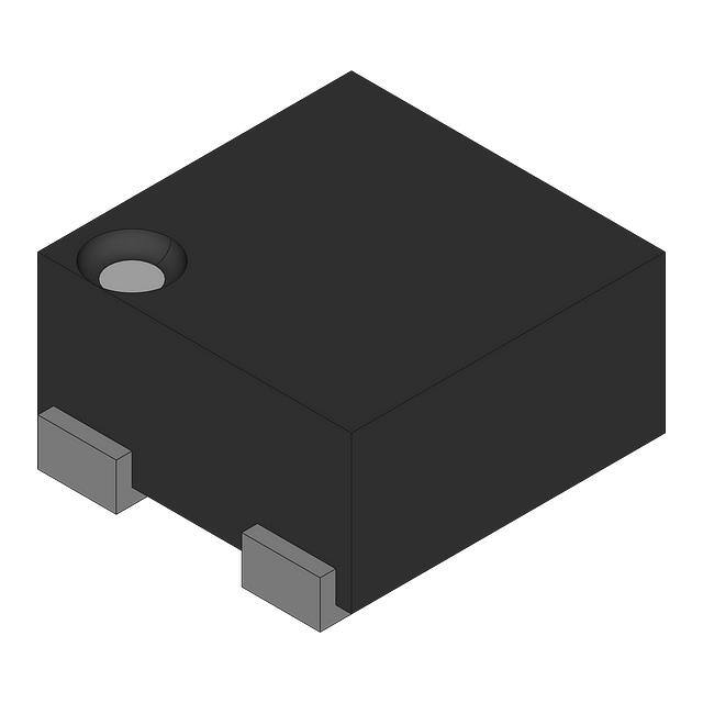
Three types of packages, SOT-23-5, SC-88A, and DFN(PLP)1010-4 are available.
FEATURES∗
• Supply Current ...................................................................... Typ. 0.29µA (VDD=6.0V)
Consumption current through SENSE pin is not included.
• Operating Voltage Range...................................................... 1.0V to 6.0V (-40°C <
= Topt <
= 105°C)
• Detector Threshold Range .................................................... 0.7V to 5.0V (0.1V steps)
(For other voltages, please refer to MARK INFORMATIONS.)
• Accuracy Detector Threshold................................................ ±1.0% (-VDET >
= 1.6V), ±15mV (-VDET>Ra. Refer to the electrical characteristics table to see the
RSENSE value.
VDD
Vs
VDD
Ra
-VDET
Rb
SENSE
R3117x
Series
GND
Fig.3
12
Vs
Ra
Ia
-VDET
DOUT
Rb
Ib
R3117x
Series
SENSE
ISENSE
RSENSE
GND
Fig.4
�R3117xxx3/4
Accuracy Detector Threshold
If the VDD bias voltage is lager than 5.25V, and to keep the detector threshold accuracy level, or if the maximum
operating voltage line must be used as the VDD bias voltage, the input voltage must be set low by using the divider
resistors which are shown in Fig.5.
VB
R1
Vs
Ra
-VDET
Rb
VDD
SENSE
R3117x
Series
R2
DOUT
GND
Fig.5
13
�R3117xxx3/4
Detector Operation vs. glitch input voltage to the SENSE pin
When the R3117x is at released, if the pulse voltage which the detector threshold or lower voltage, the graph
below means that the relation between pulse width and the amplitude of the swing to keep the released state for
the R3117x.
Pulse Width
Sense Voltage (VSENSE)
Detector Threshold (-VDET)
Over Drive
VSENSE Input Waveform
This graph shows the maximum pulse conditions to keep the released voltage. If the pulse with larger amplitude
or wider width than the graph above, is input to SENSE pin, the reset signal may be output.
14
�R3117xxx3/4
TEST CIRCUITS
ISS
VIN
SENSE
5V or VDD
VDD
VDD
R3117x
Series
VIN
SENSE
R3117x
Series
470kΩ
DOUT
VOUT
GND
GND
Supply Current Test Circuit
Detector Threshold Test Circuit
(Pull-up circuit is not necessary for
CMOS Output type.)
VDD
VIN
SENSE
R3117x
Series
IOUT
DOUT
GND
Nch Driver Output Current Test Circuit
VDS
VDD
VIN
VDS
SENSE
R3117x
Series
IOUT
DOUT
VDD−VDS
GND
Pch Driver Output Current Test Circuit
∗Apply to CMOS Output type only
15
�R3117xxx3/4
TYPICAL CHARACTERISTICS
1) Supply Current vs. Supply Voltage
R3117xxxxA/C (at released)
R3117xxxxA/C (at detect)
2) Detector Threshold vs. Temperature
R3117x07xA/C
R3117x50xA/C
16
R3117x30xA/C
�R3117xxx3/4
3) Detector Threshold vs. Supply Voltage
R3117x07xA/C
R3117x30xA/C
R3117x50xA/C
4) Hysteresis vs. Supply Voltage
R3117x07xA/C
R3117x30xA/C
17
�R3117xxx3/4
R3117x50xA/C
5) Output Voltage vs. SENSE pin Input Voltage (Nch Open Drain Output type is pulled up to VDD.)
R3117x07xA/C
R3117x50xA/C
18
R3117x30xA/C
�R3117xxx3/4
6) Nch Driver Output Current vs. Supply Voltage
R3117xxxxA/C
8) Pch Driver Output Current vs. Supply Voltage
R3117xxxxC
7) Nch Driver Output Current vs. VDS
R3117xxxxA/C
9) Pch Driver Output Current vs. VDS
R3117xxxxC
19
�R3117xxx3/4
TYPICAL APPLICATION
•
R3117xxxxA CPU Reset Circuit (Nch Open Drain Output)
(1) Input Voltage to R3117xxxxA is equal to Input Voltage to CPU
VDD
470kΩ R
VDD
VDD
Vs
CPU
R3117xxxxA
Series
DOUT
SENSE
RESET
GND
GND
(2) Input Voltage to R3117xxxxA is unequal to Input Voltage to CPU
VDD1
470kΩ R
VDD
Vs
R3117xxxxA
Series
DOUT
SENSE
GND
•
VDD2
VDD
CPU
RESET
GND
R3117xxxxC CPU Reset Circuit (CMOS Output)
VDD
VDD
Vs
R3117xxxxC
Series
DOUT
SENSE
GND
20
VDD
CPU
RESET
GND
�R3117xxx3/4
TECHNICAL NOTES
When connecting resistors to the device’s input pin
When connecting a resistor (R1) to an input of this device, the input voltage decreases by [Device’s
Consumption Current] x [Resistance Value] only. And, the cross conduction current*1, which occurs when
changing from the detecting state to the release state, is decreased the input voltage by [Cross Conduction
Current] x [Resistance Value] only. And then, this device will enter the re-detecting state if the input voltage
reduction is larger than the difference between the detector voltage and the released voltage.
When the input resistance value is large and the VDD is gone up at mildly in the vicinity of the released voltage,
repeating the above operation may result in the occurrence of output.
As shown in Figure A/B, set R1 to become 100 kΩ or less as a guide, and connect CIN of 0.1 μF and more to
between the input pin and GND. Besides, make evaluations including temperature properties under the actual
usage condition, with using the evaluation board like this way. As a result, make sure that the cross conduction
current has no problem.
R1
R1
VDD
CIN
*2
Voltage
Detector
VDD
OUT pin
R2
CIN
*2
GND
Figure A
Voltage
Detector
OUT pin
GND
Figure B
*1 In the CMOS output type, a charging current for OUT pin is included.
*2 Note the bias dependence of capacitors.
21
�1. The products and the product specifications described in this document are subject to change or discontinuation of
production without notice for reasons such as improvement. Therefore, before deciding to use the products, please
refer to Ricoh sales representatives for the latest information thereon.
2. The materials in this document may not be copied or otherwise reproduced in whole or in part without prior written
consent of Ricoh.
3. Please be sure to take any necessary formalities under relevant laws or regulations before exporting or otherwise
taking out of your country the products or the technical information described herein.
4. The technical information described in this document shows typical characteristics of and example application circuits
for the products. The release of such information is not to be construed as a warranty of or a grant of license under
Ricoh's or any third party's intellectual property rights or any other rights.
5. The products listed in this document are intended and designed for use as general electronic components in standard
applications (office equipment, telecommunication equipment, measuring instruments, consumer electronic products,
amusement equipment etc.). Those customers intending to use a product in an application requiring extreme quality
and reliability, for example, in a highly specific application where the failure or misoperation of the product could result
in human injury or death (aircraft, spacevehicle, nuclear reactor control system, traffic control system, automotive and
transportation equipment, combustion equipment, safety devices, life support system etc.) should first contact us.
6. We are making our continuous effort to improve the quality and reliability of our products, but semiconductor products
are likely to fail with certain probability. In order to prevent any injury to persons or damages to property resulting from
such failure, customers should be careful enough to incorporate safety measures in their design, such as redundancy
feature, fire containment feature and fail-safe feature. We do not assume any liability or responsibility for any loss or
damage arising from misuse or inappropriate use of the products.
7. Anti-radiation design is not implemented in the products described in this document.
8. The X-ray exposure can influence functions and characteristics of the products. Confirm the product functions and
characteristics in the evaluation stage.
9. WLCSP products should be used in light shielded environments. The light exposure can influence functions and
characteristics of the products under operation or storage.
10. There can be variation in the marking when different AOI (Automated Optical Inspection) equipment is used. In the
case of recognizing the marking characteristic with AOI, please contact Ricoh sales or our distributor before attempting
to use AOI.
11. Please contact Ricoh sales representatives should you have any questions or comments concerning the products or
the technical information.
Halogen Free
Ricoh is committed to reducing the environmental loading materials in electrical devices
with a view to contributing to the protection of human health and the environment.
Ricoh has been providing RoHS compliant products since April 1, 2006 and Halogen-free products since
April 1, 2012.
https://www.e-devices.ricoh.co.jp/en/
Sales & Support Offices
Ricoh Electronic Devices Co., Ltd.
Shin-Yokohama Office (International Sales)
2-3, Shin-Yokohama 3-chome, Kohoku-ku, Yokohama-shi, Kanagawa, 222-8530, Japan
Phone: +81-50-3814-7687 Fax: +81-45-474-0074
Ricoh Americas Holdings, Inc.
675 Campbell Technology Parkway, Suite 200 Campbell, CA 95008, U.S.A.
Phone: +1-408-610-3105
Ricoh Europe (Netherlands) B.V.
Semiconductor Support Centre
Prof. W.H. Keesomlaan 1, 1183 DJ Amstelveen, The Netherlands
Phone: +31-20-5474-309
Ricoh International B.V. - German Branch
Semiconductor Sales and Support Centre
Oberrather Strasse 6, 40472 Düsseldorf, Germany
Phone: +49-211-6546-0
Ricoh Electronic Devices Korea Co., Ltd.
3F, Haesung Bldg, 504, Teheran-ro, Gangnam-gu, Seoul, 135-725, Korea
Phone: +82-2-2135-5700 Fax: +82-2-2051-5713
Ricoh Electronic Devices Shanghai Co., Ltd.
Room 403, No.2 Building, No.690 Bibo Road, Pu Dong New District, Shanghai 201203,
People's Republic of China
Phone: +86-21-5027-3200 Fax: +86-21-5027-3299
Ricoh Electronic Devices Shanghai Co., Ltd.
Shenzhen Branch
1205, Block D(Jinlong Building), Kingkey 100, Hongbao Road, Luohu District,
Shenzhen, China
Phone: +86-755-8348-7600 Ext 225
Ricoh Electronic Devices Co., Ltd.
Taipei office
Room 109, 10F-1, No.51, Hengyang Rd., Taipei City, Taiwan (R.O.C.)
Phone: +886-2-2313-1621/1622 Fax: +886-2-2313-1623
�


 工商网监
湘ICP备2023018690号
工商网监
湘ICP备2023018690号
