R5117x Series
AEC-Q100 Compliant
42 V Input Power Management IC with Battery Voltage Detector
for Automotive Applications
No.EC-501-210219
OVERVIEW
The R5117x is a Power Management IC designed for automotive applications, featuring input voltage range
from 3.5V to 42V. This IC includes Battery Voltage Detector, SENSE Voltage Detector and 500 mA Voltage
Regulator in a single chip.
KEY BENEFITS
Reducing components and improving functional safety
The Battery Voltage Detector suitable for Early Warning System against battery voltage reduction
Preventing the false detection of transient characteristic fluctuations by high-speed response Voltage
Regulator
KEY SPECIFICATIONS
TYPICAL APPLICATIONS
Input Voltage Range (Max. rating):
3.5 V to 42.0 V (50.0 V)
Supply Current: Typ. 35 µA
Voltage Regulator (VR)
Output Voltage Range: 3.3 V to 5.0 V
Output Voltage Accuracy:
-1.25% to 0.75%(−40°C ≤Ta≤ 125°C)
Output Current: 500 mA
Protection:
Thermal shutdown (Detection Temp. Typ.175 °C)
Output current (Typ.750 mA)
Output short-circuit (Typ.105 mA)
SENSE Voltage Detector (SVD)
Detector Threshold : 2.5 V to 5.0 V (in 0.01V step)
Detector Threshold Accuracy :
-1.25% to 0.75%(−40°C ≤Ta≤ 125°C)
Release hysteresis: max 0.7%
Battery Voltage Detector (BVD)
Detector Threshold : 3.5 V to 12.0 V (in 0.1V step)
Detector Threshold Accuracy :
-2.0% to 1.0% (−40°C ≤Ta≤ 125°C)
Release hysteresis: max 5.0%
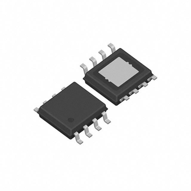
PACKAGES
VIN
Microprocessor
VDD
VOUT
VCC
R5117x
CIN
R1
R2
CD
SENSE
CE
BVD
I/O
GND
SVD
RESET
CD
COUT
•
•
CIN: 1.0µF, COUT: 10µF, Ceramic capacitors
CD: Ceramic capacitors for setting detection
delay time
SELECTION GUIDE
Product Name
Package
Quantity
per Reel
R5117SxxxA-E2-#E
HSOP-8E
1,000 pcs
R5117LxxxA-TR-#E
HQFN0808-28
2,000 pcs
xxx:
Specify the set output voltage for VR (VVRSET),
the set Battery voltage detector threshold (VBVSET)
and the set SENSE voltage detector threshold
(VSVSET) by using serial numbers starting from 001
Refer to ELECTRICAL CHARACTERISTICS for detail
information.
HSOP-8E
5.2 x 6.2 x 1.45 (mm)
HQFN0808-28
8.8 x 8.8 x 0.95 (mm)
APPLICATIONS
•
•
Power supply system with microprocessor devices for In-Vehicle electrical equipment
Power supply system for electronic control units such as EV inverter and battery charge control unit
1
�R5117x
No.EC-501-210219
SELECTION GUIDE
The set output voltages and the quality class are user-selectable options.
Product Name
Package
Quantity per Reel
Pb Free
Halogen Free
R5117SxxxA-E2-#E
HSOP-8E
1,000 pcs
Yes
Yes
R5117LxxxA-TR-#E
HQFN0808-28
2,000 pcs
Yes
Yes
xxx: Specify the set output voltage for Voltage Regulator (VVRSET),
the set Battery voltage detector threshold (VBVSET) and the set SENSE voltage detector threshold
(VSVSET) by using serial numbers starting from 001(1)
Refer to ELECTRICAL CHARACTERISTICS for detail information
#: Select the quality class
Operating Temperature Range
Test Temperature
A
−40°C to 125°C
25°C, High
K
−40°C to 125°C
Low, 25°C, High
(1) The
combinations of VVRSET, VBVSET, VSVSET are following conditions;
・VVRSET = 3.3 V to 5.0 V
・VBVSET = 3.5 V to 12.0 V
・VSVSET = 2.5 V to 5.0 V
2
�R5117x
No.EC-501-210219
BLOCK DIAGRAM
VDD
Thermal shutdown
VOUT
ON/OFF
Circuit
CD
CE
Current Limit
SENSE
Logic
BVD
SVD
Delay
Circuit
GND
R5117xxx Block Diagram
3
�R5117x
No.EC-501-210219
PIN DESCRIPTION
8
Top View
7
6
5
Bottom View
5
6
7
8
2
1
(1)
1
2
3
4
4
3
1
R5117S (HSOP-8E) Pin Configuration
R5117S (HSOP-8E)
Pin No.
Symbol
Description
1
VDD
2
CD
Pin for setting VD Release Output Delay Time (power-on reset time)
3
CE
Chip Enable Pin (Active-high)
4
GND
Ground Pin
5
SVD
SENSE Voltage Reduction Detection Output Pin (“Low” at detection)
6
BVD
Battery Voltage Reduction Detection Output Pin (“Low” at detection)
7
SENSE
8
VOUT
Supply Voltage Pin
SENSE Input Voltage Pin
Regulator Output Pin
(1) The
tab on the bottom of the package is substrate level (GND). It is recommended that the tab be connected to the
ground plane on the board.
4
�R5117x
No.EC-501-210219
Top View
Bottom View
(1)
1
R5117L(HQFN0808-28) Pin Configuration
R5117L(HQFN0808-28)
Pin No.
1
2
3
4
5
6
7
8
9
10
11
12
13
14
15
16
17
18
19
20
21
22
23
24
25
26
27
28
Symbol
Tab (GND)
NC
VDD
VDD
NC
CD
Tab (GND)
Tab (GND)
CE
NC
GND
GND
NC
Tab (GND)
Tab (GND)
SVD
BVD
NC
SENSE
VOUT
Tab (GND)
Tab (GND)
NC
NC
NC
NC
NC
Tab (GND)
Description
Tab
※Internally shorted to the GND
No Connection
Power Supply Pin
※Internally shorted to the 4Pin
Power Supply Pin
※Internally shorted to the 3Pin
No Connection
Voltage Detector Reset Delay Time (Power-on Reset Time) Setting Pin
Tab
※Internally shorted to the GND
Tab
※Internally shorted to the GND
Chip Enable Pin, Active-high
No Connection
Ground Pin
※Internally shorted to the 12Pin
Ground Pin
※Internally shorted to the 11Pin
No Connection
Tab
※Internally shorted to the GND
Tab
※Internally shorted to the GND
SENSE Voltage Reduction Detection Output Pin (“Low” at detection)
Battery Voltage Reduction Detection Output Pin (“Low” at detection)
No Connection
SENSE Pin
Voltage Regulator Output Pin
Tab
※Internally shorted to the GND
Tab
※Internally shorted to the GND
No Connection
No Connection
No Connection
No Connection
No Connection
Tab
※Internally shorted to the GND
(1) The
tab on the bottom of the package is substrate level (GND). It is recommended that the tab be connected to the
ground plane on the board.
5
�R5117x
No.EC-501-210219
PIN EQUIVALENT CIRCUIT DIAGRAMS
< VOUT Pin >
< CE Pin >
Driver
CE
VOUT
< CD Pin >
< BVD Pin >
OV
Driver
CD
Driver
< SVD Pin >
< SENSE Pin >
SENSE
UV
Driver
6
�R5117x
No.EC-501-210219
ABSOLUTE MAXIMUM RATINGS
Symbol
Parameter
Rating
Unit
−0.3 to 50
V
Peak Input Voltage (1)
60
V
VCE
CE Pin Input Voltage
−0.3 to 50
V
VOUT
Output Voltage
−0.3 to VIN + 0.3 ≤ 50
V
SENSE Pin Voltage
−0.3 to 50
V
VCD
CD Pin Output Voltage
−0.3 to 50
V
VBVD
BVD Pin Output Voltage
−0.3 to 7.0
V
VSVD
SVD Pin Output Voltage
−0.3 to 7.0
V
Input Voltage
VIN
VSENSE
PD
Power Dissipation
Refer to Appendix “Power Dissipation”
Tj
Junction Temperature
−40 to 150
°C
Tstg
Storage Temperature
−55 to 150
°C
ABSOLUTE MAXIMUM RATINGS
Electronic and mechanical stress momentarily exceeded absolute maximum ratings may cause permanent damage
and may degrade the lifetime and safety for both device and system using the device in the field. The functional
operation at or over these absolute maximum ratings are not assured.
RECOMMENDED OPERATING CONDITIONS
Symbol
Parameter
Rating
Unit
3.5 to 42
V
VIN
Input Voltage
VCE
CE Pin Input Voltage
0 to 42
V
VSENSE
SENSE Pin Input Voltage
0 to 6.0
V
VBVD
BVD Pin Output Voltage
0 to 6.0
V
VSVD
SVD Pin Output Voltage
0 to 6.0
V
Ta
Operating Temperature
−40 to 125
°C
RECOMMENDED OPERATING CONDITIONS
All of electronic equipment should be designed that the mounted semiconductor devices operate within the
recommended operating conditions. The semiconductor devices cannot operate normally over the recommended
operating conditions, even if they are used over such conditions by momentary electronic noise or surge. And the
semiconductor devices may receive serious damage when they continue to operate over the recommended
operating conditions.
(1) Duration
time: 200 ms
7
�R5117x
No.EC-501-210219
ELECTRICAL CHARACTERISTICS
CIN = 1.0 µF, COUT = 10 µF, VIN = 14 V, unless otherwise noted.
The specifications surrounded by
are guaranteed by design engineering at −40°C ≤ Ta ≤ 125°C.
R5117xxxx-AE
For All
(Ta = 25°C)
Symbol
ISS
Parameter
Supply Current
Istandby Standby Current
Condition
Min.
3.5V ≤ VBVSET < 8.0V
IOUT = 0 mA (1)
Typ.
35
8.0V ≤ VBVSET ≤ 12.0V
VIN = 14 V, VCE = 0 V (1)
Max.
65
Unit
µA
60
10
25
µA
0.2
0.6
µA
IPD
CE Pull-down Current
VCEH
CE Input Voltage, high
2.0
42
V
VCEL
CE Input Voltage, low
0
1.0
V
All test items listed under Electrical Characteristics are done under the pulse load condition (Tj ≈ Ta = 25°C).
VR Section
Symbol
VOUT
(Ta = 25°C)
Parameter
Output Voltage
∆VOUT/
Load Regulation
∆IOUT
VDIF
Dropout Voltage
∆VOUT/
Line Regulation
∆VIN
Condition
VIN = 14 V,
IOUT = 1 mA
VIN = VSET + 3.0 V
IOUT = 500 mA
IOUT = 1 mA
Min.
Typ.
Max.
Ta = 25°C
×0.995
×1.005
−40°C ≤ Ta ≤ 125°C
×0.9875
×1.0075
1 mA ≤ IOUT ≤ 300 mA
−10
1 mA ≤ IOUT ≤ 500 mA
−15
0
10
15
VSET = 3.3 V
1.1
1.7
VSET = 5.0 V
0.9
1.5
8.0 V ≤ VIN ≤ 16 V
−10
6.0 V ≤ VIN ≤ 32 V
-25
0
10
25
Unit
V
mV
V
mV
ILIM
Output Current Limit
VIN = 8.0 V
500
750
ISC
Short Current Limit
VOUT = 0 V
70
105
Junction Temperature
165
175
°C
Junction Temperature
125
145
°C
TTSD
TTSR
Thermal Shutdown
Temperature
Thermal Shutdown
Release Temperature
mA
150
mA
All test items listed under Electrical Characteristics are done under the pulse load condition (Tj ≈ Ta = 25°C).
(1) Supply
current, Standby current are depending on VDD Voltage and battery voltage detector setting when the detector
power is turned on all the time. Refer to the Supply Current data in TYPICAL CHARACTERISTICS for detail information.
8
�R5117x
No.EC-501-210219
ELECTRICAL CHARACTERISTICS
CIN = 1.0 µF, COUT = 10 µF, VIN = 14 V, unless otherwise noted.
The specifications surrounded by
are guaranteed by design engineering at −40°C ≤ Ta ≤ 125°C.
SVD / BVD Sections
Symbol
Parameter
(Ta = 25°C)
Condition
Ta = 25°C
Min.
Typ.
Max.
×0.992
×1.008
−40°C ≤ Ta ≤ 125°C
×0.98
×1.01
Ta = 25°C
×0.995
×1.005
−40°C ≤ Ta ≤ 125°C
×0.9875
×1.0075
Unit
VBVDET
Battery Voltage Detector
Threshold
VSVDET
SENSE Voltage Detector
Threshold
VBVHYS
Battery Voltage
Threshold Hysteresis
VBVDET
×0.01
VBVDET
×0.05
V
SENSE Voltage Detector
Threshold Hysteresis
Release Output Delay
Time (Power-on Reset)
UVLO Detector
Threshold
UVLO Detector
Threshold Hysteresis
VSVDET VSVDET VSVDET
×0.003 ×0.005 ×0.007
V
VSVHYS
tDELAY
VUVLO
VUVLOHYS
CD = 10 nF (1)
2
VBVDET
×0.03
V
V
4
8
ms
1.8
2.8
V
0.1
0.2
V
VBVD
BVD Pull-up Voltage
6.0
V
VSVD
SVD Pull-up Voltage
6.0
V
IOUTBVD
IOUTSVD
ILEAKBVD
ILEAKSVD
RLCD
Nch Output Current
(BVD Output Pin)
Nch Output Current
(SVD Output Pin)
Nch Leakage Current
(BVD Output Pin)
Nch Leakage Current
(SVD Output Pin)
CD Pin Discharge
Nch Tr.ON Resistance
VIN = VBVDET – 0.1V, VDS = 0.1 V
0.8
2.0
mA
VIN = 3.0 V, VDS = 0.1 V
0.8
2.0
mA
VBVD = 5.5 V
0.3
µA
VSVD = 5.5 V
0.3
µA
3.0
kΩ
VCE = 0 V, VCD = 0.1 V
1.2
All test items listed under Electrical Characteristics are done under the pulse load condition (Tj ≈ Ta = 25°C).
(1) t
DELAY is adjustable by only CD of SENSE Voltage Detector. tDELAY of Battery Voltage Detector is fixed internally. Refer to
Release delay time data in TYPICAL CHARACTERISTICS for detail information.
9
�R5117x
No.EC-501-210219
ELECTRICAL CHARACTERISTICS
CIN = 1.0 µF, COUT = 10 µF, VIN = 14 V, unless otherwise noted.
R5117xxxx-KE
For All
(−40°C ≤ Ta ≤ 125°C)
Symbol
ISS
Parameter
Condition
Supply Current
IOUT = 0 mA (1)
Istandby Standby Current
Min.
3.5V ≤ VBVDET < 8.0V
Typ.
35
8.0V ≤ VBVDET ≤ 12.0V
VIN = 14 V, VCE = 0 V (1)
Max.
65
60
Unit
µA
10
25
µA
0.2
0.6
µA
IPD
CE Pull-down Current
VCEH
CE Input Voltage, high
2.0
42
V
VCEL
CE Input Voltage, low
0
1.0
V
VR Section
Symbol
VOUT
(−40°C ≤ Ta ≤ 125°C)
Parameter
Output Voltage
∆VOUT/
Load Regulation
∆IOUT
VDIF
Dropout Voltage
∆VOUT/
Line Regulation
∆VIN
Condition
VIN =14 V,
IOUT = 1 mA
VIN = VSET + 3.0 V
IOUT = 500 mA
IOUT = 1 mA
Min.
Typ.
Max.
Ta = 25°C
×0.995
×1.005
−40°C ≤ Ta ≤ 125°C
×0.9875
×1.0075
1 mA ≤ IOUT ≤ 300 mA
−10
1 mA ≤ IOUT ≤ 500 mA
−15
0
10
15
VSET = 3.3 V
1.1
1.7
VSET = 5.0 V
0.9
1.5
8.0 V ≤ VIN ≤ 16 V
−10
6.0 V ≤ VIN ≤ 32 V
-25
0
10
25
Unit
V
mV
V
mV
ILIM
Output Current Limit
VIN = 8.0 V
500
750
mA
ISC
Short Current Limit
VOUT = 0 V
70
105
TTSD
Thermal Shutdown
Temperature
Junction Temperature
165
175
°C
TTSR
Thermal Shutdown
Junction Temperature
Release Temperature
125
145
°C
150
mA
(1) Supply
current, Standby current are depending on VDD Voltage and battery voltage detector setting when the detector
power is turned on all the time. Refer to the Supply Current data in TYPICAL CHARACTERISTICS for detail information.
10
�R5117x
No.EC-501-210219
ELECTRICAL CHARACTERISTICS
CIN = 1.0 µF, COUT = 10 µF, VIN = 14 V, unless otherwise noted.
SVD / BVD Sections
Symbol
Parameter
(−40°C ≤ Ta ≤ 125°C)
Min.
Typ.
Max.
Condition
Ta = 25°C
×0.992
×1.008
−40°C ≤ Ta ≤ 125°C
×0.98
×1.01
Ta = 25°C
×0.995
×1.005
−40°C ≤ Ta ≤ 125°C
×0.9875
×1.0075
Unit
VBVDET
Battery Voltage Detector
Threshold
VSVDET
SENSE Voltage Detector
Threshold
VBVHYS
Battery Voltage Detector
Threshold Hysteresis
VBVDET
×0.01
VBVDET
×0.05
V
SENSE Voltage Detector
Threshold Hysteresis
Release Output Delay
Time (Power-on Reset)
VSVDET VSVDET VSVDET
×0.003 ×0.005 ×0.007
V
VSVHYS
tDELAY
CD = 10 nF ( 1)
2
VBVDET
×0.03
V
V
4
8
ms
VUVLO
UVLO Detector Threshold
1.8
2.8
V
VUVLOHYS
UVLO Detector Threshold
Hysteresis
0.1
0.2
V
VBVD
BVD Pull-up Current
6.0
V
VSVD
SVD Pull-up Current
6.0
V
IOUTBVD
IOUTSVD
ILEAKBVD
ILEAKSVD
RLCD
Nch Output Current
(BVD Output Pin)
Nch Output Current
(SVD Output Pin)
Nch Leakage Current
(BVD Output Pin)
Nch Leakage Current
(SVD Output Pin)
CD Pin Discharge
Nch Tr.ON Resistance
VIN = VBVDET – 0.1V,
VDS = 0.1 V
0.8
2.0
mA
VIN = 3.0 V, VDS = 0.1 V
0.8
2.0
mA
VBVD = 5.5 V
0.3
µA
VSVD = 5.5 V
0.3
µA
3.0
kΩ
VCE = 0 V, VCD = 0.1 V
1.2
(1) t
DELAY is adjustable by only CD of SENSE Voltage Detector. tDELAY of Battery Voltage Detector is fixed internally. Refer to
Release delay time data in TYPICAL CHARACTERISTICS for detail information.
11
�R5117x
No.EC-501-210219
R5117x (-AE) Product-specific Electrical Characteristics
The specifications surrounded by
are guaranteed by design engineering at −40°C ≤ Ta ≤ 125°C
VOUT
Ta=25°C
Min.
Typ.
Max.
VOUT
-40°C ≤ Ta ≤ 125°C
Min.
Typ.
Max.
R5117x001A
4.975
5.000
5.025
4.938
5.000
5.037
R5117x002A
3.284
3.300
3.316
3.259
3.300
3.324
VBVDET
Ta=25°C
Min.
Typ.
Max.
VBVDET
-40°C ≤ Ta ≤ 125°C
Min.
Typ.
Max.
R5117x001A
6.647
6.700
6.753
6.566
6.700
R5117x002A
5.159
5.200
5.241
5.096
5.200
Min.
VSVDET
Ta=25°C
Typ.
Max.
VSVDET
-40°C ≤ Ta ≤ 125°C
Min.
Typ.
Max.
R5117x001A
4.796
4.820
4.844
4.760
4.820
R5117x002A
3.165
3.180
3.195
3.141
3.180
Product Name
Product Name
Product Name
Min.
VBVHYS
Ta=25°C
Typ.
Max.
6.767
0.06700
0.20100
0.33500
5.252
0.05200
0.15600
0.26000
Min.
VSVHYS
Ta=25°C
Typ.
Max.
4.856
0.01446
0.02410
0.03374
3.203
0.00954
0.01590
0.02226
Min.
VBVHYS
Ta=25°C
Typ.
Max.
R5117x (-KE) Product-specific Electrical Characteristics
VOUT
Ta=25°C
Min.
Typ.
Max.
VOUT
-40°C ≤ Ta ≤ 125°C
Min.
Typ.
Max.
R5117x001A
4.975
5.000
5.025
4.938
5.000
5.037
R5117x002A
3.284
3.300
3.316
3.259
3.300
3.324
VBVDET
Ta=25°C
Min.
Typ.
Max.
VBVDET
-40°C ≤ Ta ≤ 125°C
Min.
Typ.
Max.
R5117x001A
6.647
6.700
6.753
6.566
6.700
6.767
0.06700
0.20100
0.33500
R5117x002A
5.159
5.200
5.241
5.096
5.200
5.252
0.05200
0.15600
0.26000
Min.
VSVDET
Ta=25°C
Typ.
Max.
VSVDET
-40°C ≤ Ta ≤ 125°C
Min.
Typ.
Max.
Min.
VSVHYS
Ta=25°C
Typ.
Max.
R5117x001A
4.796
4.820
4.844
4.760
4.820
4.856
0.01446
0.02410
0.03374
R5117x002A
3.165
3.180
3.195
3.141
3.180
3.203
0.00954
0.01590
0.02226
Product Name
Product Name
Product Name
12
�R5117x
No.EC-501-210219
THEORY OF OPERATION
Thermal Shutdown
When the junction temperature of this device exceeds 175°C (Typ.), the built-in thermal shutdown circuit stops
the regulator operation. After that, when the temperature drops to 145°C (Typ.) or lower, the regulator restarts
the operation. Unless eliminating the overheating problem, the regulator turns on and off repeatedly and a
pulse shaped output voltage occurs as result.
R5117xxx Voltage Detector
VIN
VBVDET
VBVREL
VUVLO
VUVLO+VUVLOHYS
VSENSE
VSVREL
VSVREL
VSVDET
BVD
(4)
(1)
tDELAY
tDELAY
SVD
(2)
(3)
(5)
UVLO Release Voltage: VUVLO+VUVLOHYS
UVLO Detector Threshold: VUVLO
Battery Voltage Release Voltage: VBVREL
Battery Voltage Detector Threshold: VBVDET
SENSE Voltage Release Voltage: VSVREL
SENSE Voltage Detecor Threshold: VSVDET
R5117xxx Voltage Detector Timing Chart
(1) When the Input pin voltage (VIN) exceed the Battery voltage release voltage (VBVREL), the BVD pin output
becomes “High” after the release delay time (Typ. 20µs).
(2) When SENSE pin voltage (VSENSE) exceed the SENSE voltage release voltage (VSVREL), the SVD pin
output becomes “High” after the release delay time (tDELAY).
(3) When VSENSE decreases less than the SENSE voltage detector threshold (VSVDET), the SVD pin output
becomes “Low” after the detection delay time (Typ.100 µs) and enters the SENSE voltage detecting state.
(4) When the Input pin voltage (VIN) decreases less than the Battery voltage detector threshold (VBVDET), the
BVD pin output becomes “Low” after the detection delay time (Typ.6.0µs) and enters the Battery voltage
detecting state.
(5) When the Input pin voltage (VIN) decreases less than the UVLO detector threshold (VUVLO), the SVD pin
output becomes “Low”.
13
�R5117x
No.EC-501-210219
SENSE Voltage Monitoring VD Delay Operation and Release Delay Time (tDELAY)
At SENSE Voltage Detection
When supplying a voltage higher than the SENSE voltage release voltage (VSVREL) to the SENSE pin, a
charging to an external capacitor starts and the CD pin voltage (VCD) increases. The SVD pin voltage (VSVD)
maintains “Low” until VCD reaches the CD pin threshold voltage (VTCD). When VCD exceeds VTCD, VSVD is inverted
from “Low” to “High”. The release delay time (tDELAY) is the period from the time the SENSE pin voltage (VSENSE)
exceeds VSVREL to a rising edge of VSVD. When the output voltage turns from “Low” to “High”, a charge carrier
of the external capacitor starts discharging. When supplying a voltage lower than the SENSE voltage detector
threshold (VSVDET) to the SENSE pin, the detection delay time (tPHL) remains constant independently of the
external capacitor. tPHL is the period that VSVD is inverted from “High” to “Low”.
VSVREL
VSVDET
SENSE Pin
VTCD
CD Pin Voltage
GND
UV Pin
GND
Release Delay Time
(tDELAY)
Detection Delay Time
(tPHL)
SENSE Voltage Release Delay Timing Diagram
Calculation of SENSE Voltage Release Delay Time
The following equation can calculate a typical value of the release delay time (tDELAY) with using the external
capacitor (CD).
tDELAY (s) = 0.72 × CD (F) / (1.8×10⁻⁶)
tDELAY is the period from supplying a pulse voltage of “1.0 V to (VSVDET) + 1.0 V” to the SENSE pin by pulling-up
SVD pin to 5 V with 100 kΩ resistor to the SVD pins reached 2.5 V.
VUVDET + 1.0 V
SENSE Pin
1.0 V
GND
5.0 V
SVD Pin
2.5 V
GND
tPHL
tDELAY
14
�R5117x
No.EC-501-210219
Voltage Setting of Voltage Regulator
The SENSE Voltage Detector (SVD) detects the drop and rise of the Voltage Regulator (VR). When the SENSE
release voltage is set to a voltage above the VR output voltage, the reset signal of SVD is not released even if
SVD monitors the VR output voltage returns to the normal value after detecting the drop of VR.
To prevent this issue, the following conditions are required between VOUT and VSVREL.
(VR Set Output Voltage) x 0.9875 − 15 mV* > (SENSE Set Detector Threshold) x 1.0075 x 1.007
* 15mV is the worst value of load regulation
When using a device without the above conditions of VOUT and VSVDET, careful consideration must be given to
the system operation before use.
15
�R5117x
No.EC-501-210219
APPLICATION INFORMATION
TYPICAL APPLICATIONS
VIN
Microprocessor
VDD
VOUT
VCC
R5117x
CIN
R1
R2
CD
SENSE
CE
BVD
I/O
GND
SVD
RESET
CD
COUT
R5117xxx TYPICAL APPLICATIONS
Recommended Components
Symbol
Description
CIN
Ceramic Capacitor, 1.0 μF or more, 50V Rated Voltage, CGA4J2X7R1H104K, TDK
COUT
Ceramic Capacitor, 10 μF or more, 50V Rated Voltage, CGA4J1X7R0J106K, TDK
CD
R1/R2
A capacitor corresponding to setting of Release Output Delay Time
A resistor covering the output current at Nch. driver ON and the leakage current at Nch.
driver OFF. Refer to “Electrical Characteristic” providing the evaluation result with using a
resistor of 100kΩ.
16
�R5117x
No.EC-501-210219
TYPICAL APPLICATION FOR IC CHIP BREAKDOWN PREVENTION
VIN
Microprocessor
VDD
VOUT
VCC
R5117x
CIN
CD
SENSE
CE
BVD
GND
SVD
I/O
D1
CD
RESET
COUT
R5117xxx Typical Application for IC Chip Breakdown Prevention
When a sudden surge of electrical current travels along the VOUT pin and GND due to a short-circuit,
electrical resonance of a circuit involving an output capacitor (COUT) and a short circuit inductor generates a
negative voltage and may damage the device or the load devices. Connecting a schottky diode (D1) between
the VOUT pin and GND has the effect of preventing damage to them.
17
�R5117x
No.EC-501-210219
TECHNICAL NOTES
The performance of a power source circuit using this device is highly dependent on a peripheral circuit. A
peripheral component or the device mounted on PCB should not exceed a rated voltage, a rated current or a
rated power. When designing a peripheral circuit, please be fully aware of the following points.
Phase Compensation
Phase compensation is provided to secure stable operation even when the load current is varied by utilizing
capacity of the output ceramic capacitor and Equivalent Series Resistance (ESR). For this purpose, be sure to
use a capacitor with 10 μF or more (COUT) and wire it to the pin as short as possible.
Evaluate the circuit with consideration of temperature and frequency characteristics, in case ESR value of the
capacitor is large and the output is unstable. The capacitor with 1.0 μF or more (CIN) connected in between
VDD pin and GND pin must be wired the shortest.
18
�R5117x
No.EC-501-210219
TYPICAL CHARACTERISTICS
49
42
42
35
Supply Current [μA]
Supply Current [μA]
Note: Typical Characteristics are intended to be used as reference data; they are not guaranteed.
1) Supply Current vs. Temperature (VIN = 14V)
VVRSET = 3.3V, VSVSET = 3.0V, VBVSET = 3.5V
VVRSET = 5.0V, VSVSET = 4.6V, VBVSET = 6.0V
35
28
21
14
21
14
7
7
0
28
0
-50
-25
0
25
50
75
100
125
-50
-25
0
84
72
72
60
48
36
24
-40[degC]
25[degC]
105[degC]
125[degC]
12
0
0
6
12
18
24
30
36
24
-40[degC]
25[degC]
105[degC]
125[degC]
0
6
18
12
24
30
36
42
Input Voltage [V]
Ta=-40[degC]
Ta=25[degC]
Ta=105[degC]
Ta=125[degC]
VVRSET = 5.0V, VSVSET = 4.6V, VBVSET = 6.0V
44
42
Supply Current [μA]
Supply Current [μA]
125
36
0
42
46
44
42
40
38
36
100
48
12
3) Supply Current vs. SENSE Voltage
VVRSET = 3.3V, VSVSET = 3.0V, VBVSET = 3.5V
48
75
60
Input Voltage [V]
50
50
VVRSET = 5.0V, VSVSET = 4.6V, VBVSET = 6.0V
84
Supply Current [μA]
Supply Current [μA]
2) Supply Current vs. Input Voltage
VVRSET = 3.3V, VSVSET = 3.0V, VBVSET = 3.5V
25
Temperature [degC]
Temperature [degC]
Ta=-40[degC]
Ta=25[degC]
Ta=105[degC]
Ta=125[degC]
40
38
36
34
32
0
1
2
3
4
SENSE Input Voltage [V]
5
6
30
0
1
2
3
4
5
6
SENSE Input Voltage [V]
19
�R5117x
No.EC-501-210219
3.5
6.0
3.0
5.0
2.5
Output Voltage [V]
Output Voltage [V]
4) Output Voltage vs. Output Current (VIN = VVRSET + 3.0 V, Ta =25 °C)
VVRSET = 3.3V
VVRSET = 5.0V
2.0
1.5
1.0
3.0
2.0
1.0
0.5
0.0
4.0
0
200
400
600
0.0
800
0
Output Current [mA]
3.0
4.8
2.5
4.0
Output Voltage [V]
Output Voltage [V]
5.6
2.0
1.5
0.0
1[mA]
50[mA]
2
4
6
8
10
12
3.2
2.4
1[mA]
1.6
50[mA]
0.8
100[mA]
0
800
600
VVRSET = 5.0V
3.5
0.5
400
Output Current [mA]
5) Output Voltage vs. Input Voltage (Ta =25 °C)
VVRSET = 3.3V
1.0
200
0.0
14
100[mA]
0
2
6
4
8
10
12
14
75
100
125
Input Voltage [V]
Input Voltage [V]
3.40
5.10
3.38
5.08
3.36
5.06
Output Voltage [V]
Output Voltage [V]
6) Output Voltage vs. Temperature (VIN = 14V, IOUT = 1 mA)
VVRSET = 3.3V
VVRSET = 5.0V
3.34
3.32
3.30
3.28
3.26
3.24
3.22
5.04
5.02
5.00
4.98
4.96
4.94
-50
-25
0
25
50
75
Temperature [degC]
100
125
4.92
-50
-25
0
25
50
Temperature [degC]
20
�R5117x
No.EC-501-210219
7) Output Voltage vs. Output Current
VVRSET = 3.3V
1750
1750
-40[degC]
25[degC]
105[degC]
125[degC]
1250
1000
750
500
250
0
-40[degC]
25[degC]
105[degC]
125[degC]
1500
Dropout Voltage [mV]
1500
Dropout Voltage [mV]
VVRSET = 5.0V
1250
1000
750
500
250
0
100
200
300
400
0
500
0
100
Output Current [mA]
200
300
500
400
Output Current [mA]
8) Ripple Rejection vs. Input Voltage (Ta=25 °C , Vripple = ± 0.2V)
VVRSET = 3.3V
VVRSET = 5.0V
140
140
100
1k[Hz]
10k[Hz]
100k[Hz]
120
Ripple Rejection [dB]
Ripple Rejection [dB]
120
100[Hz]
80
60
40
20
0
100[Hz]
1k[Hz]
10k[Hz]
100k[Hz]
100
80
60
40
20
0
6
12
18
24
30
36
0
42
0
6
12
Input Voltage [V]
18
24
30
36
42
Input Voltage [V]
120
120
100
100
Ripple Rejection [dB]
Ripple Rejection [dB]
9) Ripple Rejection vs. Frequency (Ta=25 °C , VIN = 14V ± 0.2Vripple)
VVRSET = 3.3V
VVRSET = 5.0V
80
60
40
1[mA]
50[mA]
100[mA]
20
0
0.1
1
10
Frequency [kHz]
100
1000
80
60
40
1[mA]
50[mA]
100[mA]
20
0
0.1
1
10
100
1000
Frequency [kHz]
21
�R5117x
No.EC-501-210219
15
10
10
0
Input Voltage
tr = tf = 1.0[μs]
3.35
3.30
Output Voltage
Input Voltage
tr = tf = 1.0[μs]
5
Input Voltage [V]
Input Voltage [V]
5
Output Voltage [V]
15
0
5.08
3.25
0.0 0.1 0.2 0.3 0.4 0.5 0.6 0.7 0.8 0.9
5.00
Output Voltage
3.20
4.92
0.0 0.1 0.2 0.3 0.4 0.5 0.6 0.7 0.8 0.9
Time [ms]
Output Voltage [V]
10) Input Transient Response (Ta=25 °C , VIN = VVRSET + 3.0 V ⇔ VVRSET + 8.0 V, IOUT = 1 mA)
VVRSET = 3.3V
VVRSET = 5.0V
4.84
Time [ms]
20
20
0
3.40
3.35
3.30
3.25
3.20
Output Voltage
Output Current
tr=tf=1.0[μs]
5.2
5.1
5.0
Output Voltage
4.9
4.8
0.0 0.1 0.2 0.3 0.4 0.5 0.6 0.7 0.8 0.9
0
Output Current [mA]
40
Output Voltage [V]
Output Current
tr=tf=1.0[μs]
40
Output Current [mA]
Output Voltage [V]
11) Load Transient Response (Ta=25 °C , IOUT = 1⇔20mA , VIN = 14V)
VVRSET = 3.3V
VVRSET = 5.0V
0.0 0.1 0.2 0.3 0.4 0.5 0.6 0.7 0.8 0.9
Time [ms]
Time [ms]
12) CE Transient Response (Ta=25 °C , VIN = 14V, IOUT = 1 mA)
VVRSET = 3.3V
VVRSET = 3.3V
Output Voltage
800
600
400
Inrush Current
0.0 0.2 0.4 0.6 0.8 1.0 1.2 1.4 1.6 1.8
time [ms]
200
0
CE Input Voltage
4
3
IOUT=1[mA]
2
IOUT=100[mA]
1
5
0
Input Voltage (V)
0
CE Input Voltage
Output Voltage [V]
Output Voltage [V]
5
Inrush Current [mA]
10
0
0
50 100 150 200 250 300 350 400 450
time [ms]
22
�R5117x
No.EC-501-210219
VVRSET = 5.0V
800
600
400
Inrush Current
200
0
6
IOUT=1[mA]
IOUT=100[mA]
2
0
0
time [ms]
VVRSET = 5.0V
60
50
50
40
40
30
Input Voltage
20
10
0
3.4
Output Voltage
3.3
Input Voltage [V]
60
Output Voltage [V]
Input Voltage [V]
50 100 150 200 250 300 350 400 450
time [ms]
13) Load Dump (Ta=25 °C , IOUT = 1 mA)
VVRSET = 3.3V
30
20
Input Voltage
10
0
5.15
Output Voltage
3.2
3.1
10 20 30 40 50 60 70 80 90
0
10 20 30 40 50 60 70 80 90
15
Input Voltage
10
5
0
4
Output Voltage
8
10 12 14 16 18
Time [μs]
3
Input Voltage [V]
15
Output Voltage [V]
Input Voltage [V]
20
6
4.55
VVRSET = 5.0V
20
4
4.85
Time [ms]
14) Cranking (Ta=25 °C , IOUT = 1 mA)
VVRSET = 3.3V
2
5.00
4.70
3.0
Time [ms]
0
0
4
0.0 0.2 0.4 0.6 0.8 1.0 1.2 1.4 1.6 1.8
0
5
CE Input Voltage
Output Voltage [V]
0
Output Voltage [V]
Output Voltage [V]
Output Voltage
Inrush Current [mA]
CE Input Voltage
5
Input Voltage
10
5
6
0
Output Voltage
4
3
2
1
5
Output Voltage [V]
10
Input Voltage (V)
VVRSET = 5.0V
2
0
2
4
6
8
10 12 14 16 18
1
Time [μs]
23
�R5117x
No.EC-501-210219
VSVSET = 4.6V, VBVSET = 6.0V
3.6
7.0
3.5
6.5
3.4
6.0
3.3
SVD
3.2
BVD
Detect Voltage [V]
Detect Voltage [V]
15) SVD/BVD Detection Voltage vs. Temperature
VSVSET = 3.0V, VBVSET = 3.5V
3.1
5.5
5.0
4.5
3.0
4.0
2.9
3.5
-50
-25
0
25
50
75
100
125
SVD
BVD
-50
-25
Temperature [degC]
3.8
6.5
Release Voltage [V]
Release Voltage [V]
7.0
3.6
3.4
3.2
3.0
SVD
-25
0
25
50
75
100
5.0
4.5
SVD
BVD
-50
-25
-40[degC]
25[degC]
25
50
75
100
125
105[degC]
125[degC]
VSVSET = 4.6V
4.68
-40[degC]
105[degC]
4.66
3.02
3.00
2.98
2.96
4.64
25[degC]
125[degC]
4.62
4.60
4.58
4.56
4.54
2.94
2.92
0
Temperature [degC]
SVD Detect Voltage [V]
SVD Detect Voltage [V]
3.04
125
5.5
3.5
125
17) SVD Detection Voltage vs. Input Voltage
VSVSET = 3.0V
3.06
100
6.0
Temperature [degC]
3.08
75
4.0
BVD
-50
50
VSVSET = 4.6V, VBVSET = 6.0V
4.0
2.6
25
Temperature [degC]
16) SVD/BVD Release Voltage vs. Temperature
VSVSET = 3.0V, VBVSET = 3.5V
2.8
0
0
6
12
18
24
Input Voltage [V]
30
36
42
4.52
0
6
12
18
24
30
36
42
Input Voltage [V]
24
�R5117x
No.EC-501-210219
18) SVD Release Voltage vs. Input Voltage
VSVSET = 3.0V
3.06
3.04
-40[degC]
25[degC]
105[degC]
125[degC]
4.68
SVD Release Voltage [V]
SVD Release Voltage [V]
3.08
VSVSET = 4.6V
3.02
3.00
2.98
2.96
2.94
2.92
0
6
12
18
24
30
36
4.66
4.64
25[degC]
105[degC]
125[degC]
4.62
4.60
4.58
4.56
4.54
4.52
42
-40[degC]
0
6
12
Input Voltage [V]
6
6
5
5
4
3
2
SVD
1
6
12
18
24
30
36
2
SVD
BVD
0
6
18
12
24
30
36
42
Input Voltage [V]
VSVSET = 4.6V, Pull-up Voltage = 5.0V
6
6
5
5
SVD Voltage [V]
SVD Voltage [V]
42
3
0
42
20) SVD Voltage vs. SENSE Voltage (Ta =25 °C)
VSVSET = 3.0V, Pull-up Voltage = 5.0V
4
3
SVD
1
0
36
4
Input Voltage [V]
2
30
1
BVD
0
24
VSVSET = 4.6V, VBVSET = 6.0V, Pull-up Voltage = 5.0V
SVD/BVD Voltage [V]
SVD/BVD Voltage [V]
19) SVD/BVD Voltage vs. Input Voltage (Ta =25 °C)
VSVSET = 3.0V, VBVSET = 3.5V, Pull-up Voltage = 5.0V
0
18
Input Voltage [V]
4
3
2
SVD
1
0
1
2
3
4
SENSE Input Voltage [V]
5
6
0
0
1
2
3
4
5
6
SENSE Input Voltage [V]
25
�R5117x
No.EC-501-210219
21) SVD/BVD Driver Output Current vs. Input Voltage
VSVSET = 3.0V
VBVSET = 3.5V
5
-40[degC]
25[degC]
105[degC]
125[degC]
6
BVD Driver Output Current [mA]
SVD Driver Output Current [mA]
6
4
3
2
1
0
0
6
18
12
24
30
36
5
25[degC]
105[degC]
125[degC]
4
3
2
1
0
42
-40[degC]
0
6
12
Input Voltage [V]
VSVSET = 4.6V
30
36
42
6
-40[degC]
5
25[degC]
BVD Driver Output Current [mA]
SVD Driver Output Current [mA]
24
VBVSET = 6.0V
6
125[degC]
105[degC]
4
3
2
1
0
18
Input Voltage [V]
0
6
12
18
24
30
36
5
25[degC]
105[degC]
125[degC]
4
3
2
1
0
42
-40[degC]
0
6
18
12
Input Voltage [V]
24
30
36
42
Input Voltage [V]
22) SVD/BVD Driver Output Current vs. VDS (Ta =25 °C)
VSVSET = 4.6V
VBVSET = 6.0V
21
BVD Driver Output Current [mA]
SVD Driver Output Current [mA]
21
18
15
12
9
VIN=3[V]
6
VIN=14[V]
3
0
VIN=42[V]
0
1
2
3
VDS [V]
4
5
6
18
15
12
9
6
3
0
BVDDET-0.1V
0
1
2
3
4
5
6
VDS [V]
26
�R5117x
No.EC-501-210219
23) Release Delay Time vs. Temperature
VSVSET = 4.6V, VBVSET = 6.0V
Release Delay time [ms]
10
1
SVD
BVD
0.1
0.01
-50
-25
0
25
50
75
100
125
Temperature [degC]
24) Detection Delay Time vs. Temperature
VSVSET = 4.6V, VBVSET = 6.0V
140
Detect Delay time [μs]
120
100
80
60
SVD
40
BVD
20
0
-50
-25
0
25
50
75
100
125
Temperature [degC]
25) Release Delay Time vs. Input Voltage
VSVSET = 4.6V
SVD Release Delay time [ms]
10
9
8
-40[degC]
25[degC]
105[degC]
125[degC]
7
6
5
4
3
2
0
6
12
18
24
30
36
42
Input Voltage [V]
27
�R5117x
No.EC-501-210219
26) Detection/Release Delay Time vs. External Capacitance for CD Pin (Ta =25 °C)
VSVSET = 4.6V, VBVSET = 6.0V
Release Delay time [ms]
1000
SVD解除
SVD Release
BVD解除
BVD Release
SVD Detection
SVD検出
BVD Detection
BVD検出
100
10
1
0.1
0.01
0.001
0.001 0.01
0.1
1
10
100
1000
External Capacitance [nF]
27) SENSE Pulse Width vs. SENSE Overdrive Voltage (Ta =25 °C)
Limit Pulse of Release State
VSVSET = 4.6V
140
SVD
Pulth Width [μs]
120
100
80
60
40
20
0
Release State
10
100
1000
Over Drive Voltage [mV]
28) VIN Pulse Width vs. VIN Overdrive Voltage (Ta =25 °C)
Limit Pulse of Release State
VBVSET = 6.0V
140
BVD
Pulth Width [μs]
120
100
80
60
40
Release State
20
0
10
100
1000
Over Drive Voltage [mV]
28
�POWER DISSIPATION
HSOP-8E
PD-HSOP-8E-(125150)-JE-B
The power dissipation of the package is dependent on PCB material, layout, and environmental conditions.
The following measurement conditions are based on JEDEC STD. 51-7.
Measurement Conditions
Item
Measurement Conditions
Environment
Mounting on Board (Wind Velocity = 0 m/s)
Board Material
Glass Cloth Epoxy Plastic (Four-Layer Board)
Board Dimensions
76.2 mm × 114.3 mm × 0.8 mm
Copper Ratio
Outer Layer (First Layer): Less than 95% of 50 mm Square
Inner Layers (Second and Third Layers): Approx. 100% of 50 mm Square
Outer Layer (Fourth Layer): Approx. 100% of 50 mm Square
Through-holes
0.3 mm × 21 pcs
Measurement Result
(Ta = 25°C, Tjmax = 150°C)
Item
Measurement Result
Power Dissipation
3600 mW
Thermal Resistance (ja)
ja = 34.5°C/W
Thermal Characterization Parameter (ψjt)
ψjt = 10°C/W
ja: Junction-to-Ambient Thermal Resistance
ψjt: Junction-to-Top Thermal Characterization Parameter
4000
3600
Power Dissipation (mW)
3500
3000
2500
2000
1500
1000
500
0
0
25
50
75
100
Ambient Temperature (°C)
125
150
Power Dissipation vs. Ambient Temperature
Measurement Board Pattern
i
�PACKAGE DIMENSIONS
HSOP-8E
∗
HSOP-8E Package Dimensions
∗ The tab on the bottom of the package shown by blue circle is substrate potential (GND). It is recommended that this
tab be connected to the ground plane on the board but it is possible to leave the tab floating.
i
�POWER DISSIPATION
HQFN0808-28
PD-HQFN0808-28-(125150)-JE-A
The power dissipation of the package is dependent on PCB material, layout, and environmental conditions.
The following measurement conditions are based on JEDEC STD. 51-7.
Measurement Conditions
Item
Measurement Conditions
Environment
Mounting on Board (Wind Velocity = 0 m/s)
Board Material
Glass Cloth Epoxy Plastic (Four-Layer Board)
Board Dimensions
76.2 mm × 114.3 mm × 0.8 mm
Copper Ratio
Outer Layer (First Layer): Less than 95% of 50 mm Square
Inner Layers (Second and Third Layers): Approx. 100% of 50 mm Square
Outer Layer (Fourth Layer): Approx. 100% of 50 mm Square
Through-holes
0.3 mm × 72 pcs
Measurement Result
(Ta = 25°C, Tjmax = 150°C)
Item
Measurement Result
Power Dissipation
5800 mW
Thermal Resistance (ja)
ja = 21.5°C/W
Thermal Characterization Parameter (ψjt)
ψjt = 5°C/W
ja: Junction-to–ambient thermal resistance.
ψjt: Junction–to-top of package thermal characterization parameter
5800
6000
Power Dissipation PD (mW)
5000
4000
3000
2000
1000
0
0
25
50
75
100
125
150
Ambient Temperature (°C)
Power Dissipation vs. Ambient Temperature
Measurement Board Pattern
i
�PACKAGE DIMENSIONS
HQFN0808-28
DM-HQFN0808-28-JE-A
HQFN0808-28 Package Dimensions
i
�1. The products and the product specifications described in this document are subject to change or discontinuation of
production without notice for reasons such as improvement. Therefore, before deciding to use the products, please
refer to Ricoh sales representatives for the latest information thereon.
2. The materials in this document may not be copied or otherwise reproduced in whole or in part without prior written
consent of Ricoh.
3. Please be sure to take any necessary formalities under relevant laws or regulations before exporting or otherwise
taking out of your country the products or the technical information described herein.
4. The technical information described in this document shows typical characteristics of and example application circuits
for the products. The release of such information is not to be construed as a warranty of or a grant of license under
Ricoh's or any third party's intellectual property rights or any other rights.
5. The products in this document are designed for automotive applications. However, when using the products for
automotive applications, please make sure to contact Ricoh sales representative in advance due to confirming the
quality level.
6. We are making our continuous effort to improve the quality and reliability of our products, but semiconductor products
are likely to fail with certain probability. In order to prevent any injury to persons or damages to property resulting from
such failure, customers should be careful enough to incorporate safety measures in their design, such as redundancy
feature, fire containment feature and fail-safe feature. We do not assume any liability or responsibility for any loss or
damage arising from misuse or inappropriate use of the products.
7. Anti-radiation design is not implemented in the products described in this document.
8. The X-ray exposure can influence functions and characteristics of the products. Confirm the product functions and
characteristics in the evaluation stage.
9. WLCSP products should be used in light shielded environments. The light exposure can influence functions and
characteristics of the products under operation or storage.
10. There can be variation in the marking when different AOI (Automated Optical Inspection) equipment is used.
In the case of recognizing the marking characteristic with AOI, please contact Ricoh sales or our distributor before
attempting to use AOI.
11. Please contact Ricoh sales representatives should you have any questions or comments concerning the products or
the technical information.
Halogen Free
Ricoh is committed to reducing the environmental loading materials in electrical devices
with a view to contributing to the protection of human health and the environment.
Ricoh has been providing RoHS compliant products since April 1, 2006 and Halogen-free products since
April 1, 2012.
Official website
https://www.n-redc.co.jp/en/
Contact us
https://www.n-redc.co.jp/en/buy/
�


 工商网监
湘ICP备2023018690号
工商网监
湘ICP备2023018690号
