RF6E045AJ
Nch 30V 4.5A Middle Power MOSFET
Datasheet
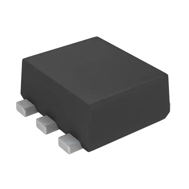
l Outline
VDSS
30V
RDS(on)(Max.)
23.7mΩ
ID
±4.5A
PD
1W
TUMT6
SOT-363T
l Inner circuit
l Features
1) Low on - resistance.
2) High Power Package (TUMT6).
3) Pb-free lead plating ; RoHS compliant.
4) Halogen Free.
l Packaging specifications
Embossed
Tape
Packing
l Application
Type
Switching
Reel size (mm)
Tape width (mm)
180
8
Basic ordering unit (pcs)
Taping code
Marking
3000
TR
CJ
l Absolute maximum ratings (Ta = 25°C)
Parameter
Drain - Source voltage
Continuous drain current
Pulsed drain current
Gate - Source voltage
Power dissipation
Junction temperature
Range of storage temperature
Symbol
Value
Unit
VDSS
ID
30
V
±4.5
±18
±12
1
150
-55 to +150
A
A
V
W
ID,pulse*1
VGSS
PD*2
Tj
Tstg
℃
℃
www.rohm.com
© 2015 ROHM Co., Ltd. All rights reserved.
1/11
20150730 - Rev.002
�
RF6E045AJ
Datasheet
l Thermal resistance
Parameter
Symbol
RthJA*2
Thermal resistance, junction - ambient
Values
Min.
Typ.
Max.
-
-
125
Unit
℃/W
l Electrical characteristics (T a = 25°C)
Parameter
Symbol
Drain - Source breakdown
voltage
Breakdown voltage
temperature coefficient
Conditions
V(BR)DSS VGS = 0V, ID = 1mA
ΔV(BR)DSS ID = 1mA
ΔTj referenced to 25℃
Values
Unit
Min.
Typ.
Max.
30
-
-
V
-
18
-
mV/℃
Zero gate voltage
drain current
IDSS
VDS = 30V, VGS = 0V
-
-
1
μA
Gate - Source leakage current
IGSS
VGS = ±12V, VDS = 0V
-
-
±100
nA
VGS(th)
VDS = VGS, ID = 1mA
0.5
-
1.5
V
-
-2
-
mV/℃
VGS = 4.5V, ID = 4.5A
-
16.9
23.7
VGS = 2.5V, ID = 4.5A
-
23.9
33.5
f = , open drain
-
2.7
-
Ω
VDS = 5V, ID = 4.5A
6
-
-
S
Gate threshold voltage
Gate threshold voltage
temperature coefficient
ΔVGS(th) ID = 1mA
ΔTj referenced to 25℃
Static drain - source
on - state resistance
RDS(on)*3
Gate input resistance
RG
Forward Transfer
Admittance
|Yfs| *3
mΩ
*1 Pw≦10μs , Duty cycle≦1%
*2 Mounted on a ceramic boad (30×30×0.8mm)
*3 Pulsed
www.rohm.com
© 2015 ROHM Co., Ltd. All rights reserved.
2/11
20150730 - Rev.002
�RF6E045AJ
Datasheet
l Electrical characteristics (Ta = 25°C)
Values
Parameter
Symbol
Conditions
Unit
Min.
Typ.
Max.
Input capacitance
Ciss
VGS = 0V
-
900
-
Output capacitance
Coss
VDS = 15V
-
100
-
Reverse transfer capacitance
Crss
f = 1MHz
-
70
-
VDD ⋍ 15V,VGS = 4.5V
-
15
-
tr*3
ID = 2.2A
-
15
-
td(off)*3
RL ⋍ 6.8Ω
-
40
-
tf*3
RG = 10Ω
-
10
-
Turn - on delay time
Rise time
Turn - off delay time
Fall time
td(on)*3
pF
ns
l Gate charge characteristics (Ta = 25°C)
Values
Parameter
Symbol
Total gate charge
Qg*3
Gate - Source charge
Qgs*3
Gate - Drain charge
Qgd*3
Conditions
VDD ⋍ 15V,
ID = 4.5A,
VGS = 4.5V
Unit
Min.
Typ.
Max.
-
8.1
-
-
2.1
-
-
2.0
-
nC
l Body diode electrical characteristics (Source-Drain) (Ta = 25°C)
Values
Parameter
Body diode continuous
forward current
Symbol
Conditions
IS
Unit
Min.
Typ.
Max.
-
-
0.8
A
-
-
18
A
-
-
1.2
V
Ta = 25℃
Body diode
pulse current
ISP*1
Forward voltage
VSD*3
VGS = 0V, IS = 0.8A
www.rohm.com
© 2015 ROHM Co., Ltd. All rights reserved.
3/11
20150730 - Rev.002
�RF6E045AJ
Datasheet
l Electrical characteristic curves
Fig.1 Power Dissipation Derating Curve
Fig.2 Maximum Safe Operating Area
Fig.3 Normalized Transient Thermal
Resistance vs. Pulse Width
Fig.4 Single Pulse Maximum Power
dissipation
www.rohm.com
© 2015 ROHM Co., Ltd. All rights reserved.
4/11
20150730 - Rev.002
�RF6E045AJ
Datasheet
l Electrical characteristic curves
Fig.5 Typical Output Characteristics(I)
Fig.6 Typical Output Characteristics(II)
Fig.7 Breakdown Voltage vs. Junction
Temperature
www.rohm.com
© 2015 ROHM Co., Ltd. All rights reserved.
5/11
20150730 - Rev.002
�RF6E045AJ
Datasheet
l Electrical characteristic curves
Fig.8 Typical Transfer Characteristics
Fig.9 Gate Threshold Voltage vs. Junction
Temperature
Fig.10 Tranceconductance vs. Drain
Current
www.rohm.com
© 2015 ROHM Co., Ltd. All rights reserved.
6/11
20150730 - Rev.002
�RF6E045AJ
Datasheet
l Electrical characteristic curves
Fig.11 Drain Current Derating Curve
Fig.12 Static Drain - Source On - State
Resistance vs. Gate Source Voltage
Fig.13 Static Drain - Source On - State
Resistance vs. Junction Temperature
www.rohm.com
© 2015 ROHM Co., Ltd. All rights reserved.
7/11
20150730 - Rev.002
�RF6E045AJ
Datasheet
l Electrical characteristic curves
Fig.14 Static Drain - Source On - State
Resistance vs. Drain Current(I)
Fig.15 Static Drain - Source On - State
Resistance vs. Drain Current(II)
Fig.16 Static Drain - Source On - State
Resistance vs. Drain Current(III)
www.rohm.com
© 2015 ROHM Co., Ltd. All rights reserved.
8/11
20150730 - Rev.002
�RF6E045AJ
Datasheet
l Electrical characteristic curves
Fig.17 Typical Capacitance vs. Drain Source Voltage
Fig.18 Switching Characteristics
Fig.19 Dynamic Input Characteristics
Fig.20 Source Current vs. Source Drain
Voltage
www.rohm.com
© 2015 ROHM Co., Ltd. All rights reserved.
9/11
20150730 - Rev.002
�RF6E045AJ
Datasheet
l Measurement circuits
Fig.1-1 Switching Time Measurement Circuit
Fig.1-2 Switching Waveforms
Fig.2-1 Gate Charge Measurement Circuit
Fig.2-2 Gate Charge Waveform
l Notice
This product might cause chip aging and breakdown under the large electrified environment.
Please consider to design ESD protection circuit.
www.rohm.com
© 2015 ROHM Co., Ltd. All rights reserved.
10/11
20150730 - Rev.002
�RF6E045AJ
Datasheet
l Dimensions
www.rohm.com
© 2015 ROHM Co., Ltd. All rights reserved.
11/11
20150730 - Rev.002
��
很抱歉,暂时无法提供与“RF6E045AJTCR”相匹配的价格&库存,您可以联系我们找货
免费人工找货- 国内价格
- 5+3.21000
- 50+2.67500
- 150+2.13990
- 500+1.78330
- 国内价格 香港价格
- 1+1.774801+0.22973
- 100+1.60064100+0.20719
- 300+1.26061300+0.16318
- 500+1.18597500+0.15351
- 1000+1.136211000+0.14707
- 4000+1.103034000+0.14278
- 5000+1.094745000+0.14171
- 国内价格
- 1+6.98916
- 10+4.71813
- 100+2.92263
- 250+2.49382
- 500+2.24228
- 1000+2.01949
- 3000+1.75837
- 6000+1.63739
- 9000+1.58229
- 21000+1.47928
- 国内价格
- 1+0.75460
- 200+0.52030
- 1500+0.47410
- 3000+0.44220
- 国内价格 香港价格
- 3000+2.022683000+0.26182
- 6000+1.859606000+0.24071
- 9000+1.776509000+0.22995
- 15000+1.6831315000+0.21787
- 21000+1.6278421000+0.21071
- 30000+1.5741230000+0.20376
- 国内价格 香港价格
- 1+7.525211+0.97406
- 10+5.0808310+0.65766
- 100+3.15151100+0.40793
- 250+2.68883250+0.34804
- 500+2.41820500+0.31301
- 1000+2.173761000+0.28137
- 3000+1.894403000+0.24521
- 6000+1.763456000+0.22826
- 9000+1.702349000+0.22035
- 21000+1.5975821000+0.20679