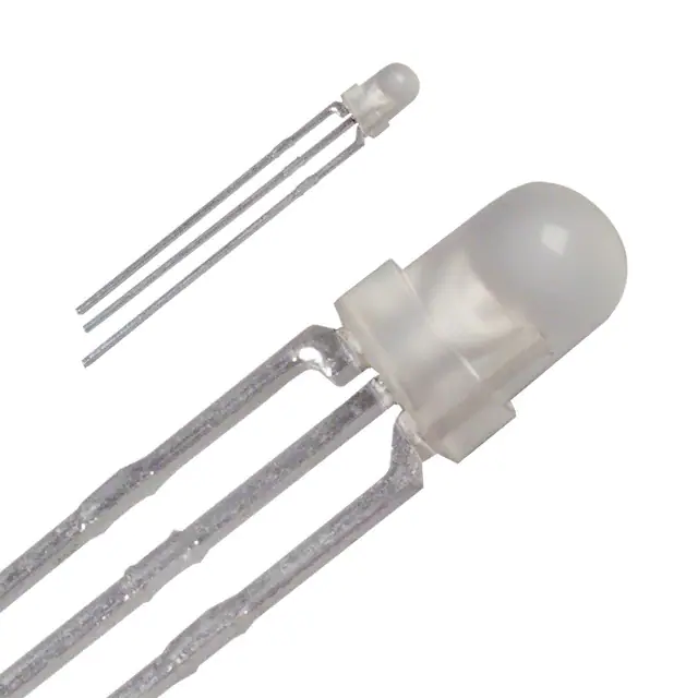
SPR-39 Series
Data Sheet
lFeatures
lOutline
• Viewing angle 2θ 1/2 : 35°
Color
Type
M
V
lRecommended Solder Pattern
lDimensions
1.0
1.5
2.0
2.0
f2.0
Tolerance : 0.2
(unit : mm)
(unit : mm)
lSpecifications
Viewing angle 2θ 1/2 /
35°:Standard
Absolute Maximum Ratings (Ta=25ºC)
Part No.
SPR-39MVW
Chip
Structure
Emitting
Color
GaAsP
on GaP
Red
GaP
Yellowish
Green
Electrical and Optical Characteristics (Ta=25ºC)
Reverse
Operating Temp. Storage Temp.
Dissipation Current
Current Voltage
PD(mW) IF(mA) IFP(mA) VR(V)
Topr(ºC)
Tstg(ºC)
Power Forward
60
Peak Forward
20
Typ.
(V)
IF
Max.
(mA) (mA)
VR
(V)
3
-20 to +85 -30 to +100
25
10
2.1
Typ.
(nm)
100
3
Luminous Intensity IV
IF
IF
Min. Typ.
(mA) (mcd) (mcd) (mA)
650
2.0
60*
75
Forward Voltag VF Reverse Current IR Dominant Wavelength lD
2.2
6.3
3.6
10
10
563
10
*:Duty1/5, 200kHz
*:Individual pieces are not connected together with tapings.
www.rohm.com
© 2014 ROHM Co., Ltd. All rights reserved.
1/6
2014.12 - Rev.B
�Data Sheet
SPR-39 Series
lElectrical Characteristics Curves
Fig.1 Forward Current - Forward Voltages
Fig.2 Luminous Intensity Atmosphere Temperature
RELATIVE LUMINOUS INTENSITY [a.u.]
50
FORWARD CURRENT : IF [mA]
Ta=25ºC
10
1.0
SPR-39MVW(V)
SPR-39MVW(M)
0.1
1.0
1.5
2.0
2.5
3.0
FORWARD VOLTAGE : VF [V]
10
100
MAXIMUM FORWARD CURRENT : IF Max. [mA]
RELATIVE LUMINOUS INTENSITY [a.u.]
Ta=25ºC
1.0
1.0
FORWARD CURRENT : IF [mA]
www.rohm.com
© 2014 ROHM Co., Ltd. All rights reserved.
1.2
1.0
0.8
0.6
SPR-39MVW(V)
SPR-39MVW(M)
0.4
-40
-20
0
20
40
60
80
100
Fig.4 Derating
10
0.1
0.1
IF=20mA
ATMOSPHERE TEMPERATURE : Ta [ºC]
Fig.3 Luminous Intensity - Forward Current
SPR-39MVW(V)
SPR-39MVW(M)
1.4
30
20
10
0
-40
SPR-39MVW(V)
SPR-39MVW(M)
-20
0
20
40
60
80
100
AMBIENT TEMPERATURE : Ta [ºC]
2/6
2014.12 - Rev.B
�Data Sheet
SPR-39 Series
lViewing Angle
Directivity (deg)
X’ -Y’
X -Y
30°
20°
10°
0°
10°
X ‐Y
X’‐Y’
20°
30°
40°
40°
50°
50°
60°
60°
70°
70°
80°
80°
90°
100
50
0
90°
100
50
RELATIVE INTENSITY
lRank Reference of Brightness
Dual Color
Rank
Iv (mcd)
(Ta=25ºC, IF=10mA)
E
F
0.40 to 0.63 0.63 to 1.0
G
H
J
K
L
M
N
P
Q
R
1.0 to 1.6
1.6 to 2.5
2.5 to 4.0
4.0 to 6.3
6.3 to 10
10 to 16
16 to 25
25 to 40
40 to 63
63 to 100
SPR-39MVW
*"SYMBOL" are settled for Green only. For red, we set only min, intensity and not "SYMBOL".
lPart No. Construction
www.rohm.com
© 2014 ROHM Co., Ltd. All rights reserved.
3/6
2014.12 - Rev.B
�SPR-39 Series
Data Sheet
lAttention Points In Handling
Visual light emitting diode does not contain reinforcement materials such as glass fillers.
Therefore if sudden thermal and mechanical shock are given, destruction or inferiority of luminous intensity
may occur. Please take care of the handling.
■FIXATION METHOD
1. ATTENTION POINTS
(1) Please do not give excessive heat over storage temperature to resin.
In case that the product has to be heated in oven for the glue fixing of surface mount pats, this LED should
be mounted after the glue fixing.
(2) Please avoid stress to resin at high temperature.
< Good >
< No good >
2. TERMINATION PROCESSING
To be fixed
To be fixed
(1) In case of termination processing, please fix the
termination
(2) Processing position, and process the reverse side of
LED body.
If stress is given during processing, It may cause
non-lighting failure.
(3) Please process before soldering.
3. ASSEMBLY ON PC BOARD
(1) In case of soldering on PCB, If the operation is done with stress, it may cause non-lighting failure during
soldering or using.
Please design the through-holes of PCB suitable for lead pins space or lead pins space after formin to avoid
the physical stress on resin.
< Good >
< Good >
< No good >
< 2 lead pins type >
< 3 lead pins type >
(2) Using spacer between LED’s body and PCB is recommended.
In case of direct mount on PCB(SLR/SLI-343 series), please take care about clinch of led pins
to avoid the remained stress and solder heat stress.
Enough evaluation is requested before deciding assembly and soldering conditions.
Please consult with us if any problems in the evaluation stage.
< 3 lead pin type >
< 2 lead pin type >
Min.15°
Min.45°
Die bonding side
www.rohm.com
© 2014 ROHM Co., Ltd. All rights reserved.
Min.15°
Min.45°
4/6
Min.45°
Die bonding side
2014.12 - Rev.B
�SPR-39 Series
Data Sheet
4. SOLDERING (Sn-3Ag-0.5Cu)
(1) Please make soldering rapidly under the following temperature and time conditions.
(2) Please avoid stress to LED lamp during soldering.
(3) In case of double peak flow soldering, the temperature gap during 1st and 2nd soldering to be less than 100
degree C.
SOLDERING OPERATION
ARTIICLE
TEMP
TIME
Soldering
Dip
Pre-heat
Max. 100ºC
Soldering
Bath
Max. 265ºC
Soldering Iron
Max. 400ºC
Remarks
60sec Max. In case of double peak flow soldering, the operation
5sec Max. time is counted from the beginning of 1st peak to the
end of 2nd peak.
3sec Max. The iron should not touch the LED’s body.
5. CLEANING
In case of cleaning, some solvents may cause damage of resin or cause non-lighting failure, so please check
the solvent before actual use.
The recommendable cleaning solvent is alcoholic one such as isopropyl alcohol.
METHOD
CONDITIONS
Temperature of
: Max. 45ºC
solvent
Immersion time : Max. 3min
Ultrasonic out : Ultrasonic out
Cleaning time : Max. 3min
Cleaning by solvent
Cleaning by solvent
6. RECOMMENDABLE ROUND PATTERN
Round pattern depends on the material PCB, density and circuit arrangement.
Our recommendation is as follow :
< 2lead pin type >
< 3lead pin type/2.5mm pitch >
±
< 3 lead pin type/2.0mm pitch >
±
±
∗ Unit : mm
∗ Lead types : □0.4mm
□0.5mm
φ
■ATTENTION ON STORAGING
Storage in dry box is most desirable, but if it is not possible, we recommend following conditions.
ARTICLE
Temperature
CONDITIONS
5 to 30ºC
Humidity
Max.60%RH
Expiration Date
Within 1 year
Poor storage conditions may cause some failure as bellow.
(1) Lead pins may corrode if it is stored in the environment of high temperature and humidity and lead to defective
soldering.
(2) In case of soldering after LED’s body absorb moisture highly, destruction or inferiority of luminous intensity
may occur.
www.rohm.com
© 2014 ROHM Co., Ltd. All rights reserved.
5/6
2014.12 - Rev.B
�SPR-39 Series
Data Sheet
■APPLICATION METHOD
1. Precaution for Drive System and Off Mode
• Design the circuit without the electric load exceeding the ABSOLUTE MAXIMUM RATING that applies on the
products.
• If drive by constant voltage, it may cause current deviation of the LED and result in deviation of luminous
intensity, so we recommend to drive by constant current. (Deviation of VF Value will cause deviation of current
in LED.)
• Furthermore, for off mode, please do not apply voltage neither forward nor reverse. Especially, for the products
with the Ag-paste used in the die bonding, there’s high possibility to cause electro migration and result in
function failure.
2. Operation Life Span
There’s possibility for intensity of light drop according to working conditions and environments (applied current,
surrounding temperature and humidity, corrosive gases ), please call our Sales staffs for inquiries about the
concerned application below.
(1) Longtime intensity of light life
(2) On mode all the time
3. Usage
The Product is LED. We are not responsible for the usage as the diode such as Protection Chip, Rectifier,
Switching and so on.
■OTHERS
1. Surrounding Gas
Notice that if it is stored under the condition of acid gas (chlorine gas, sulfured gas) or alkali gas (ammonia),
it may result in low soldering ability (caused by the change in quality of the plating surface ) or optical
characteristics changes (light intensity, chrominance) and change in quality of die bonding (Ag-paste)
aterials.
All of the above will cause function failure of the products.
Therefore, please pay attention to the storage environment for mounted product (concern the generated gas of
the surrounding parts of the products and the atmospheric environment).
2. Electrostatic Damage
The product is part of semiconductor and electrostatic sensitive, there’s high possibility to be damaged by the
electrostatic discharge.
Please take appropriate measures to avoid the static electricity from human body and earthing setting of
production equipment. The resistance values of electrostatic discharge (actual values) are different varies with
products, therefore, please call our Sales staffs for inquiries.
3. Electromagnetic Wave
Please concern the influence on LED in case of application with strong electromagnetic wave such as IH
(Induction heating).
www.rohm.com
© 2014 ROHM Co., Ltd. All rights reserved.
6/6
2014.12 - Rev.B
�Notice
Notes
1) The information contained herein is subject to change without notice.
2) Before you use our Products, please contact our sales representative and verify the latest specifications :
3) Although ROHM is continuously working to improve product reliability and quality, semiconductors can break down and malfunction due to various factors.
Therefore, in order to prevent personal injury or fire arising from failure, please take safety
measures such as complying with the derating characteristics, implementing redundant and
fire prevention designs, and utilizing backups and fail-safe procedures. ROHM shall have no
responsibility for any damages arising out of the use of our Poducts beyond the rating specified by
ROHM.
4) Examples of application circuits, circuit constants and any other information contained herein are
provided only to illustrate the standard usage and operations of the Products. The peripheral
conditions must be taken into account when designing circuits for mass production.
5) The technical information specified herein is intended only to show the typical functions of and
examples of application circuits for the Products. ROHM does not grant you, explicitly or implicitly,
any license to use or exercise intellectual property or other rights held by ROHM or any other
parties. ROHM shall have no responsibility whatsoever for any dispute arising out of the use of
such technical information.
6) The Products are intended for use in general electronic equipment (i.e. AV/OA devices, communication, consumer systems, gaming/entertainment sets) as well as the applications indicated in
this document.
7) The Products specified in this document are not designed to be radiation tolerant.
8) For use of our Products in applications requiring a high degree of reliability (as exemplified
below), please contact and consult with a ROHM representative : transportation equipment (i.e.
cars, ships, trains), primary communication equipment, traffic lights, fire/crime prevention, safety
equipment, medical systems, servers, solar cells, and power transmission systems.
9) Do not use our Products in applications requiring extremely high reliability, such as aerospace
equipment, nuclear power control systems, and submarine repeaters.
10) ROHM shall have no responsibility for any damages or injury arising from non-compliance with
the recommended usage conditions and specifications contained herein.
11) ROHM has used reasonable care to ensur the accuracy of the information contained in this
document. However, ROHM does not warrants that such information is error-free, and ROHM
shall have no responsibility for any damages arising from any inaccuracy or misprint of such
information.
12) Please use the Products in accordance with any applicable environmental laws and regulations,
such as the RoHS Directive. For more details, including RoHS compatibility, please contact a
ROHM sales office. ROHM shall have no responsibility for any damages or losses resulting
non-compliance with any applicable laws or regulations.
13) When providing our Products and technologies contained in this document to other countries,
you must abide by the procedures and provisions stipulated in all applicable export laws and
regulations, including without limitation the US Export Administration Regulations and the Foreign
Exchange and Foreign Trade Act.
14) This document, in part or in whole, may not be reprinted or reproduced without prior consent of
ROHM.
Thank you for your accessing to ROHM product informations.
More detail product informations and catalogs are available, please contact us.
ROHM Customer Support System
http://www.rohm.com/contact/
www.rohm.com
© 2014 ROHM Co., Ltd. All rights reserved.
R1102A
�