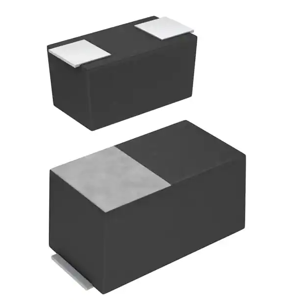
Chip tantalum capacitors
(Bottom surface electrode type : Large capacitance)
TC series M case
Datasheet
●Features
1) Bottom electrode configuration results in significantly greater compactness.
2) Filet formation enables easy visibility after mounting.
3) Ideal for noise removal on power supply lines with limited space.
4) Eco-friendly halogen-free products.
●Dimensions
(Unit: mm)
Dimensions
Size
L
1.6±0.1
W1
0.85±0.1
W2
0.55±0.1
H
0.8±0.1
S
0.5±0.1
●Part No. Explanation
T
C
M
①
②
① Series name
TC
② Case style
M:1608-1608(09)size
③ Rated voltage
CODE
Rated voltage(V)
0E
2.5
0G
4
0J
6.3
1A
10
1C
16
1D
20
1E
25
1V
35
1H
50
www.rohm.com
© 2022 ROHM Co.,Ltd.All rights reserved.
1
A
1
0
③
5
④
M
⑤
8
R -
⑥
⑦
④ Nominal capacitance
Nominal capacitance in pF in 3 digits:
2 significant figures followed by the figure representing
the number of 0's.
⑤ Capacitance tolerance
M:±20%
⑥ Taping
8: Tape width
R: Positive electrode on the side opposite to sprocket hole
⑦ Discrimination code
1/7
2022.6.3 - Rev.005
�TC series M case
Datasheet
●Rated table
Impedance(Ω)
Capacitance
(μF)
Rated voltage (V.DC)
2.5
1.0
(105)
2.2
(225)
3.3
(335)
4.7
(475)
6.8
(685)
10
(106)
15
(156)
22
(226)
33
(336)
47
(476)
68
(686)
100
(107)
150
(157)
220
(227)
4
6.3
10
16
20
25
15
13.5
9
9
9
9
9
35
50
10
13.5
9
9
●Marking
The indications listed below should be given on the surface of a capacitor.
(1) Polarity: The polarity should be shown by bar. (on the anode side)
(2) Rated DC voltage: A voltage code is shown as below table.
(3) Capacitance: A capacitance code is shown as below table.
Voltage Code
e
g
j
A
C
D
E
V
H
Rated DC
Voltage (V)
2.5
4
6.3
10
16
20
25
35
50
Capacitance
Code
E
N
S
A
E
J
N
S
W
a
Nominal
Capacitance (μF)
0.15
0.33
0.47
1.0
1.5
2.2
3.3
4.7
6.8
10
Capacitance
Code
e
j
n
s
w
a
e
j
n
s
Nominal
Capacitance (μF)
15
22
33
47
68
100
150
220
330
470
Visual typical example
voltage code and capacitance code are variable with parts number.
[TC series M case]
EX.)
A
(1)
A
(2)
AA
(1) voltage code
(2) capacitance code
Manufacture code
Anode band
www.rohm.com
© 2022 ROHM Co.,Ltd.All rights reserved.
2/7
冨
2022.6.3 - Rev.005
�TC series M case
Datasheet
●Characteristics
Item
Test conditions
(based on JIS C 5101-1 and JIS C 5101-3)
Performance
Operating Temperature
-55℃~+125℃
Maximum operating
temperature with no
voltage derating
Rated voltage (V.DC)
Category voltage (V.DC)
Surge voltage (V.DC)
DC Leakage current
+85℃
Capacitance tolerance
Shall be satisfied allowance range.
±20%
Tangent of loss angle
(Df,tanδ)
Shall be satisfied the value on
" Standard list ".
Impedance
Shall be satisfied the value on
" Standard list ".
Resistance to
Soldering
heat
Appearance
Refer to " Standard list ".
Refer to " Standard list ".
Refer to " Standard list ".
Shall be satisfied the value on
" Standard list ".
There should be no significant
abnormality.
The indications should be clear.
L.C.
Temperature
cycle
Voltage reduction when temperature exceeds
+85°C
Less than 200% of initial limit.
⊿C/C
Within ±30% of initial value.
DF
(tanδ)
Appearance
Less than 200% of initial limit.
There should be no significant
abnormality.
The indications should be clear.
L.C.
Less than 200% of initial limit.
⊿C/C
Within ±30% of initial value.
DF
(tanδ)
Less than 200% of initial limit.
at 85℃
at 125℃
at 85℃
As per 4.9 JIS C 5101-1
As per 4.5.1 JIS C 5101-3
Voltage : Rated voltage for 5min
As per 4.7 JIS C 5101-1
As per 4.5.2 JIS C 5101-3
Measuring frequency
:120 ± 12Hz
Measuring voltage
:0.5Vrms + 1.5V.DC
Measuring circuit
:DC Equivalent series circuit
As per 4.8 JIS C 5101-1
As per 4.5.3 JIS C 5101-3
Measuring frequency
:120 ± 12Hz
Measuring voltage
:0.5Vrms + 1.5V.DC
Measuring circuit
:DC Equivalent series circuit
As per 4.10 JIS C 5101-1
As per 4.5.4 JIS C 5101-3
Measuring frequency
:100 ± 10kHz
Measuring voltage
:0.5Vrms or less
Measuring circuit
:DC Equivalent series circuit
As per 4.14 JIS C 5101-1
As per 4.6 JIS C 5101-3
Dip in the solder bath
Solder temp
:240 ± 5°C
Duration
:10 ± 0.5s
Repetition
:1
After the specimens, leave it at room temperature
for over 24h and then measure the sample.
As per 4.16 JIS C 5101-1
As per 4.10 JIS C 5101-3
Repetition : 5 cycles
(1 cycle : steps 1 to 4) without discontinuation.
Temp.
Time
1
30±3min
-55±3℃
2
Room Temp.
3min or less
3
30±3min
125±2℃
4
Room Temp.
3min or less
After the specimens, leave it at room temperature
for over 24h and then measure the sample.
Initial value for ⊿C/C shall be the value after
mounted.
www.rohm.com
© 2022 ROHM Co.,Ltd.All rights reserved.
3/7
冨
2022.6.3 - Rev.005
�TC series M case
Datasheet
Item
Moisture
resistance
Test conditions
(based on JIS C 5101-1 and JIS C 5101-3)
Performance
Appearance
There should be no significant
abnormality.
The indications should be clear.
L.C.
Temperature
Stability
Less than 200% of initial limit.
⊿C/C
Within ±30% of initial value.
DF
(tanδ)
Less than 200% of initial limit.
Temp.:-55℃
⊿C/C
Within 0/-30% of initial value.
DF
(tanδ)
L.C.
Shall be satisfied the value on
" Standard list "
As per 4.22 JIS C 5101-1
As per 4.12 JIS C 5101-3
After leaving the sample under such atmospheric
condition that the temperature and humidity are
60±2°C and 90 to 95% RH, respectively, for
500+12/0h leave it at room temperature for
over 24h and then measure the sample.
Initial value for ⊿C/C shall be the value after
mounted.
As per 4.29 JIS C 5101-1
As per 4.13 JIS C 5101-3
Initial value for ⊿C/C shall be the value after
mounted.
-
Temp.:+85℃
⊿C/C
Within +15/-5% of initial value.
DF
(tanδ)
L.C.
Shall be satisfied the value on
" Standard list "
Less than 1000% of initial limit.
Temp.:+125℃
⊿C/C
Within +20/-5% of initial value.
Surge
voltage
DF
(tanδ)
L.C.
Shall be satisfied the value on
" Standard list "
Less than 1250% of initial limit.
Appearance
There should be no significant
abnormality.
The indications should be clear.
L.C.
Loading at
High
temperature
Less than 200% of initial limit.
⊿C/C
Within ±20% of initial value.
DF
(tanδ)
Less than 200% of initial limit.
Appearance
There should be no significant
abnormality.
The indications should be clear.
L.C.
Less than 200% of initial limit.
⊿C/C
Within ±30% of initial value.
DF
(tanδ)
Less than 200% of initial limit.
www.rohm.com
© 2022 ROHM Co.,Ltd.All rights reserved.
4/7
As per 4.26JIS C 5101-1
As per 4.14JIS C 5101-3
Apply the specified surge voltage via the serial
resistance of 1kΩ ever 5±0.5 min. for 30±5 s.
each time in the atmospheric condition of
85±2°C. Repeat this procedure 1,000 times.
After the specimens, leave it at room temperature
for over 24h and then measure the sample.
Initial value for ⊿C/C shall be the value after
mounted.
As per 4.23 JIS C 5101-1
As per 4.15 JIS C 5101-3
After applying the rated voltage for 1000+36/0 h
without discontinuation via the serial resistance
of 3Ω or less at a temperature of 85±2°C, leave
the sample at room temperature / humidity for
over 24h and measure the value.
Initial value for ⊿C/C shall be the value after
mounted.
冨
2022.6.3 - Rev.005
�TC series M case
Item
Terminal
strength
Datasheet
Test conditions
(based on JIS C 5101-1 and JIS C 5101-3)
Performance
Capacitance
Appearance
The measured value should be
stable.
There should be no significant
abnormality.
As per 4.35 JIS C 5101-1
As per 4.9 JIS C 5101-3
A force is applied to the terminal until it bends to
1mm and by a prescribed tool maintains the
condition for 5s.
(See the figure below)
20
50
F(Apply force)
R230
1.0mm
thickness=1.6mm
45
Adhesiveness
The terminal should not come off.
45
As per 4.34 JIS C 5101-1
As per 4.8 JIS C 5101-3
Apply force of 2N in the two directions shown in
the figure below for 10±1s after mounting the
terminal on a circuit board.
Products
Apply force
A circuit board
Dimensions
Refer to "External dimensions".
Resistance to
solvents
The indication should be clear.
Solderability
3/4 or more surface area of the
solder coated terminal dipped in
the soldering bath should be
covered with the new solder.
Vibration
Capacitance
Appearance
www.rohm.com
© 2022 ROHM Co.,Ltd.All rights reserved.
Measure value should not fluctuate
during the measurement.
There should be no significant
abnormality.
5/7
Measure using a caliper of JIS B 7507 Class
2 or higher grade.
As per 4.32 JIS C 5101-1
As per 4.18 JIS C 5101-3
Dip in the isopropyl alcohol for 30±5s, at room
temperature.
As per 4.15.2 JIS C 5101-1
As per 4.7 JIS C 5101-3
Dip speed=25±2.5mm / s
Pre-treatment (accelerated aging):
Leave the sample on the boiling distilled water
for 1h.
Solder temp. : 245±5°C
Duration : 3±0.5s
Solder : M705
Flux : Rosin 25% IPA 75%
As per 4.17 JIS C 5101-1
Frequency : 10 to 55 to 10Hz/min.
Amplitude : 1.5mm
Time : 2h each in X and Y directions
Mounting : The terminal is soldered on a print
circuit board.
冨
2022.6.3 - Rev.005
�TC series M case
Datasheet
●Standard products list
Rated
Category
Surge
voltage
voltage
voltage
85℃
125℃
85℃
Cap.
Tole-
Leakage
tanδ
rance
current
120Hz
120Hz
Impedance
100kHz
25℃
Part No.
1WV
-55℃
25℃ 125℃
5min
(μF)
(%)
(μA)
(%)
(%)
(%)
(Ω)
5
22
±20
0.9
30
20
30
9
8
4.7
±20
0.5
30
20
30
9
4
8
10
±20
0.6
30
20
30
9
6.3
4
8
22
±20
13.0
60
30
40
9
6.3
4
8
33
±20
208.0
60
30
40
9
TCM1A225M8R
10
6.3
13
2.2
±20
0.5
30
20
30
13.5
TCM1A475M8R
10
6.3
13
4.7
±20
0.5
30
20
30
9
TCM1A106M8R
10
6.3
13
10
±20
10.0
30
20
30
9
TCM1C105M8R
16
10
20
1
±20
0.5
15
10
15
15
TCM1C225M8R
16
10
20
2.2
±20
0.5
30
20
30
13.5
TCM1E105M8R
25
16
32
1
±20
0.5
15
10
15
10
(V)
(V)
(V)
TCM0G226M8R
4
2.5
TCM0J475M8R
6.3
4
TCM0J106M8R
6.3
TCM0J226M8R-V1
TCM0J336M8R-V1
www.rohm.com
© 2022 ROHM Co.,Ltd.All rights reserved.
6/7
冨
2022.6.3 - Rev.005
�TC series M case
Datasheet
●Packaging specifications
Sprocket hole φDo
t1
E
A
F
B
W
t2
Component is loaded.
P1
P2
Pull-out direction
PO
Unit[㎜]
A
B
W
E
F
P1
P2
1.00±0.10
1.85±0.10
8.00±0.20
1.75±0.10
3.50±0.05
4.00±0.10
2.00±0.05
PO
DO
t1
t2
Standard packaging quantity
4.00±0.10
φ1.50+0.10/0
0.20±0.05
1.00±0.10
4,000pcs
9.0+1.0/0
●Reel dimensions
φ180+0/-1.5
φ60+1.0/0
φ13±0.2
11.4±1.0
Unit[㎜]
ラベル貼付位置
www.rohm.com
© 2022 ROHM Co.,Ltd.All rights reserved.
引き出し方向
EIAJ ET-7200A
7/7
冨
2022.6.3 - Rev.005
�Notice
Notes
1) The information contained herein is subject to change without notice.
2) Before you use our Products, please contact our sales representative and verify the latest specifications.
3) Although ROHM is continuously working to improve product reliability and quality, semiconductors can break down and malfunction due to various factors.
Therefore, in order to prevent personal injury or fire arising from failure, please take safety
measures such as complying with the derating characteristics, implementing redundant and
fire prevention designs, and utilizing backups and fail-safe procedures. ROHM shall have no
responsibility for any damages arising out of the use of our Poducts beyond the rating specified by
ROHM.
4) Examples of application circuits, circuit constants and any other information contained herein are
provided only to illustrate the standard usage and operations of the Products. The peripheral
conditions must be taken into account when designing circuits for mass production.
5) The technical information specified herein is intended only to show the typical functions of and
examples of application circuits for the Products. ROHM does not grant you, explicitly or implicitly,
any license to use or exercise intellectual property or other rights held by ROHM or any other
parties. ROHM shall have no responsibility whatsoever for any dispute arising out of the use of
such technical information.
6) The Products are intended for use in general electronic equipment (i.e. AV/OA devices, communication, consumer systems, gaming/entertainment sets) as well as the applications indicated in
this document.
7) The Products specified in this document are not designed to be radiation tolerant.
8) For use of our Products in applications requiring a high degree of reliability (as exemplified
below), please contact and consult with a ROHM representative : transportation equipment (i.e.
cars, ships, trains), primary communication equipment, traffic lights, fire/crime prevention, safety
equipment, medical systems, servers, solar cells, and power transmission systems.
9) Do not use our Products in applications requiring extremely high reliability, such as aerospace
equipment, nuclear power control systems, and submarine repeaters.
10) ROHM shall have no responsibility for any damages or injury arising from non-compliance with
the recommended usage conditions and specifications contained herein.
11) ROHM has used reasonable care to ensure the accuracy of the information contained in this
document. However, ROHM does not warrants that such information is error-free, and ROHM
shall have no responsibility for any damages arising from any inaccuracy or misprint of such
information.
12) Please use the Products in accordance with any applicable environmental laws and regulations,
such as the RoHS Directive. For more details, including RoHS compatibility, please contact a
ROHM sales office. ROHM shall have no responsibility for any damages or losses resulting
non-compliance with any applicable laws or regulations.
13) When providing our Products and technologies contained in this document to other countries,
you must abide by the procedures and provisions stipulated in all applicable export laws and
regulations, including without limitation the US Export Administration Regulations and the Foreign
Exchange and Foreign Trade Act.
14) This document, in part or in whole, may not be reprinted or reproduced without prior consent of
ROHM.
Thank you for your accessing to ROHM product informations.
More detail product informations and catalogs are available, please contact us.
ROHM Customer Support System
http://www.rohm.com/contact/
www.rohm.com
© 2015 ROHM Co., Ltd. All rights reserved.
R1107 A
�Datasheet
General Precaution
1. Before you use our Products, you are requested to carefully read this document and fully understand its contents.
ROHM shall not be in any way responsible or liable for failure, malfunction or accident arising from the use of any
ROHM’s Products against warning, caution or note contained in this document.
2. All information contained in this document is current as of the issuing date and subject to change without any prior
notice. Before purchasing or using ROHM’s Products, please confirm the latest information with a ROHM sales
representative.
3.
The information contained in this document is provided on an “as is” basis and ROHM does not warrant that all
information contained in this document is accurate and/or error-free. ROHM shall not be in any way responsible or
liable for an y damages, expenses or losses incurred b y you or third parties resulting from inaccuracy or errors of or
concerning such information.
Notice – WE
© 2015 ROHM Co., Ltd. All rights reserved.
Rev.001
�