November 2015
on Emis
s
arb
ion
1.86g
C
MLCC(02A104M) 1piece
�on Emis
s
arb
ion
1.86g
C
MLCC(02A104M) 1piece
We declare that all our MLCCs are produced in accordance
with EU ROHS and REACH Directive.
1. RoHS Compliance and restriction of Br
The following restricted materials are not used in packaging materials as well as products in compliance with the law and restriction.
- Cd, Pb, Hg, Cr6+, As, Br and the compounds, PCB, asbestos
2. No use of materials breaking Ozone layer
The following ODS materials are not used in our fabrication process.
- ODS material : Freon, Haron, 1-1-1 TCE, CCl4, HCFC
If you want more detailed Information,Please Visit Samsung Electro-mechanics Website
[http://www.semlcr.com]
Please, see the last page of this catalog for our environ mental certification list.
�CONTENTS
Part Numbering System
4
Part Numbering
System
Standard & High Capacitors
6
Standard &
High Capacitors
Super Small Size Capacitors
30
Super Small Size
Capacitors
High-Q Capacitors
35
High-Q
Capacitors
Medium-High Voltage Capacitors
36
Medium-High
Voltage Capacitors
Array Type Capacitors
47
Array Type
Capacitors
Low ESL Capacitors
50
Low ESL
Capacitors
Reliability Test Condition
53
Reliability Test
Condition
Premium Capacitors for Automotive Applications
60
Premium Capacitors
for Automotive
Applications
Packaging Specification
72
Packaging
Specification
Application Manual for Surface Mounting
76
Application Manual
for Surface Mounting
�Part Numbering
System
CL 10
1
2
A 106 M
P
8
N
N
N
C
3
6
7
8
9
10
11
4
5
1. SERIES CODE
CL = Multi layer Ceramic Capacitors
inch(㎜)
2. SIZE CODE
02 = 01005(0402)
03 = 0201(0603)
05 = 0402(1005)
10 = 0603(1608)
21 = 0805(2012)
31 = 1206(3216)
32 = 1210(3225)
42 = 1808(4520)
43 = 1812(4532)
55 = 2220(5750)
★
3. DIELECTRIC CODE
ClassⅠ
ClassⅡ
C = C0G
A = X5R F = Y5V
B = X7R X = X6S
Y = X7S Z = X7T
★★
4. CAPACITANCE CODE
Capacitance expressed in ㎊. 2 significant digits plus number of zeros.
example) 106 =10 106 =10000000㎊
For Values 10 ㎊, Letter R denotes decimal point
example) 1R5 =1.5㎊
5. TOLERANCE CODE
B = 0.1㎊
C = 0.25 ㎊
D = 0.5 ㎊
F = 1㎊, 1%
G= 2%
J = 5%
K = 10%
M = 20%
Z = 80/ 20%
*For Values ≤ 10㎊, F = 1㎊
Values 10㎊, F = 1%
6. RATED VOLTAGE CODE
R = 4V
Q = 6.3V
P = 10V
O = 16V
A = 25V
L = 35V
B = 50V
C = 100V
D = 200V
E = 250V
F = 350V
G = 500V
H = 630V
I = 1000V
J = 2000V
K = 3000V
★★★
7. THICKNESS CODE
2 = 0.20 ㎜
3 = 0.30㎜
5 = 0.50㎜
8 = 0.80㎜
9 = 0.90㎜
A = 0.65㎜ F = 1.25 ㎜
C = 0.85㎜ H = 1.60 ㎜
D = 1.00㎜ I = 2.00㎜
E = 1.10㎜ J = 2.50㎜
L = 3.20 ㎜
M = 1.15 ㎜
P = 1.15 ㎜
Q = 1.25 ㎜
S = 1.35 ㎜
U = 1.80
V = 2.50 ㎜
Y = 1.25 ㎜
8. INNER ELECTRODE/TERMINATION/PLATING CODE
A = Normal Product Pd / Ag / Ni barrier / Sn 100%
N = Normal Product Ni / Cu / Ni barrier / Sn 100%
G = Normal Product Cu / Cu / Ni barrier / Sn 100%
L = Low profile Ni / Cu / Ni barrier / Sn 100%
S = Nomal Product Ni / Cu / Soft termination / Ni barrier / Sn100%
9. PRODUCT CODE
N = Normal
A = Array(4-element)
B = Array(4-element)
L = LICC
J = SLIC
10. CONTROL CODE
*Size tolerance
Size
01005(0402) 0201(0603) 0402(1005) 0603(1608) 0805(2012) 1206(3216)
Code
0.03
0.05
0.07
0.07
0.30
S
0.15
0.05
0.07
0.10
0.15
Q
0.20
0.07
0.09
0.15
0.20
R
0.30
U
0.09
0.20
0.25
Z
0.40
0.30
9
0.30
N= Reserved for future use
11. PACKAGING CODE
B = Bulk
O = Cardboard Tape, 10”Reel
E = Embossed Type, 7”Reel
P = Bulk Case
D = Cardboard Tape, 13”Reel (10,000ea)
G = Embossed Type, 7”Reel (3,000ea)
C= Cardboard Tape, 7”Reel
L = Cardboard Tape, 13”Reel (15,000ea)
F = Embossed Type, 13”Reel
H = Cardboard Tape, 7”Reel (15,000ea)
S = Embossed Type, 10”Reel
8 = Cardboard Tape, 7”Reel
Z = Cardboard Type, 7”Reel (Chip aligned for horizontal SMT)
Y = Cardboard Type, 7”Reel (Chip aligned for vertical SMT)
�Class I (Temperature Compensation)
Symbol
EIA Code
C
C0G
Operation Temperature Range( ℃)
55
Temperature Coefficient Range(ppm/℃)
0 30
125
★
Class ll (High Dielectric Constant)
Symbol
EIA Code
A
B
X
F
Y
Z
X5R
X7R
X6S
Y5V
X7S
X7T
Operation Temperature Range( ℃)
55
55
55
30
55
55
Capacitance Change(△℃%)
85
125
105
85
125
125
15
15
22
82
Part Numbering
System
Standard &
High Capacitors
22
22
33
Super Small Size
Capacitors
22
★★
Series
TC
E-3
Y5V
X5R
X7R
X6S
X7S
X7T
C0G
E-6
E-12
Capacitance Step
1.0
1.0
1.5
1.2
1.5
2.2
1.8
2.2
3.3
2.7
High-Q
Capacitors
4.7
2.2
1.0
3.3
4.7
3.9
4.7
Medium-High
Voltage Capacitors
6.8
5.6
6.8
8.2
Array Type
Capacitors
★★★
Size
Code
Thickness(mm)
01005(0402)
0201(0603)
2
3
3
5
5
8
A
C
C
M
F
Q
Y
C
C
E
E
P
M
F
H
0.20
0.30
0.30
0.50
0.50
0.80
0.65
0.85
0.85
1.15
1.25
1.25
1.25
0.85
0.85
1.10
1.10
1.15
1.15
1.25
1.60
0402(1005)
0603(1608)
0805(2012)
1206(3216)
Spec(mm)
0.02
0.03
0.03*
0.05
0.0/ 0.1*
0.10
0.10
0.10
0.10*
0.10
0.10
0.15
0.20
0.15
0.10*
0.15
0.10*
0.10*
0.15
0.15
0.20
Size
1210(3225)
1808(4520)
1812(4532)
2220(5750)
Code
C
9
F
S
H
U
I
J
V
F
H
I
F
H
I
J
L
H
I
J
L
Thickness(mm)
0.85
0.90
1.25
1.35
1.60
1.80
2.00
2.50
2.50
1.25
1.60
2.00
1.25
1.60
2.00
2.50
3.20
1.60
2.00
2.50
3.00
Spec(mm)
0.10*
0.10*
0.20
0.15
0.20
0.20*
0.20
0.20
0.30
0.20
0.20
0.20
0.20
0.20
0.20
0.20
0.30
0.20
0.20
0.20
0.30
Low ESL
Capacitors
Reliability Test
Condition
Premium Capacitors
for Automotive
Applications
Packaging
Specification
Application Manual
for Surface Mounting
th
■ * Mark is only applicable to “L”code, 12 code in part number.
■ Please discuss with sales person with regard to Pd products.
4
5
�Standard & High Capacitors
Feature
t Wide selection of size : from 0402 to 2220
t Highly reliable tolerance and high speed automatic chip placement on PCBs
t Wide capacitance range
t Wide temperature compensation and voltage range
: from C0G to Y5V and from 6.3V to 50V
t Highly reliable performance
t Highly resistant termination metal
t Tape & reel for surface mount assembly
Application
t HHP, DSC, DVC, LCD, TV, Memory Module, PDA, Game Machine
t Tuner (Product code C is suitable.)
t Desktop PC, Note PC, HHP, DC-DC Converter, DSC
Structure and Dimensions
L
W
T
BW
Size Code
EIA Code
05
0402
10
0603
21
0805
31
1206
32
1210
42
1808
43
1812
55
2220
Dimension(mm)
L
1.00
1.60
1.60
2.00
2.00
2.00
2.00
2.00
3.20
3.20
3.20
3.20
3.20
3.20
3.20
3.20
3.20
3.20
3.20
3.20
3.20
4.50
4.50
4.50
4.50
4.50
4.50
5.70
5.70
■ * Mark is only applicable to “L”code, 12
th
W
0.05
0.10
0.10
0.10
0.10
0.10
0.15
0.20
0.20
0.15
0.20
0.20
0.15
0.20
0.30
0.30
0.30
0.30
0.30
0.30
0.40
0.40
0.40
0.40
0.40
0.40
0.40
0.40
0.40
0.50
0.80
0.80
1.25
1.25
1.25
1.25
1.25
1.60
1.60
1.60
1.60
1.60
1.60
2.50
2.50
2.50
2.50
2.50
2.50
2.50
2.00
2.00
2.00
3.20
3.20
3.20
5.00
5.00
code in part number.
0.05
0.10
0.10
0.10
0.10
0.10
0.15
0.20
0.20
0.15
0.20
0.20
0.15
0.20
0.20
0.20
0.20
0.20
0.20
0.20
0.30
0.20
0.20
0.20
0.30
0.30
0.30
0.40
0.40
T
Thickness Code
BW
0.50 0.05
0.50 0.0/ 0.1(*)
0.80 0.10
0.85 0.10
1.15 0.10
1.25 0.10
1.25 0.15
1.25 0.20
0.60 0.10(*)
0.85 0.15
0.85 0.10(*)
1.15 0.10(*)
1.25 0.15
1.60 0.20
0.85 0.10(*)
0.90 0.10(*)
1.60 0.20
1.80 0.20(*)
2.00 0.20
2.50 0.20
2.50 0.30
1.25 0.20
1.40 0.20
2.00 0.20
1.25 0.20
2.50 0.20
3.20 0.30
2.50 0.20
3.20 0.30
5
5
8
C
M
F
Q
0.25 0.10
Y
6
C
C
P
F
H
C
9
H
U
I
J
V
F
G
I
F
J
L
J
L
0.30 0.20
0.5 0.2/ 0.3
0.50 0.30
0.60 0.30
0.80 0.30
0.80 0.30
1.00 0.30
�Standard & High Capacitance (C0G)
Capacitance
Size(mm)
㎊
Vr(V)
0.5 1
㎋
10 22 47 100 220 330 470 560 1 2.2 3.3 4.7 6.8 10 22
27 33 47 68 100 120 150
25
0402(1005)
Part Numbering
System
50
25
0603(1608)
Standard &
High Capacitors
50
25
0805(2012)
50
Super Small Size
Capacitors
16
1206(3216)
25
High-Q
Capacitors
50
1210(3225)
1812(4532)
50
Medium-High
Voltage Capacitors
25
50
2220(5750)
50
43nF
130nF
Array Type
Capacitors
Low ESL
Capacitors
Reliability Test
Condition
Premium Capacitors
for Automotive
Applications
Packaging
Specification
Application Manual
for Surface Mounting
6
7
�Standard & High Capacitance (X5R)
Capacitance (㎌)
Size(mm)
Vr(V)
4
0.1
0.22
0.47
1
2.2
4.7
10
22
47
100
15
6.3
0402(1005)
10
16
25
4
6.3
10
0603(1608)
16
25
50
4
6.3
10
0805(2012)
16
25
50
6.3
10
1206(3216)
16
25
50
6.3
1210(3225)
10
16
25
150
220
�Standard & High Capacitance-Low Profile (X5R)
Size(mm)
Tmax
(mm)
Capacitance (㎌)
Vr(V)
6.3
0402(1005)
0.33
1
2.2
4.7
10
22
47
(Tmax=0.35)
X6S
10
Part Numbering
System
16
6.3
0603(1608)
Standard &
High Capacitors
10
0.5
16
25
Super Small Size
Capacitors
10
0.7
16
High-Q
Capacitors
25
0.85
0805(2012)
0.95
25
4
(Tmax=1.0)
6.3
(Tmax=1.0)
Medium-High
Voltage Capacitors
Array Type
Capacitors
10
16
25
0.7
X6S
10
6.3
Reliability Test
Condition
10
1206(3216)
0.95
0.95
16
25
(Tmax=1.0)
100
(Tmax=1.0)
25
1210(3225)
2.0
X6S
50
16
35
Low ESL
Capacitors
(Tmax=1.0)
Premium Capacitors
for Automotive
Applications
Packaging
Specification
Application Manual
for Surface Mounting
50
8
9
�Standard & High Capacitance (X6S)
Capacitance (㎌)
Size(mm)
Vr(V)
4
0402(1005)
6.3
10
4
6.3
0603(1608)
10
16
25
4
6.3
0805(2012)
10
16
25
6.3
1206(3216)
10
16
25
6.3
1210(3225)
10
16
25
0.1
0.22
0.47
1
2.2
4.7
10
22
47
100
�Standard & High Capacitance (X7R)
Capacitance (㎌)
Size(mm)
Vr(V)
0.1
0.22
0.47
1
2.2
4.7
10
22
47
100
6.3
0402(1005)
10
X7S
Part Numbering
System
16
6.3
Standard &
High Capacitors
10
0603(1608)
16
25
Super Small Size
Capacitors
50
6.3
High-Q
Capacitors
10
16
0805(2012)
25
Medium-High
Voltage Capacitors
X7S
35
Array Type
Capacitors
50
6.3
10
1206(3216)
Low ESL
Capacitors
16
25
Reliability Test
Condition
35
50
6.3
X7T
Premium Capacitors
for Automotive
Applications
10
1210(3225)
16
25
50
Packaging
Specification
Application Manual
for Surface Mounting
10
11
�High Capacitance
Standard
& High capacitance
Table (Y5V)
(Y5V)
Capacitance (㎌)
Size(mm)
Vr(V)
0.1
0.22
0.47
1
2.2
4.7
10
22
47
6.3
10
0402(1005)
16
25
6.3
10
0603(1608)
16
25
50
6.3
10
0805(2012)
16
25
50
10
1206(3216)
16
25
(Tmax=1.35)
50
6.3
(Tmax=2.7)
10
(Tmax=2.0)
(Tmax=1.2)
16
1210(3225)
(Tmax=1.8)
25
(Tmax=1.5)
(Tmax=1.4)
35
(Tmax=1.6)
(Tmax=1.45)
50
Standard & High capacitance - Low Profile (Y5V)
Size(mm)
0805(2012)
Vr(V)
Capacitance (㎌)
1
2.2
4.7
10
6.3
(Tmax=0.95)
10
(Tmax=0.95)
22
47
�Product Lineup (Standard & High Capacitors-C0G)
Part Number
1
2
3
4
5
6
7
8
9
10
11
12
13
14
15
16
17
18
19
20
21
22
23
24
25
26
27
28
29
30
31
32
33
34
35
36
37
38
39
40
41
42
43
44
45
46
47
48
49
50
※
CL05C0R5CB5NNN
CL05CR75CB5NNN
CL05C010CB5NNN
CL05C1R2CB5NNN
CL05C1R5CB5NNN
CL05C1R8CB5NNN
CL05C020CB5NNN
CL05C2R2CB5NNN
CL05C2R4CB5NNN
CL05C2R5CB5NNN
CL05C2R7CB5NNN
CL05C030CB5NNN
CL05C3R3CB5NNN
CL05C3R5CB5NNN
CL05C3R6CB5NNN
CL05C3R9CB5NNN
CL05C040CB5NNN
CL05C4R3CB5NNN
CL05C4R7CB5NNN
CL05C050DB5NNN
CL05C5R6DB5NNN
CL05C060DB5NNN
CL05C6R2DB5NNN
CL05C6R8DB5NNN
CL05C070DB5NNN
CL05C080DB5NNN
CL05C8R2DB5NNN
CL05C090DB5NNN
CL05C9R1DB5NNN
CL05C10 0 J B 5NNN
CL05C110 J B 5NNN
CL05C120 J B5NNN
CL05C130 J B 5NNN
CL05C150 J B 5NNN
CL05C160 J B 5NNN
CL05C180 J B 5NNN
CL05C200 J B 5NNN
CL05C220 J A5NNN
CL05C220 J B 5NNN
CL05C240 J B 5NNN
CL05C270 J B 5NNN
CL05C270 J A5NNN
CL05C300 J B 5NNN
CL05C330 J B 5NNN
CL05C360 J B 5NNN
CL05C390 J B 5NNN
CL05C430 J B 5NNN
CL05C470 J B 5NNN
CL05C510 J B 5NNN
CL05C560 J B 5NNN
Size L x W
(mm)
Capacitance
Rated
Voltage
(Vdc)
1.00 0.50
0.5㎊
0.75 ㎊
1.0 ㎊
1.2 ㎊
1.5 ㎊
1.8 ㎊
2.0 ㎊
2.2 ㎊
2.4 ㎊
2.5 ㎊
2.7 ㎊
3.0 ㎊
3.3 ㎊
3.5 ㎊
3.6 ㎊
3.9 ㎊
4.0 ㎊
4.3 ㎊
4.7 ㎊
5.0 ㎊
5.6 ㎊
6.0 ㎊
6.2 ㎊
6.8 ㎊
7.0 ㎊
8.0 ㎊
8.2 ㎊
9.0 ㎊
9.1 ㎊
10 ㎊
11 ㎊
12 ㎊
13 ㎊
15 ㎊
16 ㎊
18 ㎊
20 ㎊
22 ㎊
22 ㎊
24 ㎊
27 ㎊
27 ㎊
30 ㎊
33 ㎊
36 ㎊
39 ㎊
43 ㎊
47 ㎊
51 ㎊
56 ㎊
50
50
50
50
50
50
50
50
50
50
50
50
50
50
50
50
50
50
50
50
50
50
50
50
50
50
50
50
50
50
50
50
50
50
50
50
50
25
50
50
50
25
50
50
50
50
50
50
50
50
Capacitance
Tolerance
0.25 ㎊
0.25 ㎊
0.25 ㎊
0.25 ㎊
0.25 ㎊
0.25 ㎊
0.25 ㎊
0.25 ㎊
0.25 ㎊
0.25 ㎊
0.25 ㎊
0.25 ㎊
0.25 ㎊
0.25 ㎊
0.25 ㎊
0.25 ㎊
0.25 ㎊
0.25 ㎊
0.25 ㎊
0.5 ㎊
0.5 ㎊
0.5 ㎊
0.5 ㎊
0.5 ㎊
0.5 ㎊
0.5 ㎊
0.5 ㎊
0.5 ㎊
0.5 ㎊
5%
5%
5%
5%
5%
5%
5%
5%
5%
5%
5%
5%
5%
5%
5%
5%
5%
5%
5%
5%
5%
Thickness
Max.(mm)
0.55
0.55
0.55
0.55
0.55
0.55
0.55
0.55
0.55
0.55
0.55
0.55
0.55
0.55
0.55
0.55
0.55
0.55
0.55
0.55
0.55
0.55
0.55
0.55
0.55
0.55
0.55
0.55
0.55
0.55
0.55
0.55
0.55
0.55
0.55
0.55
0.55
0.55
0.55
0.55
0.55
0.55
0.55
0.55
0.55
0.55
0.55
0.55
0.55
0.55
Part Numbering
System
Standard &
High Capacitors
Super Small Size
Capacitors
High-Q
Capacitors
Medium-High
Voltage Capacitors
Array Type
Capacitors
Low ESL
Capacitors
Reliability Test
Condition
Premium Capacitors
for Automotive
Applications
Packaging
Specification
Application Manual
for Surface Mounting
mark means packaging code. If you want to learn the code or quantity in detail, please see p74.
12
13
�Product Lineup (Standard & High Capacitors-C0G)
Part Number
51
52
53
54
55
56
57
58
59
60
61
62
63
64
65
66
67
68
69
70
71
1
2
3
4
5
6
7
8
9
10
11
12
13
14
15
16
17
18
19
20
21
22
23
24
25
26
27
28
29
※
CL05C620 J B 5NNN
CL05C680 J B 5NNN
CL05C750 J B 5NNN
CL05C820 J B 5NNN
CL05C910 J B 5NNN
CL05C101 J B 5NNN
CL05C121 J B 5NNN
CL05C151 J B 5NNN
CL05C181 J B 5NNN
CL05C201 J B 5NNN
CL05C221 J B 5NNN
CL05C271 J B 5NNN
CL05C331 J B 5NNN
CL05C391 J B 5NNN
CL05C471 J B 5NNN
CL05C471 J O5NNN
CL05C681 J B 5NNN
CL05C821 J B 5NNN
CL05C102 J B 5NNN
CL05C102 J A5NNN
CL05C102 J O5NNN
CL10C0R3CB8NNN
CL10C0R5CB8NNN
CL10CR75CB8NNN
CL10C010CB8NNN
CL10C1R2CB8NNN
CL10C1R5CB8NNN
CL10C1R8CB8NNN
CL10C020CB8NNN
CL10C2R2CB8NNN
CL10C2R4CB8NNN
CL10C2R5CB8NNN
CL10C2R7CB8NNN
CL10C030CB8NNN
CL10C3R3CB8NNN
CL10C3R5CB8NNN
CL10C3R6CB8NNN
CL10C3R9CB8NNN
CL10C040CB8NNN
CL10C4R3CB8NNN
CL10C4R7CB8NNN
CL10C050DB8NNN
CL10C5R6DB8NNN
CL10C060DB8NNN
CL10C6R2DB8NNN
CL10C6R8DB8NNN
CL10C070DB8NNN
CL10C7R5DB8NNN
CL10C080DB8NNN
CL10C8R2DB8NNN
Size L x W
(mm)
1.00 0.50
1.60 0.80
Capacitance
Rated
Voltage
(Vdc)
62㎊
68㎊
75㎊
82㎊
91㎊
100㎊
120㎊
150㎊
180㎊
200㎊
220㎊
270㎊
330㎊
390㎊
470㎊
470㎊
680㎊
820㎊
1㎋
1㎋
1㎋
0.3㎊
0.5㎊
0.75㎊
1.0㎊
1.2㎊
1.5㎊
1.8㎊
2.0㎊
2.2㎊
2.4㎊
2.5㎊
2.7㎊
3.0㎊
3.3㎊
3.5㎊
3.6㎊
3.9㎊
4.0㎊
4.3㎊
4.7㎊
5.0㎊
5.6㎊
6.0㎊
6.2㎊
6.8㎊
7.0㎊
7.5㎊
8.0㎊
8.2㎊
50
50
50
50
50
50
50
50
50
50
50
50
50
50
50
16
50
50
50
25
16
50
50
50
50
50
50
50
50
50
50
50
50
50
50
50
50
50
50
50
50
50
50
50
50
50
50
50
50
50
Capacitance
Tolerance
mark means packaging code. If you want to learn the code or quantity in detail, please see p74.
5%
5%
5%
5%
5%
5%
5%
5%
5%
5%
5%
5%
5%
5%
5%
5%
5%
5%
5%
5%
5%
0.25㎊
0.25㎊
0.25㎊
0.25㎊
0.25㎊
0.25㎊
0.25㎊
0.25㎊
0.25㎊
0.25㎊
0.25㎊
0.25㎊
0.25㎊
0.25㎊
0.25㎊
0.25㎊
0.25㎊
0.25㎊
0.25㎊
0.25㎊
0.5㎊
0.5㎊
0.5㎊
0.5㎊
0.5㎊
0.5㎊
0.5㎊
0.5㎊
0.5㎊
Thickness
Max.(mm)
0.55
0.55
0.55
0.55
0.55
0.55
0.55
0.55
0.55
0.55
0.55
0.55
0.55
0.55
0.55
0.55
0.55
0.55
0.55
0.55
0.55
0.90
0.90
0.90
0.90
0.90
0.90
0.90
0.90
0.90
0.90
0.90
0.90
0.90
0.90
0.90
0.90
0.90
0.90
0.90
0.90
0.90
0.90
0.90
0.90
0.90
0.90
0.90
0.90
0.90
�Product Lineup (Standard & High Capacitors-C0G)
Part Number
30
31
32
33
34
35
36
37
38
39
40
41
42
43
44
45
46
47
48
49
50
51
52
53
54
55
56
57
58
59
60
61
62
63
64
65
66
67
68
69
70
71
72
73
74
75
76
77
78
79
※
Size L x W
(mm)
CL10C090DB8NNN
CL10C9R1DB8NNN
CL10C100JB8NNN
CL10C110JB8NNN
CL10C120JB8NNN
CL10C130JB8NNN
CL10C140JB8NNN
CL10C150JB8NNN
CL10C160JB8NNN
CL10C180JB8NNN
CL10C200JB8NNN
CL10C220JB8NNN
CL10C240JB8NNN
CL10C250JB8NNN
CL10C270JB8NNN
CL10C300JB8NNN
CL10C330JB8NNN
CL10C360JB8NNN
CL10C390JB8NNN
CL10C430JB8NNN
CL10C470JB8NN N
CL10C510JB8NNN
CL10C560JB8NNN
CL10C620JB8NNN
CL10C680JB8NNN
CL10C750JB8NNN
CL10C820JB8NNN
CL10C910JB8NNN
CL10C101JB8NNN
CL10C111JB8NNN
CL10C121JB8NNN
CL10C131JB8NNN
CL10C151JB8NNN
CL10C161JB8NNN
CL10C181JB8NNN
CL10C201JB8NNN
CL10C221JB8NNN
CL10C241JB8NNN
CL10C271JB8NNN
CL10C301JB8NNN
CL10C331JB8NNN
CL10C361JB8NNN
CL10C391JB8NNN
CL10C431JB8NNN
CL10C471JB8NNN
CL10C511JB8NNN
CL10C561JB8NNN
CL10C621JB8NNN
CL10C681JB8NNN
CL10C751JB8NNN
1.60 0.80
Capacitance
Rated
Voltage
(Vdc)
9.0 ㎊
9.1 ㎊
10 ㎊
11 ㎊
12 ㎊
13 ㎊
14 ㎊
15 ㎊
16 ㎊
18 ㎊
20 ㎊
22 ㎊
24 ㎊
25 ㎊
27 ㎊
30 ㎊
33 ㎊
36 ㎊
39 ㎊
43 ㎊
47 ㎊
51 ㎊
56 ㎊
62 ㎊
68 ㎊
75 ㎊
82 ㎊
91 ㎊
100 ㎊
110 ㎊
120 ㎊
130 ㎊
150 ㎊
160 ㎊
180 ㎊
200 ㎊
220 ㎊
240 ㎊
270 ㎊
300 ㎊
330 ㎊
360 ㎊
390 ㎊
430 ㎊
470 ㎊
510 ㎊
560 ㎊
620 ㎊
680 ㎊
750 ㎊
50
50
50
50
50
50
50
50
50
50
50
50
50
50
50
50
50
50
50
50
50
50
50
50
50
50
50
50
50
50
50
50
50
50
50
50
50
50
50
50
50
50
50
50
50
50
50
50
50
50
Capacitance
Tolerance
0.5㎊
0.5㎊
5%
5%
5%
5%
5%
5%
5%
5%
5%
5%
5%
5%
5%
5%
5%
5%
5%
5%
5%
5%
5%
5%
5%
5%
5%
5%
5%
5%
5%
5%
5%
5%
5%
5%
5%
5%
5%
5%
5%
5%
5%
5%
5%
5%
5%
5%
5%
5%
Thickness
Max.(mm)
0.90
0.90
0.90
0.90
0.90
0.90
0.90
0.90
0.90
0.90
0.90
0.90
0.90
0.90
0.90
0.90
0.90
0.90
0.90
0.90
0.90
0.90
0.90
0.90
0.90
0.90
0.90
0.90
0.90
0.90
0.90
0.90
0.90
0.90
0.90
0.90
0.90
0.90
0.90
0.90
0.90
0.90
0.90
0.90
0.90
0.90
0.90
0.90
0.90
0.90
Part Numbering
System
Standard &
High Capacitors
Super Small Size
Capacitors
High-Q
Capacitors
Medium-High
Voltage Capacitors
Array Type
Capacitors
Low ESL
Capacitors
Reliability Test
Condition
Premium Capacitors
for Automotive
Applications
Packaging
Specification
Application Manual
for Surface Mounting
mark means packaging code. If you want to learn the code or quantity in detail, please see p74.
14
15
�Product Lineup (Standard & High Capacitors-C0G)
Part Number
80
81
82
83
84
85
1
2
3
4
5
6
7
8
9
10
11
12
13
14
15
16
17
18
19
20
21
22
23
24
25
26
27
28
29
30
31
32
33
34
35
36
37
38
39
40
41
42
43
44
45
※
CL10C821 J B 8NNN
CL10C102 J B 8NNN
CL10C182 J B 8NN N
CL10C222 J B 8NNN
CL10C562 J B 8NNN
CL10C103J A 8NNN
CL21CR47CBANNN
CL21C0R5CBANNN
CL21C010CBANNN
CL21C1R2CBANNN
CL21C1R5CBANNN
CL21C1R8CBANNN
CL21C020CBANNN
CL21C2R2CBANNN
CL21C2R4CBANNN
CL21C2R5CBANNN
CL21C2R7CBANNN
CL21C030CBANNN
CL21C3R2CBANNN
CL21C3R3CBANNN
CL21C3R6CBANNN
CL21C3R9CBANNN
CL21C040CBANNN
CL21C4R7CBANNN
CL21C5R6DBANNN
CL21C060DBANNN
CL21C6R8DBANNN
CL21C070DBANNN
CL21C7R5DBANNN
CL21C080DBANNN
CL21C8R2DBANNN
CL21C090DBANNN
CL21C100JBANNN
CL21C120JBANNN
CL21C130JBANNN
CL21C140JBANNN
CL21C150JBANNN
CL21C160JBANNN
CL21C180JBANNN
CL21C200JBANNN
CL21C220JBANNN
CL21C240JBANNN
CL21C250JBANNN
CL21C270JBANNN
CL21C300JBANNN
CL21C330JBANNN
CL21C360JBANNN
CL21C390JBANNN
CL21C430JBANNN
CL21C470JBANNN
CL21C510JBANNN
Size L x W
(mm)
1.60 0.80
2.00 1.25
Capacitance
Rated
Voltage
(Vdc)
820 ㎊
1㎋
1.8 ㎋
2.2 ㎋
5.6 ㎋
10 ㎋
0.47㎊
0.5 ㎊
1.0 ㎊
1.2 ㎊
1.5 ㎊
1.8 ㎊
2.0 ㎊
2.2 ㎊
2.4 ㎊
2.5 ㎊
2.7 ㎊
3.0 ㎊
3.2 ㎊
3.3 ㎊
3.6 ㎊
3.9 ㎊
4.0 ㎊
4.7 ㎊
5.6 ㎊
6.0 ㎊
6.8 ㎊
7.0 ㎊
7.5 ㎊
8.0 ㎊
8.2 ㎊
9.0 ㎊
10 ㎊
12 ㎊
13 ㎊
14 ㎊
15 ㎊
16 ㎊
18 ㎊
20 ㎊
22 ㎊
24 ㎊
25 ㎊
27 ㎊
30 ㎊
33 ㎊
36 ㎊
39 ㎊
43 ㎊
47 ㎊
51 ㎊
50
50
50
50
50
25
50
50
50
50
50
50
50
50
50
50
50
50
50
50
50
50
50
50
50
50
50
50
50
50
50
50
50
50
50
50
50
50
50
50
50
50
50
50
50
50
50
50
50
50
50
Capacitance
Tolerance
mark means packaging code. If you want to learn the code or quantity in detail, please see p74.
5%
5%
5%
5%
5%
5%
0.25 ㎊
0.25 ㎊
0.25 ㎊
0.25 ㎊
0.25 ㎊
0.25 ㎊
0.25 ㎊
0.25 ㎊
0.25 ㎊
0.25 ㎊
0.25 ㎊
0.25 ㎊
0.25 ㎊
0.25 ㎊
0.25 ㎊
0.25 ㎊
0.25 ㎊
0.25 ㎊
0.5 ㎊
0.5 ㎊
0.5 ㎊
0.5 ㎊
0.5 ㎊
0.5 ㎊
0.5 ㎊
0.5 ㎊
5%
5%
5%
5%
5%
5%
5%
5%
5%
5%
5%
5%
5%
5%
5%
5%
5%
5%
5%
Thickness
Max.(mm)
0.90
0.90
0.90
0.90
0.90
0.90
0.75
0.75
0.75
0.75
0.75
0.75
0.75
0.75
0.75
0.75
0.75
0.75
0.75
0.75
0.75
0.75
0.75
0.75
0.75
0.75
0.75
0.75
0.75
0.75
0.75
0.75
0.75
0.75
0.75
0.75
0.75
0.75
0.75
0.75
0.75
0.75
0.75
0.75
0.75
0.75
0.75
0.75
0.75
0.75
0.75
�Product Lineup (Standard & High Capacitors-C0G)
Part Number
46
47
48
49
50
51
52
53
54
55
56
57
58
59
60
61
62
63
64
65
66
67
68
69
70
71
72
73
74
75
76
77
78
79
80
81
82
83
84
85
86
87
88
1
2
3
4
5
6
7
※
CL21C560JBANNN
CL21C620JBANNN
CL21C680JBANNN
CL21C750JBANNN
CL21C820JBANNN
CL21C910JBANNN
CL21C101JBANNN
CL21C111JBANNN
CL21C121JBANNN
CL21C131JBANNN
CL21C151JBANNN
CL21C161JBANNN
CL21C181JBANNN
CL21C201JBANNN
CL21C221JBANNN
CL21C241JBANNN
CL21C271JBANNN
CL21C301JBANNN
CL21C331JBANNN
CL21C361JBANNN
CL21C391JBANNN
CL21C431JBANNN
CL21C471JBANNN
CL21C511JBANNN
CL21C561JBANNN
CL21C621JBCNNN
CL21C681JBCNNN
CL21C751JBCNNN
CL21C821JBCNNN
CL21C102JBCNNN
CL21C122JBFNNN
CL21C152JBFNNN
CL21C182JBFNNN
CL21C222JBFNNN
CL21C332JAFNNN
CL21C332JBFNNN
CL21C392JAANNN
CL21C392JBFNNN
CL21C472JBFNNN
CL21C562JBFNNN
CL21C822JAFNNN
CL21C103JBFNNN
CL21C333JAFNNN
CL31C0R5CBCNNN
CL31C010CBCNNN
CL31C1R5CBCNNN
CL31C1R8CBCNNN
CL31C020CBCNNN
CL31C2R2CBCNNN
CL31C2R7CBCNNN
Size L x W
(mm)
2.00 1.25
3.20 1.60
Capacitance
Rated
Voltage
(Vdc)
56 ㎊
62 ㎊
68 ㎊
75 ㎊
82 ㎊
91 ㎊
100 ㎊
110 ㎊
120 ㎊
130 ㎊
150 ㎊
160 ㎊
180 ㎊
200 ㎊
220 ㎊
240 ㎊
270 ㎊
300 ㎊
330 ㎊
360 ㎊
390 ㎊
430 ㎊
470 ㎊
510 ㎊
560 ㎊
620 ㎊
680 ㎊
750 ㎊
820 ㎊
1㎋
1.2 ㎋
1.5 ㎋
1.8 ㎋
2.2 ㎋
3.3 ㎋
3.3 ㎋
3.9 ㎋
3.9 ㎋
4.7 ㎋
5.6 ㎋
8.2 ㎋
10 ㎋
33 ㎋
0.5 ㎊
1.0 ㎊
1.5 ㎊
1.8 ㎊
2.0 ㎊
2.2 ㎊
2.7 ㎊
50
50
50
50
50
50
50
50
50
50
50
50
50
50
50
50
50
50
50
50
50
50
50
50
50
50
50
50
50
50
50
50
50
50
25
50
25
50
50
50
25
50
25
50
50
50
50
50
50
50
Capacitance
Tolerance
5%
5%
5%
5%
5%
5%
5%
5%
5%
5%
5%
5%
5%
5%
5%
5%
5%
5%
5%
5%
5%
5%
5%
5%
5%
5%
5%
5%
5%
5%
5%
5%
5%
5%
5%
5%
5%
5%
5%
5%
5%
5%
5%
0.25 ㎊
0.25 ㎊
0.25 ㎊
0.25 ㎊
0.25 ㎊
0.25 ㎊
0.25 ㎊
Thickness
Max.(mm)
0.75
0.75
0.75
0.75
0.75
0.75
0.75
0.75
0.75
0.75
0.75
0.75
0.75
0.75
0.75
0.75
0.75
0.75
0.75
0.75
0.75
0.75
0.75
0.75
0.75
0.95
0.95
0.95
0.95
0.95
1.35
1.35
1.35
1.35
1.35
1.35
0.75
1.35
1.35
1.35
1.35
1.35
1.35
1.00
1.00
1.00
1.00
1.00
1.00
1.00
Part Numbering
System
Standard &
High Capacitors
Super Small Size
Capacitors
High-Q
Capacitors
Medium-High
Voltage Capacitors
Array Type
Capacitors
Low ESL
Capacitors
Reliability Test
Condition
Premium Capacitors
for Automotive
Applications
Packaging
Specification
Application Manual
for Surface Mounting
mark means packaging code. If you want to learn the code or quantity in detail, please see p74.
16
17
�Product Lineup (Standard & High Capacitors-C0G)
Part Number
8
9
10
11
12
13
14
15
16
17
18
19
20
21
22
23
24
25
26
27
28
29
30
31
32
33
34
35
36
37
38
39
40
41
42
43
44
45
46
47
48
49
50
51
52
53
54
1
2
3
4
5
※
CL31C030CBCNNN
CL31C3R3CBCNNN
CL31C040CBCNNN
CL31C4R7CBCNNN
CL31C100JBCNNN
CL31C120JBCNNN
CL31C150JBCNNN
CL31C180JBCNNN
CL31C200JBCNNN
CL31C220JBCNNN
CL31C270JBCNNN
CL31C300JBCNNN
CL31C330JBCNNN
CL31C390JBCNNN
CL31C470JBCNNN
CL31C510JBCNNN
CL31C560JBCNNN
CL31C680JBCNNN
CL31C750JBCNNN
CL31C820JBCNNN
CL31C101JBCNNN
CL31C121JBCNNN
CL31C151JBCNNN
CL31C181JBCNNN
CL31C221JBCNNN
CL31C271JBCNNN
CL31C331JBCNNN
CL31C391JBCNNN
CL31C471JBCNNN
CL31C561JBCNNN
CL31C681JBCNNN
CL31C821JBCNNN
CL31C102JBCNNN
CL31C122JBCNNN
CL31C152JBCNNN
CL31C182JBCNNN
CL31C222JBCNNN
CL31C272JBFNNN
CL31C332JBFNNN
CL31C472JBFNNN
CL31C682JBHNNN
CL31C103JAFNNN
CL31C223JBHNNN
CL31C333JBHNNN
CL31C473JBHNNN
CL31C683JAHNNN
CL31C104JAHNNN
CL32C472JBFNNN
CL32C103JBFNNN
CL32C223JBHNNN
CL32C333JBHNNN
CL32C473JBHNNN
Size L x W
(mm)
3.20 1.60
3.20 2.50
Capacitance
Rated
Voltage
(Vdc)
3.0 ㎊
3.3 ㎊
4.0 ㎊
4.7 ㎊
10 ㎊
12 ㎊
15 ㎊
18 ㎊
20 ㎊
22 ㎊
27 ㎊
30 ㎊
33 ㎊
39 ㎊
47 ㎊
51 ㎊
56 ㎊
68 ㎊
75 ㎊
82 ㎊
100 ㎊
120 ㎊
150 ㎊
180 ㎊
220 ㎊
270 ㎊
330 ㎊
390 ㎊
470 ㎊
560 ㎊
680 ㎊
820 ㎊
1㎋
1.2 ㎋
1.5 ㎋
1.8 ㎋
2.2 ㎋
2.7 ㎋
3.3 ㎋
4.7 ㎋
6.8 ㎋
10 ㎋
22 ㎋
33 ㎋
47 ㎋
68 ㎋
100 ㎋
4.7 ㎋
10 ㎋
22 ㎋
33 ㎋
47 ㎋
50
50
50
50
50
50
50
50
50
50
50
50
50
50
50
50
50
50
50
50
50
50
50
50
50
50
50
50
50
50
50
50
50
50
50
50
50
50
50
50
50
25
50
50
50
25
25
50
50
50
50
50
Capacitance
Tolerance
mark means packaging code. If you want to learn the code or quantity in detail, please see p74.
0.25 ㎊
0.25 ㎊
0.25 ㎊
0.25 ㎊
5%
5%
5%
5%
5%
5%
5%
5%
5%
5%
5%
5%
5%
5%
5%
5%
5%
5%
5%
5%
5%
5%
5%
5%
5%
5%
5%
5%
5%
5%
5%
5%
5%
5%
5%
5%
5%
5%
5%
5%
5%
5%
5%
5%
5%
5%
5%
5%
Thickness
Max.(mm)
1.00
1.00
1.00
1.00
1.00
1.00
1.00
1.00
1.00
1.00
1.00
1.00
1.00
1.00
1.00
1.00
1.00
1.00
1.00
1.00
1.00
1.00
1.00
1.00
1.00
1.00
1.00
1.00
1.00
1.00
1.00
1.00
1.00
1.00
1.00
1.00
1.00
1.40
1.40
1.40
1.80
1.40
1.80
1.80
1.80
1.80
1.80
1.45
1.45
1.80
1.80
1.80
�Product Lineup (Standard & High Capacitors-X5R)
Part Number
1
2
3
4
5
6
7
8
9
10
11
12
13
14
15
16
17
18
19
20
21
22
23
24
25
26
27
28
29
30
31
32
33
34
35
36
37
38
39
1
2
3
4
5
6
7
8
9
10
11
12
13
14
※
CL05A223KO5NNN
CL05A104KA5NNN
CL05A104KO5NNN
CL05A104KP5NNN
CL05A224KA5NNN
CL05A224KP5NNN
CL05A334KA5NNN
CL05A334KP5NNN
CL05A474KA5NNN
CL05A474KO5NNN
CL05A474KP5NNN
CL05A474KQ5NNN
CL05A474KR5NNN
CL05A105KA5NQN
CL05A105KO5NNN
CL05A105KO3LQN
CL05A105KP5NNN
CL05A105KP3LNN
CL05A105KQ5NNN
CL05A105KQ3LNN
CL05A105KR5NNN
CL05A105KR3LNN
CL05A225MA5NUN
CL05A225KO5NQN
CL05A225MP5NSN
CL05A225KP3LRN
CL05A225MQ5NNN
CL05A225KQ3LRN
CL05A225MR5NNN
CL05A225KR3LRN
CL05A475MO5NUN
CL05A475MP5NRN
CL05A475MQ5NRN
CL05A475MQ3LUN
CL05A106MP5NUN
CL05A106MQ5NUN
CL05A106MR5NRN
CL05A156MR5NUN
CL05A226MR5NZN
CL10A474KB8NNN
CL10A474KA8NNN
CL10A474KP8NNN
CL10A474KQ8NNN
CL10A474KR8NNN
CL10A105KB8NNN
CL10A105KA5LNN
CL10A105KA8NNN
CL10A105KO8NNN
CL10A105KO5LNN
CL10A105KP8NNN
CL10A105KP5LNN
CL10A105KQ8NNN
CL10A105KQ5LNN
Size L x W
(mm)
1.00 0.50
1.60 0.80
Capacitance
22 ㎋
0.1 ㎌
0.1 ㎌
0.1 ㎌
0.22 ㎌
0.22 ㎌
0.33 ㎌
0.33 ㎌
0.47 ㎌
0.47 ㎌
0.47 ㎌
0.47 ㎌
0.47 ㎌
1㎌
1㎌
1㎌
1㎌
1㎌
1㎌
1㎌
1㎌
1㎌
2.2 ㎌
2.2 ㎌
2.2 ㎌
2.2 ㎌
2.2 ㎌
2.2 ㎌
2.2 ㎌
2.2 ㎌
4.7 ㎌
4.7 ㎌
4.7 ㎌
4.7 ㎌
10 ㎌
10 ㎌
10 ㎌
15 ㎌
22 ㎌
0.47㎌
0.47㎌
0.47㎌
0.47㎌
0.47㎌
1㎌
1㎌
1㎌
1㎌
1㎌
1㎌
1㎌
1㎌
1㎌
Rated
Voltage
(Vdc)
Capacitance
Tolerance
16
25
16
10
25
10
25
10
25
16
10
6.3
4
25
16
16
10
10
6.3
6.3
4
4
25
16
10
10
6.3
6.3
4
4
16
10
6.3
6.3
10
6.3
4
4
4
50
25
10
6.3
4
50
25
25
16
16
10
10
6.3
6.3
mark means packaging code. If you want to learn the code or quantity in detail, please see p74.
10%
10%
10%
10%
10%
10%
10%
10%
10%
10%
10%
10%
10%
10%
10%
10%
10%
10%
10%
10%
10%
10%
20%
10%
20%
10%
20%
10%
20%
10%
20%
20%
20%
20%
20%
20%
20%
20%
20%
10%
10%
10%
10%
10%
10%
10%
10%
10%
10%
10%
10%
10%
10%
Thickness
Max.(mm)
0.55
0.55
0.55
0.55
0.55
0.55
0.55
0.55
0.55
0.55
0.55
0.55
0.55
0.60
0.55
0.33
0.55
0.33
0.55
0.33
0.55
0.33
0.70
0.60
0.57
0.33
0.55
0.33
0.55
0.33
0.70
0.65
0.65
0.35
0.70
0.70
0.65
0.70
0.90
0.90
0.90
0.90
0.90
0.90
0.90
0.50
0.90
0.90
0.50
0.90
0.50
0.90
0.50
Part Numbering
System
Standard &
High Capacitors
Super Small Size
Capacitors
High-Q
Capacitors
Medium-High
Voltage Capacitors
Array Type
Capacitors
Low ESL
Capacitors
Reliability Test
Condition
Premium Capacitors
for Automotive
Applications
Packaging
Specification
Application Manual
for Surface Mounting
18
19
�Product Lineup (Standard & High Capacitors-X5R)
Part Number
15
16
17
18
19
20
21
22
23
24
25
26
27
28
29
30
31
32
33
34
35
36
37
38
39
40
41
42
43
44
45
46
47
48
49
50
1
2
3
4
5
6
7
8
9
10
11
12
13
14
15
※
CL10A105KR8NNN
CL10A105KR5LNN
CL10A105KA5LNN
CL10A225KA8NNN
CL10A225KA5LNN
CL10A225KO8NNN
CL10A225KO5LNN
CL10A225KP8NNN
CL10A225KP5LNN
CL10A225KQ8NNN
CL10A225KQ5LNN
CL10A225KR8NNN
CL10A225KR5LNN
CL10A335KQ8NNN
CL10A335KR8NNN
CL10A475KA8NQN
CL10A475KO8NNN
CL10A475KP8NNN
CL10A475KP5LNN
CL10A475KQ5LNN
CL10A475KQ8NNN
CL10A475KR5LNN
CL10A475KR8NNN
CL10A106KR8NNN
CL10A106MR5LRN
CL10A106KQ8NNN
CL10A106MQ5LRN
CL10A106MP8NNN
CL10A106MO8NQN
CL10A106MA8NRN
CL10A226MR8NRN
CL10A226MQ8NRN
CL10A226MP8NRN
CL10A226MP8NUN
CL10A476MR8NZN
CL10A476MQ8CZN
CL21A105KBQNNN
CL21A105KAFNNN
CL21A105KA6LNN
CL21A105KOFNNN
CL21A105KO6LNN
CL21A105KQFNNN
CL21A105KRFNNN
CL21A225KBQNNN
CL21A225KAFNNN
CL21A225KO6LNN
CL21A225KOFNNN
CL21A225KPFNNN
CL21A225KQFNNN
CL21A225KRFNNN
CL21A475KBQNNN
Size L x W
(mm)
Capacitance
Rated
Voltage
(Vdc)
1.60 0.80
1㎌
1㎌
1㎌
2.2㎌
2.2㎌
2.2㎌
2.2㎌
2.2㎌
2.2㎌
2.2㎌
2.2㎌
2.2㎌
2.2㎌
3.3㎌
3.3㎌
4.7㎌
4.7㎌
4.7㎌
4.7㎌
4.7㎌
4.7㎌
4.7㎌
4.7㎌
10㎌
10㎌
10㎌
10㎌
10㎌
10㎌
10㎌
22㎌
22㎌
22㎌
22㎌
4
4
25
25
25
16
16
10
10
6.3
6.3
4
4
6.3
4
25
16
10
10
6.3
6.3
4
4
4
4
6.3
6.3
10
16
25
4
6.3
10
10
47㎌
47㎌
1㎌
1㎌
1㎌
1㎌
1㎌
1㎌
1㎌
2.2㎌
2.2㎌
2.2㎌
2.2㎌
2.2㎌
2.2㎌
2.2㎌
4.7㎌
4
6.3
2.00 1.25
Capacitance
Tolerance
50
25
25
16
16
6.3
4
50
25
16
16
10
6.3
4
50
mark means packaging code. If you want to learn the code or quantity in detail, please see p74.
10%
10%
10%
10%
10%
10%
10%
10%
10%
10%
10%
10%
10%
10%
10%
10%
10%
10%
10%
10%
10%
10%
10%
10%
20%
10%
20%
20%
20%
20%
20%
20%
20%
20%
20%
20%
10%
10%
10%
10%
10%
10%
10%
10%
10%
10%
10%
10%
10%
10%
10%
Thickness
Max.(mm)
0.90
0.50
0.50
0.90
0.50
0.90
0.50
0.90
0.50
0.90
0.50
0.90
0.50
0.90
0.90
0.95
0.90
0.90
0.50
0.50
0.90
0.50
0.90
0.90
0.50
0.90
0.50
0.90
0.95
1.00
1.00
1.00
1.00
1.05
1.10
1.10
1.40
1.35
0.70
1.35
0.70
1.35
1.35
1.40
1.35
0.70
1.35
1.35
1.35
1.35
1.40
�Product Lineup (Standard & High Capacitors-X5R)
Part Number
Size L x W
(mm)
Capacitance
Rated
Voltage
(Vdc)
Capacitance
Tolerance
Thickness
Max.(mm)
16
17
18
CL21A475KAQNNN
CL21A475KACLRN
CL21A475KOFNNN
4.7㎌
4.7㎌
4.7㎌
25
25
16
10%
10%
10%
1.40
0.95
1.35
19
20
21
22
23
24
25
26
27
28
29
30
31
32
33
34
35
36
37
38
39
40
41
42
43
44
45
46
47
48
49
50
51
52
1
2
3
4
5
6
7
8
9
10
11
12
13
14
CL21A475KOCLNN
CL21A475K P F NNN
CL21A475K P C LNN
CL21A475KQFNNN
CL21A475KQCLNN
CL21A475K R F NNN
CL21A475KRCLNN
CL21A106KAYNNN
CL21A106K A C LRN
CL21A106KA7LQN
CL21A106KOFNNN
CL21A106KOQNNN
CL21A106KOCLRN
CL21A106K O C L3R
CL21A106K P F NNN
CL21A106K P C LQN
CL21A106KQFNNN
CL21A106KQCLNN
CL21A106K R F NNN
CL21A106K R C LNN
CL21A226MAQNNN
CL21A226MPQNNN
CL21A226MPCLRN
CL21A226MQQNNN
CL21A226MQCLRN
CL21A226MRQNNN
CL21A226MRCLRN
CL21A336MQELNN
CL21A336MQ9LNN
CL21A336MRELNN
CL21A336MR9LNN
CL21A476MQYNNN
CL21A476MRYNNN
CL21A476MQ9 L RN
CL31A225KC9LNN
CL31A475KBHNNN
CL31A475K B 9 L NN
CL31A475KAHNNN
CL31A475KACLNN
CL31A475KOHNNN
CL31A475KOCLNN
CL31A475KPHNNN
CL31A475KQHNNN
CL31A475KRHNNN
CL31A106KBHNNN
CL31A106KAHNNN
CL31A106KACLNN
CL31A106KOHNNN
4.7㎌
4.7㎌
4.7㎌
4.7㎌
4.7㎌
4.7㎌
4.7㎌
10 ㎌
10 ㎌
10 ㎌
10 ㎌
10 ㎌
10 ㎌
10 ㎌
10 ㎌
10 ㎌
10 ㎌
10 ㎌
10 ㎌
10 ㎌
22 ㎌
22 ㎌
22 ㎌
22 ㎌
22 ㎌
22 ㎌
22 ㎌
33 ㎌
33 ㎌
33 ㎌
33 ㎌
47 ㎌
47 ㎌
47 ㎌
2.2㎌
4.7㎌
4.7㎌
4.7㎌
4.7㎌
4.7㎌
4.7㎌
4.7㎌
4.7㎌
4.7㎌
10 ㎌
10 ㎌
10 ㎌
10 ㎌
16
10
10
6.3
6.3
4
4
25
25
25
16
16
16
16
10
10
6.3
6.3
4
4
25
10
10
6.3
6.3
4
4
6.3
6.3
4
4
6.3
4
6.3
100
50
50
25
25
16
16
10
6.3
4
50
25
25
16
10%
10%
10%
10%
10%
10%
10%
10%
10%
10%
10%
10%
10%
10%
10%
10%
10%
10%
10%
10%
20%
20%
20%
20%
20%
20%
20%
20%
20%
20%
20%
20%
20%
20%
10%
10%
10%
10%
10%
10%
10%
10%
10%
10%
10%
10%
10%
10%
0.95
1.35
0.95
1.35
0.95
1.35
0.95
1.45
0.95
0.80
1.35
1.40
0.95
0.95
1.35
0.95
1.35
0.95
1.35
0.95
1.40
1.40
0.95
1.40
0.95
1.40
0.95
1.20
1.00
1.20
1.00
1.45
1.45
1.00
1.00
1.80
1.00
1.80
0.95
1.80
0.95
1.80
1.80
1.80
1.80
1.80
0.95
1.80
※
2.00 1.25
3.20 1.60
mark means packaging code. If you want to learn the code or quantity in detail, please see p74.
Part Numbering
System
Standard &
High Capacitors
Super Small Size
Capacitors
High-Q
Capacitors
Medium-High
Voltage Capacitors
Array Type
Capacitors
Low ESL
Capacitors
Reliability Test
Condition
Premium Capacitors
for Automotive
Applications
Packaging
Specification
Application Manual
for Surface Mounting
20
21
�Product Lineup (Standard & High Capacitors-X5R)
Part Number
15
16
17
18
21
22
23
24
25
26
27
28
29
30
31
32
33
1
2
3
4
5
6
7
8
9
10
11
12
13
14
15
16
17
18
19
20
21
22
23
24
1
2
3
CL31A106KOCLNN
CL31A106KPHNNN
CL31A106KPCLNN
CL31A106KQHNNN
CL31A106KRHNNN
CL31A156KQHNNN
CL31A156KRHNNN
CL31A226KAHNNN
CL31A226KOHNNN
CL31A226KOCLNN
CL31A226KPHNNN
CL31A226KPCLNN
CL31A226KQHNNN
CL31A476KPHNNN
CL31A476MQHNNN
CL31A476MRHNNN
CL31A107MQHNNN
CL31A107MRHNNN
CL31A107MPHNNN
CL32A106KQCLNN
CL32A106KRCLNN
CL32A106KBULNN
CL32A106KAJNNN
CL32A106KAULNN
CL32A106KOJNNN
CL32A106KPJNNN
CL32A226KAJNNN
CL32A226KOJNNN
CL32A226KOCLNN
CL32A226KPJNNN
CL32A226KQJNNN
CL32A226MQCLNN
CL32A226KRJNNN
CL32A226MRCLNN
CL32A476KOJNNN
CL32A476KPJNNN
CL32A476MQJNNN
CL32A476MRJNNN
CL32A107MPVNNN
CL32A107MQVNNN
CL32A107MRVNNN
CL32A157MQVNNN
CL32A227MQVNNN
CL43A476MQJNNN
CL43A476MRJNNN
CL43A107KQLNNN
4
CL43A107KRLNNN
19
20
※
Size L x W
(mm)
3.20 1.60
3.20 2.50
4.50 3.20
Capacitance
Rated
Voltage
(Vdc)
10㎌
10㎌
10㎌
10㎌
10㎌
16
10
10
6.3
4
10%
10%
10%
10%
10%
0.95
1.80
0.95
1.80
1.80
15㎌
15㎌
22㎌
22㎌
22㎌
22㎌
22㎌
22㎌
47㎌
47㎌
47㎌
100㎌
100㎌
100㎌
10㎌
10㎌
10㎌
10㎌
10㎌
10㎌
10㎌
22㎌
22㎌
22㎌
22㎌
22㎌
22㎌
22㎌
22㎌
47㎌
47㎌
47㎌
47㎌
100㎌
100㎌
100㎌
150㎌
220㎌
47㎌
47㎌
100㎌
6.3
10%
1.80
4
25
16
16
10
10
6.3
10
6.3
4
6.3
4
10
6.3
4
50
25
25
16
10
25
16
16
10
6.3
6.3
4
4
16
10
6.3
4
10
6.3
4
6.3
6.3
6.3
4
6.3
10%
10%
10%
10%
10%
10%
10%
10%
20%
20%
20%
20%
20%
10%
10%
10%
10%
10%
10%
10%
10%
10%
10%
10%
10%
20%
10%
20%
10%
10%
20%
20%
20%
20%
20%
20%
20%
20%
20%
10%
1.80
1.80
1.80
0.95
1.80
0.95
1.80
1.80
1.80
1.80
1.80
1.80
1.80
0.95
0.95
2.00
2.70
2.00
2.70
2.70
2.70
2.70
0.95
2.70
2.70
0.95
2.70
0.95
2.70
2.70
2.70
2.70
2.80
2.80
2.80
2.80
2.80
100㎌
4
10%
Capacitance
Tolerance
mark means packaging code. If you want to learn the code or quantity in detail, please see p74.
Thickness
Max.(mm)
2.70
2.70
3.50
3.50
�Product Lineup (Standard & High Capacitors-X6S)
Part Number
1
2
3
4
5
6
7
8
9
10
11
12
1
2
3
4
5
6
7
8
9
10
11
12
13
14
15
16
17
18
19
20
21
22
1
2
3
4
5
6
7
8
9
10
11
12
13
14
※
CL05X224KP5NNN
CL05X224KQ5NNN
CL05X474KP5NNN
CL05X474KQ5NNN
CL05X474MR5NNN
CL05X684JQ5NNN
CL05X105KA5NQN
CL05X105KP5NNN
CL05X105MQ3LNN
CL05X225MP5NUN
CL05X475MQ5NUN
CL05X106MR5NUN
CL10X474KA8NNN
CL10X474KO8NNN
CL10X474KP8NNN
CL10X474KQ8NNN
CL10X474KR8NNN
CL10X105KA8NNN
CL10X105KO8NNN
CL10X105KP8NNN
CL10X105KQ8NNN
CL10X105KR8NNN
CL10X225KO8NNN
CL10X225KP8NNN
CL10X225KQ8NNN
CL10X225KR8NNN
CL10X475KA8NQN
CL10X475KO8NQN
CL10X475KP5NNN
CL10X475KQ8NNN
CL10X475KR8NNN
CL10X106MP8NNN
CL10X106KQ8NNN
CL10X106KR8NNN
CL21X105KAFNNN
CL21X105KOFNNN
CL21X105K P F NNN
CL21X105KQFNNN
CL21X105K R F NNN
CL21X225KAFNNN
CL21X225KOFNNN
CL21X225K P F NNN
CL21X225KQFNNN
CL21X225K R F NNN
CL21X475KAQNNN
CL21X475KOFNNN
CL21X475K P F NNN
CL21X475KQFNNN
Size L x W
(mm)
1.00 0.50
1.60 0.80
2.00 1.25
Capacitance
Rated
Voltage
(Vdc)
0.22㎌
0.22㎌
0.47㎌
0.47㎌
0.47㎌
0.68㎌
1㎌
1㎌
1㎌
2.2㎌
4.7㎌
10 ㎌
0.47㎌
0.47㎌
0.47㎌
0.47㎌
0.47㎌
1㎌
1㎌
1㎌
1㎌
1㎌
2.2㎌
2.2㎌
2.2㎌
2.2㎌
4.7㎌
4.7㎌
4.7㎌
4.7㎌
4.7㎌
10㎌
10㎌
10㎌
1㎌
1㎌
1㎌
1㎌
1㎌
2.2㎌
2.2㎌
2.2㎌
2.2㎌
2.2㎌
4.7㎌
4.7㎌
4.7㎌
4.7㎌
10
6.3
10
6.3
4
6.3
25
10
6.3
10
6.3
4
25
16
10
6.3
4
25
16
10
6.3
4
16
10
6.3
4
25
16
10
6.3
4
10
6.3
4
25
16
10
6.3
4
25
16
10
6.3
4
25
16
10
6.3
Capacitance
Tolerance
10%
10%
10%
10%
20%
5%
10%
10%
20%
20%
20%
20%
10%
10%
10%
10%
10%
10%
10%
10%
10%
10%
10%
10%
10%
10%
10%
10%
10%
10%
10%
20%
10%
10%
10%
10%
10%
10%
10%
10%
10%
10%
10%
10%
10%
10%
10%
10%
Thickness
Max.(mm)
0.55
0.55
0.55
0.55
0.55
0.55
0.60
0.55
0.33
0.70
0.70
0.70
0.90
0.90
0.90
0.90
0.90
0.90
0.90
0.90
0.90
0.90
0.90
0.90
0.90
0.90
0.95
0.95
0.90
0.90
0.90
0.90
0.90
0.90
1.35
1.35
1.35
1.35
1.35
1.35
1.35
1.35
1.35
1.35
1.40
1.35
1.35
1.35
Part Numbering
System
Standard &
High Capacitors
Super Small Size
Capacitors
High-Q
Capacitors
Medium-High
Voltage Capacitors
Array Type
Capacitors
Low ESL
Capacitors
Reliability Test
Condition
Premium Capacitors
for Automotive
Applications
Packaging
Specification
Application Manual
for Surface Mounting
mark means packaging code. If you want to learn the code or quantity in detail, please see p74.
22
23
�Product Lineup (Standard & High Capacitors-X6S)
Part Number
15
16
17
18
19
20
21
22
23
24
25
26
1
2
3
4
5
6
7
8
9
10
11
12
13
14
15
16
17
18
1
2
3
4
5
6
7
8
9
10
11
12
13
14
15
※
CL21X475KRFNNN
CL21X106KACLRN
CL21X106KAYNNN
CL21X106KOYNNN
CL21X106KPCLNN
CL21X106KPYNNN
CL21X106KQQNNN
CL21X106KRQNNN
CL21X106KRCLNN
CL21X226MQQNNN
CL21X226MRQNNN
CL21X476MRYNNN
CL31X475KAHNNN
CL31X475KACLNN
CL31X475KOHNNN
CL31X475KPHNNN
CL31X475MQHNNN
CL31X475KRHNNN
CL31X106KACLNN
CL31X106KAHNNN
CL31X106KOHNNN
CL31X106KPHNNN
CL31X106KQHNNN
CL31X106KRHNNN
CL31X226KOHNNN
CL31X226KPHNNN
CL31X226KQHNNN
CL31X226KRHNNN
CL31X107MQHNNN
CL31X107MRHNNN
CL32X106KAUNNN
CL32X106KOJNNN
CL32X106K P J NNN
CL32X106KQJNNN
CL32X106K R J NNN
CL32X226KAJNNN
CL32X226KOJNNN
CL32X226K P J NNN
CL32X226KQJNNN
CL32X226K R J NNN
CL32X476MPJNNN
CL32X476KQJNNN
CL32X476KRJNNN
CL32X107MQVNNN
CL32X107MRV NNN
Size L x W
(mm)
2.00 1.25
3.20 1.60
3.20 2.50
Capacitance
Rated
Voltage
(Vdc)
4.7㎌
10㎌
10㎌
10㎌
10㎌
10㎌
10㎌
10㎌
10㎌
22㎌
22㎌
47㎌
4.7㎌
4.7㎌
4.7㎌
4.7㎌
4.7㎌
4.7㎌
10㎌
10㎌
10㎌
10㎌
10㎌
10㎌
22㎌
22㎌
22㎌
22㎌
100㎌
100㎌
10㎌
10㎌
10㎌
10㎌
10㎌
22㎌
22㎌
22㎌
22㎌
22㎌
47㎌
47㎌
47㎌
100㎌
100㎌
4
25
25
16
10
10
6.3
4
4
6.3
4
4
25
25
16
10
6.3
4
25
25
16
10
6.3
4
16
10
6.3
4
6.3
4
25
16
10
6.3
4
25
16
10
6.3
4
10
6.3
4
6.3
4
Capacitance
Tolerance
mark means packaging code. If you want to learn the code or quantity in detail, please see p74.
10%
10%
10%
10%
10%
10%
10%
10%
10%
20%
20%
20%
10%
10%
10%
10%
20%
10%
10%
10%
10%
10%
10%
10%
10%
10%
10%
10%
20%
20%
10%
10%
10%
10%
10%
10%
10%
10%
10%
10%
20%
10%
10%
20%
20%
Thickness
Max.(mm)
1.35
0.95
1.45
1.45
0.95
1.45
1.40
1.40
0.95
1.40
1.40
1.45
1.80
0.95
1.80
1.80
1.80
1.80
0.95
1.80
1.80
1.80
1.80
1.80
1.80
1.80
1.80
1.80
1.80
1.80
2.00
2.70
2.70
2.70
2.70
2.70
2.70
2.70
2.70
2.70
2.70
2.70
2.70
2.80
2.80
�Product Lineup (Standard & High Capacitors-X7R, X7S)
Part Number
1
2
3
4
5
6
7
8
9
10
11
12
13
14
15
16
17
18
19
20
21
22
23
24
25
26
27
28
29
30
31
32
33
34
35
1
37
38
39
40
41
42
43
44
45
46
47
48
49
50
51
52
※
CL05B151KB5NNN
CL05B181KB5NNN
CL05B221KB5NNN
CL05B271KB5NNN
CL05B331KB5NNN
CL05B391KB5NNN
CL05B471KB5NNN
CL05B561KB5NNN
CL05B681KB5NNN
CL05B102KB5NNN
CL05B122KB5NNN
CL05B152KB5NNN
CL05B182KB5NNN
CL05B222KB5NNN
CL05B272KB5NNN
CL05B332KB5NNN
CL05B472KB5NNN
CL05B562KB5NNN
CL05B682KB5NNN
CL05B822KB5NNN
CL05B103KB5NNN
CL05B123KA5NNN
CL05B153KA5NNN
CL05B223KA5NNN
CL05B273KO5NNN
CL05B333KO5NNN
CL05B393KO5NNN
CL05B473KO5NNN
CL05B563KO5NNN
CL05B683KO5NNN
CL05B823KO5NNN
CL05B104KO5NNN
CL05B224KO5NNN
CL05B474KP5NNN
CL05B105KQ5NQN
CL05Y474KP5NNN
CL10B101KB8NNN
CL10B121KB8NNN
CL10B151KB8NNN
CL10B181KB8NNN
CL10B201KB8NNN
CL10B221KB8NNN
CL10B271KB8NNN
CL10B331KB8NNN
CL10B391KB8NNN
CL10B471KB8NNN
CL10B561KB8NNN
CL10B681KB8NNN
CL10B751KB8NNN
CL10B821KB8NNN
CL10B102KB8NNN
CL10B122KB8NNN
Size L x W
(mm)
1.00 0.50
1.00 0.50
1.60 0.80
Capacitance
Rated
Voltage
(Vdc)
150㎊
180㎊
220㎊
270㎊
330㎊
390㎋
470㎊
560㎊
680㎊
1㎋
1.2㎋
1.5㎋
1.8㎋
2.2㎋
2.7㎋
3.3㎋
4.7㎋
5.6㎋
6.8㎋
8.2㎋
10㎋
12㎋
15㎋
22㎋
27㎋
33㎋
39㎋
47㎋
56㎋
68㎋
82㎋
100㎋
220㎋
470㎋
1㎌
470㎋
100㎊
120㎊
150㎊
180㎊
200㎊
220㎊
270㎊
330㎊
390㎊
470㎊
560㎊
680㎊
750㎊
820㎊
1㎋
1.2㎋
50
50
50
50
50
50
50
50
50
50
50
50
50
50
50
50
50
50
50
50
50
25
25
25
16
16
16
16
16
16
16
16
16
10
6.3
10
50
50
50
50
50
50
50
50
50
50
50
50
50
50
50
50
Capacitance
Tolerance
mark means packaging code. If you want to learn the code or quantity in detail, please see p74.
10%
10%
10%
10%
10%
10%
10%
10%
10%
10%
10%
10%
10%
10%
10%
10%
10%
10%
10%
10%
10%
10%
10%
10%
10%
10%
10%
10%
10%
10%
10%
10%
10%
10%
10%
10%
10%
10%
10%
10%
10%
10%
10%
10%
10%
10%
10%
10%
10%
10%
10%
10%
Thickness
Max.(mm)
0.55
0.55
0.55
0.55
0.55
0.55
0.55
0.55
0.55
0.55
0.55
0.55
0.55
0.55
0.55
0.55
0.55
0.55
0.55
0.55
0.55
0.55
0.55
0.55
0.55
0.55
0.55
0.55
0.55
0.55
0.55
0.55
0.55
0.55
0.60
0.55
0.90
0.90
0.90
0.90
0.90
0.90
0.90
0.90
0.90
0.90
0.90
0.90
0.90
0.90
0.90
0.90
Part Numbering
System
Standard &
High Capacitors
Super Small Size
Capacitors
High-Q
Capacitors
Medium-High
Voltage Capacitors
Array Type
Capacitors
Low ESL
Capacitors
Reliability Test
Condition
Premium Capacitors
for Automotive
Applications
Packaging
Specification
Application Manual
for Surface Mounting
24
25
�Product Lineup (Standard & High Capacitors-X7R)
Part Number
53
54
55
56
57
58
59
60
61
62
63
64
65
66
67
68
69
70
71
72
73
74
75
76
77
78
79
80
81
82
1
2
3
4
5
6
7
8
9
10
11
12
13
14
15
16
17
18
19
20
21
※
CL10B152KB8NNN
CL10B182KB8NNN
CL10B202KB8NNN
CL10B222KB8NNN
CL10B332KB8NNN
CL10B392KB8NNN
CL10B472KB8NNN
CL10B562KB8NNN
CL10B682KB8NNN
CL10B822KB8NNN
CL10B103JB8NNN
CL10B123KB8NNN
CL10B153KB8NNN
CL10B183KB8NNN
CL10B223KB8NNN
CL10B273KB8NNN
CL10B333JB8NNN
CL10B393KB8NNN
CL10B473KB8NNN
CL10B563KB8NNN
CL10B683KB8NNN
CL10B823KB8NNN
CL10B104KB8NNN
CL10B124KO8NNN
CL10B154KA8NNN
CL10B224KA8NNN
CL10B474KA8NNN
CL10B684KO8NNN
CL10B105KA8NNN
CL10B225KP8NNN
CL21B151KBANNN
CL21B181KBANNN
CL21B221KBANNN
CL21B331KBANNN
CL21B391KBANNN
CL21B471KBANNN
CL21B511KBANNN
CL21B561KBANNN
CL21B681KBANNN
CL21B821KBANNN
CL21B102KBANNN
CL21B122KBANNN
CL21B152KBANNN
CL21B182KBANNN
CL21B202KBANNN
CL21B222KBANNN
CL21B272KBANNN
CL21B332KBANNN
CL21B472KBANNN
CL21B562KBANNN
CL21B682KBANNN
Size L x W
(mm)
1.60 0.80
2.00 1.25
Capacitance
Rated
Voltage
(Vdc)
1.5㎋
1.8㎋
2㎋
2.2㎋
3.3㎋
3.9㎋
4.7㎋
5.6㎋
6.8㎋
8.2㎋
10㎋
12㎋
15㎋
18㎋
22㎋
27㎋
33㎋
39㎋
47㎋
56㎋
68㎋
82㎋
100㎋
120㎋
150㎋
220㎋
470㎋
680㎋
1㎌
2.2㎌
150㎊
180㎊
220㎊
330㎊
390㎊
470㎊
510㎊
560㎊
680㎊
820㎊
1㎋
1.2㎋
1.5㎋
1.8㎋
2㎋
2.2㎋
2.7㎋
3.3㎋
4.7㎋
5.6㎋
6.8㎋
50
50
50
50
50
50
50
50
50
50
50
50
50
50
50
50
50
50
50
50
50
50
50
16
25
25
25
16
25
10
50
50
50
50
50
50
50
50
50
50
50
50
50
50
50
50
50
50
50
50
50
Capacitance
Tolerance
mark means packaging code. If you want to learn the code or quantity in detail, please see p74.
10%
10%
10%
10%
10%
10%
10%
10%
10%
10%
5%
10%
10%
10%
10%
10%
5%
10%
10%
10%
10%
10%
10%
10%
10%
10%
10%
10%
10%
10%
10%
10%
10%
10%
10%
10%
10%
10%
10%
10%
10%
10%
10%
10%
10%
10%
10%
10%
10%
10%
10%
Thickness
Max.(mm)
0.90
0.90
0.90
0.90
0.90
0.90
0.90
0.90
0.90
0.90
0.90
0.90
0.90
0.90
0.90
0.90
0.90
0.90
0.90
0.90
0.90
0.90
0.90
0.90
0.90
0.90
0.90
0.90
0.90
0.90
0.75
0.75
0.75
0.75
0.75
0.75
0.75
0.75
0.75
0.75
0.75
0.75
0.75
0.75
0.75
0.75
0.75
0.75
0.75
0.75
0.75
�Product Lineup (Standard & High Capacitors-X7R)
Part Number
22
23
24
25
26
27
28
29
30
31
32
33
34
35
36
37
38
39
40
41
42
43
44
45
46
47
48
49
50
1
2
3
4
5
6
7
8
9
10
11
12
13
14
15
16
17
18
19
20
21
22
※
CL21B103KBANNN
CL21B123KBANNN
CL21B153KBANNN
CL21B333KBANNN
CL21B393KBANNN
CL21B473KBANNN
CL21B563KBCNNN
CL21B683KAANNN
CL21B683JBCNNN
CL21B683KBFNNN
CL21B823KBCNNN
CL21B823KBFNNN
CL21B104KACNNN
CL21B104KBCNNN
CL21B104KBFNNN
CL21B124KBFNNN
CL21B124KACNNN
CL21B154KOANNN
CL21B154KBFNNN
CL21B224KBFNNN
CL21B334KAFNNN
CL21B474KAFNNN
CL21B684KOFNNN
CL21B105KBFNNN
CL21B155KAFNNN
CL21B225KAFNNN
CL21B475KQQNNN
CL21B475KAFNNN
CL21B106KOQNNN
CL31B221KBCNNN
CL31B331KBCNNN
CL31B471KBCNNN
CL31B561KBCNNN
CL31B152KBCNNN
CL31B222KBCNNN
CL31B332KBCNNN
CL31B472KBCNNN
CL31B473KBCNNN
CL31B562KBCNNN
CL31B682KBCNNN
CL31B822KBCNNN
CL31B103KBCNNN
CL31B123KBCNNN
CL31B153KBCNNN
CL31B223KBCNNN
CL31B333KBCNNN
CL31B683KBCNNN
CL31B104KBCNNN
CL31B154KBCNNN
CL31B224KBFNNN
CL31B334KBFNNN
Size L x W
(mm)
2.00 1.25
3.20 1.60
Capacitance
Rated
Voltage
(Vdc)
10㎋
12㎋
15㎋
33㎋
39㎋
47㎋
56㎋
68㎋
68㎋
68㎋
82㎋
82㎋
100㎋
100㎋
100㎋
120㎋
120㎋
150㎋
150㎋
220㎋
330㎋
470㎋
680㎋
1㎌
1.5㎌
2.2㎌
4.7㎌
4.7㎌
10㎌
220㎊
330㎊
470㎊
560㎊
1.5㎋
2.2㎋
3.3㎋
4.7㎋
47㎋
5.6㎋
6.8㎋
8.2㎋
10㎋
12㎋
15㎋
22㎋
33㎋
68㎋
100㎋
150㎋
220㎋
330㎋
50
50
50
50
50
50
50
25
50
50
50
50
25
50
50
50
25
16
50
50
25
25
16
50
25
25
6.3
25
16
50
50
50
50
50
50
50
50
50
50
50
50
50
50
50
50
50
50
50
50
50
50
Capacitance
Tolerance
10%
10%
10%
10%
10%
10%
10%
10%
5%
10%
10%
10%
10%
10%
10%
10%
10%
10%
10%
10%
10%
10%
10%
10%
10%
10%
10%
10%
10%
10%
10%
10%
10%
10%
10%
10%
10%
10%
10%
10%
10%
10%
10%
10%
10%
10%
10%
10%
10%
10%
10%
Thickness
Max.(mm)
0.75
0.75
0.75
0.75
0.75
0.75
0.95
0.75
0.95
1.35
0.95
1.35
0.95
0.95
1.35
1.35
0.95
0.75
1.35
1.35
1.35
1.35
1.35
1.35
1.35
1.35
1.40
1.35
1.40
1.00
1.00
1.00
1.00
1.00
1.00
1.00
1.00
1.00
1.00
1.00
1.00
1.00
1.00
1.00
1.00
1.00
1.00
1.00
1.00
1.40
1.40
Part Numbering
System
Standard &
High Capacitors
Super Small Size
Capacitors
High-Q
Capacitors
Medium-High
Voltage Capacitors
Array Type
Capacitors
Low ESL
Capacitors
Reliability Test
Condition
Premium Capacitors
for Automotive
Applications
Packaging
Specification
Application Manual
for Surface Mounting
mark means packaging code. If you want to learn the code or quantity in detail, please see p74.
26
27
�Product Lineup (Standard & High Capacitors-X7R)
Part Number
23
24
25
26
27
28
29
30
31
32
33
1
2
3
4
5
6
7
8
9
10
11
12
13
14
15
16
※
CL31B334KACNNN
CL31B474KBHNNN
CL31B474MAFNNN
CL31B684KOCNNN
CL31B684KBHNNN
CL31B105KBHNNN
CL31B225KAHNNN
CL31B335KAHNNN
CL31B475KBHNNN
CL31B106KBHNNN
CL31B226KPHNNN
CL32B104KBFNNN
CL32B154KBFNNN
CL32B224KBFNNN
CL32B334KBFNNN
CL32B474KBFNNN
CL32B105KBHNNN
CL32B225KBJNNN
CL32B225KAINNN
CL32B475KBJNNN
CL32B475KBUYNN
CL32B475KOINNN
CL32B106KLJNNN
CL32B106KAULNN
CL32B106KPINNN
CL32B226KAJNNN
CL32B476MQJNN
Size L x W
(mm)
3.20 1.60
3.20 2.50
Capacitance
Rated
Voltage
(Vdc)
330㎋
470㎋
470㎋
680㎋
680㎋
1㎌
2.2㎌
3.3㎌
4.7㎌
10㎌
22㎌
100㎋
150㎋
220㎋
330㎋
470㎋
1㎌
2.2㎌
2.2㎌
4.7㎌
4.7㎌
4.7㎌
10㎌
10㎌
10㎌
22㎌
47㎌
25
50
25
16
50
50
25
25
50
50
10
50
50
50
50
50
50
50
25
50
50
16
35
25
10
25
6.3
Capacitance
Tolerance
mark means packaging code. If you want to learn the code or quantity in detail, please see p74.
10%
10%
20%
10%
10%
10%
10%
10%
10%
10%
10%
10%
10%
10%
10%
10%
10%
10%
10%
10%
10%
10%
10%
10%
10%
10%
20%
Thickness
Max.(mm)
1.00
1.80
1.40
1.00
1.80
1.80
1.80
1.80
1.80
1.80
1.80
1.45
1.45
1.45
1.45
1.45
1.80
2.70
2.20
2.70
2.00
2.20
2.70
2.00
2.20
2.70
2.70
�Product Lineup (Standard & High Capacitors-Y5V)
Part Number
1
2
3
4
5
6
1
2
3
4
5
6
7
8
9
1
2
3
4
5
6
7
8
9
10
11
12
1
2
3
4
5
6
7
8
1
2
3
4
5
6
※
CL05F224ZO5NNN
CL05F224ZP5NNN
CL05F224ZQ5NNN
CL05F474ZP5NNN
CL05F474ZQ5NNN
CL05F105ZQ5NNN
CL10F474ZB8NNN
CL10F474ZA8NNN
CL10F474ZO8NNN
CL10F474ZP8NNN
CL10F105ZO8NNN
CL10F105ZP8NNN
CL10F225ZP8NNN
CL10F225ZQ8NNN
CL10F475ZQ8NNN
CL21F105ZBFNNN
CL21F105ZAFNNN
CL21F105ZOFNNN
CL21F225ZAFNNN
CL21F225ZOFNNN
CL21F475ZQFNNN
CL21F475ZOFNNN
CL21F475ZPFNNN
CL21F106ZPFNNN
CL21F106ZPCLNN
CL21F106ZQFNNN
CL21F106ZQCLNN
CL31F475ZOFNNN
CL31F475ZPFNNN
CL31F475ZQFNNN
CL31F106ZOHNNN
CL31F106ZPHNNN
CL31F106ZQHNNN
CL31F226ZPHNNN
CL31F226ZQHNNN
CL32F106ZAHNNN
CL32F106ZOELNN
CL32F226ZPJNNN
CL32F226ZPJLNN
CL32F476ZQINNN
CL32F107ZQJNNN
Size L x W
(mm)
1.00 0.50
1.60 0.80
2.00 1.25
3.20 1.60
3.20 2.50
Capacitance
Rated
Voltage
(Vdc)
0.22㎌
0.22㎌
0.22㎌
0.47㎌
0.47㎌
1㎌
0.47㎌
0.47㎌
0.47㎌
0.47㎌
1㎌
1㎌
2.2㎌
2.2㎌
4.7㎌
1㎌
1㎌
1㎌
2.2㎌
2.2㎌
4.7㎌
4.7㎌
4.7㎌
10㎌
10㎌
10㎌
10㎌
4.7㎌
4.7㎌
4.7㎌
10㎌
10㎌
10㎌
22㎌
22㎌
10㎌
10㎌
22㎌
22㎌
47㎌
100㎌
16
10
6.3
10
6.3
6.3
50
25
16
10
16
10
10
6.3
6.3
50
25
16
25
16
6.3
16
10
10
10
6.3
6.3
16
10
6.3
16
10
6.3
10
6.3
25
16
10
10
6.3
6.3
Capacitance
Tolerance
80/
80/
80/
80/
80/
80/
80/
80/
80/
80/
80/
80/
80/
80/
80/
80/
80/
80/
80/
80/
80/
80/
80/
80/
80/
80/
80/
80/
80/
80/
80/
80/
80/
80/
80/
80/
80/
80/
80/
80/
80/
mark means packaging code. If you want to learn the code or quantity in detail, please see p74.
20%
20%
20%
20%
20%
20%
20%
20%
20%
20%
20%
20%
20%
20%
20%
20%
20%
20%
20%
20%
20%
20%
20%
20%
20%
20%
20%
20%
20%
20%
20%
20%
20%
20%
20%
20%
20%
20%
20%
20%
20%
Thickness
Max.(mm)
0.55
0.55
0.55
0.55
0.55
0.55
0.90
0.90
0.90
0.90
0.90
0.90
0.90
0.90
0.90
1.35
1.35
1.35
1.35
1.35
1.35
1.35
1.35
1.35
0.95
1.35
0.95
1.40
1.40
1.40
1.80
1.80
1.80
1.80
1.80
1.80
1.20
2.70
2.70
2.20
2.70
Part Numbering
System
Standard &
High Capacitors
Super Small Size
Capacitors
High-Q
Capacitors
Medium-High
Voltage Capacitors
Array Type
Capacitors
Low ESL
Capacitors
Reliability Test
Condition
Premium Capacitors
for Automotive
Applications
Packaging
Specification
Application Manual
for Surface Mounting
28
29
�Super Small Size
Capacitors
Feature
U
U
U
U
Small chip size
02 and 03 series (High-Q) MLCC shows very low ESR value.
02 and 03 Series are suited to only reflow soldering
02 and 03 Series are suited to miniature RF module,
portable equipment and high frequency circuit
Application
U VCO, Tuner, RF Module
U MCM Module
U Mobile phone, Wireless LAN, Note PC
Structure and Dimensions
L
W
T
BW
Dimension (mm)
Code
EIA
Code
L
W
T
BW
02
01005
0.4 0.02
0.2 0.02
0.2 0.02
0.10 0.03
03
0201
0.6 0.03
0.3 0.03
0.3 0.03
0.15 0.05
�Super Small Size Capacitance Table (C0G)
TC
Size
(mm)
01005(0402)
Capacitance (㎊)
Vr(V)
0.5
1
10
22
47
100
220
330
6.3
16
C0G
0201(0603)
Part Numbering
System
25
50
Standard &
High Capacitors
Super Small Size Capacitance Table (High-Q)
TC
C0G
Capacitance (㎊)
Size
(mm)
Vr(V)
01005(0402)
25
0201(0603)
0.2
1
10
15
27
33
47
100
High-Q
Capacitors
25
50
Super Small Size Capacitance Table (X7R,X6S)
TC
Medium-High
Voltage Capacitors
Capacitance (㎋)
Size
(mm)
Vr(V)
01005(0402)
10
0.1
0.22
0.47
1
2.2
3.3
4.7
10
10
X7R
0201(0603)
Super Small Size
Capacitors
Array Type
Capacitors
Low ESL
Capacitors
16
25
Reliability Test
Condition
50
X6S
0201(0603)
4
Premium Capacitors
for Automotive
Applications
Super Small Size Capacitance Table (X5R, Y5V)
TC
Size
(mm)
Capacitance (㎌)
Vr(V)
0.01
0.1
0.22
0.47
1
2.2
4.7
10
Packaging
Specification
6.3
01005(0402)
Application Manual
for Surface Mounting
10
16
4
X5R
X5R or X6S
6.3
0201(0603)
10
16
25
Y5V
0201(0603)
6.3
30
31
�Product Lineup (Super Small Size Capacitors-C0G)
Part Number
1
2
3
4
5
6
7
8
9
10
11
12
13
14
15
16
17
18
19
20
21
22
23
24
25
26
27
28
29
1
2
3
4
5
6
7
8
9
10
11
12
13
14
15
16
17
18
19
1
2
3
4
※
CL02C0R5CO2ANN
CL02C010CO2ANN
CL02C1R2CO2ANN
CL02C1R5CO2ANN
CL02C1R8CO2ANN
CL02C020CO2ANN
CL02C2R2CO2ANN
CL02C2R7CO2ANN
CL02C030CO2ANN
CL02C3R3CO2ANN
CL02C3R9CO2ANN
CL02C4R7CO2ANN
CL02C5R6DO2ANN
CL02C6R8DO2ANN
CL02C8R2DO2ANN
CL02C090DO2ANN
CL02C100 J O2ANN
CL02C150 J O2ANN
CL02C180 J O2ANN
CL02C220 J O2ANN
CL02C270 J O2ANN
CL02C330 J O2ANN
CL02C390 J O2ANN
CL02C470 J O2ANN
CL02C560 J Q2ANN
CL02C680 J Q2ANN
CL02C820 J Q2ANN
CL02C101 J O 2ANN
CL02C101 J Q2ANN
CL02C0R5BO2GNN
CL02C010BO2GNN
CL02C1R2BO2GNN
CL02C1R5BO2GNN
CL02C1R8BO2GNN
CL02C2R2BO2GNN
CL02C2R7BO2GNN
CL02C3R3BO2GNN
CL02C3R9BO2GNN
CL02C4R7BO2GNN
CL02C5R6BO2GNN
CL02C6R8BO2GNN
CL02C8R2BO2GNN
CL02C100JO2GNN
CL02C120JO2GNN
CL02C150JO2GNN
CL02C180JO2GNN
CL02C220JO2GNN
CL02C270JO2GNN
CL03C0R5CA3GNN
CL03C010CA3GNN
CL03C1R2CA3GNN
CL03C1R5CA3GNN
Size L x W
(mm)
0.40 0.20
0.40 0.20
0.60 0.30
Capacitance
Rated
Voltage
(Vdc)
0.5 ㎊
1.0 ㎊
1.2 ㎊
1.5 ㎊
1.8 ㎊
2.0 ㎊
2.2 ㎊
2.7 ㎊
3.0 ㎊
3.3 ㎊
3.9 ㎊
4.7 ㎊
5.6 ㎊
6.8 ㎊
8.2 ㎊
9.0 ㎊
10 ㎊
15 ㎊
18 ㎊
22 ㎊
27 ㎊
33 ㎊
39 ㎊
47 ㎊
56 ㎊
68 ㎊
82 ㎊
100 ㎊
100 ㎊
0.5 ㎊
1.0 ㎊
1.2 ㎊
1.5 ㎊
1.8 ㎊
2.2 ㎊
2.7 ㎊
3.3 ㎊
3.9 ㎊
4.7 ㎊
5.6 ㎊
6.8 ㎊
8.2 ㎊
10 ㎊
12 ㎊
15 ㎊
18 ㎊
22 ㎊
27 ㎊
0.5 ㎊
1.0 ㎊
1.2 ㎊
1.5 ㎊
16
16
16
16
16
16
16
16
16
16
16
16
16
16
16
16
16
16
16
16
16
16
16
16
6.3
6.3
6.3
16
6.3
16
16
16
16
16
16
16
16
16
16
16
16
16
16
16
16
16
16
16
25
25
25
25
Capacitance
Tolerance
0.25 ㎊
0.25 ㎊
0.25 ㎊
0.25 ㎊
0.25 ㎊
0.25 ㎊
0.25 ㎊
0.25 ㎊
0.25 ㎊
0.25 ㎊
0.25 ㎊
0.25 ㎊
0.5 ㎊
0.5 ㎊
0.5 ㎊
0.5 ㎊
5%
5%
5%
5%
5%
5%
5%
5%
5%
5%
5%
5%
5%
0.25㎊
0.25㎊
0.25㎊
0.25㎊
0.25㎊
0.25㎊
0.25㎊
0.25㎊
0.25㎊
0.25㎊
0.25㎊
0.25㎊
0.25㎊
5%
5%
5%
5%
5%
5%
0.25㎊
0.25㎊
0.25㎊
0.25㎊
mark means packaging code. If you want to learn the code or quantity in detail, please see p74.
Thickness
Max.(mm)
0.22
0.22
0.22
0.22
0.22
0.22
0.22
0.22
0.22
0.22
0.22
0.22
0.22
0.22
0.22
0.22
0.22
0.22
0.22
0.22
0.22
0.22
0.22
0.22
0.22
0.22
0.22
0.22
0.22
0.22
0.22
0.22
0.22
0.22
0.22
0.22
0.22
0.22
0.22
0.22
0.22
0.22
0.22
0.22
0.22
0.22
0.22
0.22
High-Q
High-Q
High-Q
High-Q
High-Q
High-Q
High-Q
High-Q
High-Q
High-Q
High-Q
High-Q
High-Q
High-Q
High-Q
High-Q
High-Q
High-Q
High-Q
0.33
0.33
0.33
0.33
High-Q
High-Q
High-Q
High-Q
�Product Lineup (Super Small Size Capacitors-C0G)
Part Number
5
6
7
8
9
10
11
12
13
14
15
16
17
18
19
20
21
22
23
24
25
26
CL03C1R8CA3GNN
CL03C020CA3GNN
CL03C2R2CA3GNN
CL03C2R7CA3GNN
CL03C030CA3GNN
CL03C3R3CA3GNN
CL03C3R9CA3GNN
CL03C4R7CA3GNN
CL03C5R6DA3GNN
CL03C6R8DA3GNN
CL03C8R2DA3GNN
CL03C090DA3GNN
CL03C100 J A3GNN
CL03C150 J A3ANN
CL03C180 J A3ANN
CL03C220 J A3ANN
CL03C270 J A3ANN
CL03C330 J A3ANN
CL03C390 J A3ANN
CL03C470 J A3ANN
CL03C101JB3ANN
CL03C101JA3ANN
Size L x W
(mm)
0.60 0.30
Capacitance
Rated
Voltage
(Vdc)
1.8 ㎊
2.0 ㎊
2.2 ㎊
2.7 ㎊
3.0 ㎊
3.3 ㎊
3.9 ㎊
4.7 ㎊
5.6 ㎊
6.8 ㎊
8.2 ㎊
9.0 ㎊
10 ㎊
15 ㎊
18 ㎊
22 ㎊
27 ㎊
33 ㎊
39 ㎊
47 ㎊
100 ㎊
100 ㎊
25
25
25
25
25
25
25
25
25
25
25
25
25
25
25
25
25
25
25
25
50
25
Capacitance
Tolerance
Thickness
Max.(mm)
0.25㎊
0.25㎊
0.25㎊
0.25㎊
0.25㎊
0.25㎊
0.25㎊
0.25㎊
0.5㎊
0.5㎊
0.5㎊
0.5㎊
5%
5%
5%
5%
5%
5%
5%
5%
5%
5%
0.33
0.33
0.33
0.33
0.33
0.33
0.33
0.33
0.33
0.33
0.33
0.33
0.33
0.33
0.33
0.33
0.33
0.33
0.33
0.33
0.33
0.33
High-Q
High-Q
High-Q
High-Q
High-Q
High-Q
High-Q
High-Q
High-Q
High-Q
High-Q
High-Q
High-Q
1
2
3
4
5
6
7
8
CL02B101KP2NNN
CL02B221KP2NNN
CL02B271KP2NNN
CL02B331KP2NNN
CL02B391KP2NNN
CL02B471KP2NNN
CL02B681KP2NNN
CL02B102KP2NNN
1
2
3
4
5
6
7
8
9
10
11
12
13
14
15
1
2
3
CL03B151KA3NNN
CL03B221KA3NNN
CL03B271KO3NNN
CL03B331KA3NNN
CL03B471KA3NNN
CL03B561KO3NNN
CL03B681KA3NNN
CL03B821KO3NNN
CL03B102KA3NNN
CL03B152KP3NNN
CL03B332KP3NNN
CL03B392KP3NNN
CL03B472KP3NNN
CL03B682KP3NNN
CL03B103KP3NNN
CL03X104KQ3NNN
CL03X105MR3CSN
CL03X105MR3NRN
※
Size L x W
(mm)
0.40 0.20
0.60 0.30
Capacitance
100 ㎊
220㎊
270㎊
330㎊
390㎊
470㎊
680㎊
1㎋
150 ㎊
220㎊
270㎊
330㎊
470㎊
560㎊
680㎊
820 ㎊
1㎋
1.5 ㎋
3.3 ㎋
3.9 ㎋
4.7 ㎋
6.8 ㎋
10 ㎋
100 ㎋
1㎌
1㎌
Standard &
High Capacitors
Super Small Size
Capacitors
High-Q
Capacitors
Medium-High
Voltage Capacitors
Array Type
Capacitors
Product Lineup (Super Small Size Capacitors-X7R,X6S)
Part Number
Part Numbering
System
Rated
Voltage
(Vdc)
Capacitance
Tolerance
10
10
10
10
10
10
10
10
25
25
16
25
25
16
25
16
25
10
10
10
10
10
10
6.3
4
4
mark means packaging code. If you want to learn the code or quantity in detail, please see p74.
10%
10%
10%
10%
10%
10%
10%
10%
10%
10%
10%
10%
10%
10%
10%
10%
10%
10%
10%
10%
10%
10%
10%
20%
20%
20%
Thickness
Max.(mm)
0.22
0.22
0.22
0.22
0.22
0.22
0.22
0.22
0.33
0.33
0.33
0.33
0.33
0.33
0.33
0.33
0.33
0.33
0.33
0.33
0.33
0.33
0.33
0.33
0.35
0.39
Low ESL
Capacitors
Reliability Test
Condition
Premium Capacitors
for Automotive
Applications
Packaging
Specification
Application Manual
for Surface Mounting
32
33
�Product Lineup (Super Small Size Capacitors-X5R)
Part Number
1
2
3
4
5
6
7
8
9
10
11
12
13
14
15
1
2
3
4
5
6
7
8
9
10
11
12
13
14
※
CL02A151KQ2NNN
CL02A221KQ2NNN
CL02A331KQ2NNN
CL02A471KQ2NNN
CL02A681KQ2NNN
CL02A102KQ2NNN
CL02A152KQ2NNN
CL02A222KQ2NNN
CL02A332KQ2NNN
CL02A472KQ2NNN
CL02A682KQ2NNN
CL02A103KQ2NNN
CL02A104KQ2NNN
CL02A224MR2NNN
CL02A224MQ2NNN
CL03A103KA3NNN
CL03A223KQ3NNN
CL03A473KQ3NNN
CL03A104MA3 NNN
CL03A104KO3NNN
CL03A104K P 3NNN
CL03A104KQ3NNN
CL03A224KQ3NNN
CL03A224K P 3NNN
CL03A105MO3NRN
CL03A105MQ3CS N
CL03A105MP3 N S N
CL03A225MR3CRN
CL03A225MQ3CRN
Size L x W
(mm)
0.40 0.20
0.60 0.30
Capacitance
150 ㎊
220 ㎊
330 ㎊
470 ㎊
680 ㎊
1㎋
1.5 ㎋
2.2 ㎋
3.2 ㎋
4.7 ㎋
6.8 ㎋
10 ㎋
100 ㎋
220 ㎋
220 ㎋
10 ㎋
22 ㎋
47 ㎋
100 ㎋
100 ㎋
100 ㎋
100 ㎋
220 ㎋
220 ㎋
1㎋
1㎌
1㎌
2.2 ㎌
2.2 ㎌
Rated
Voltage
(Vdc)
6.3
6.3
6.3
6.3
6.3
6.3
6.3
6.3
6.3
6.3
6.3
6.3
6.3
4
6.3
25
6.3
6.3
25
16
10
6.3
6.3
10
16
6.3
10
4
6.3
mark means packaging code. If you want to learn the code or quantity in detail, please see p74.
Capacitance
Tolerance
10%
10%
10%
10%
10%
10%
10%
10%
10%
10%
10%
10%
10%
20%
20%
10%
10%
10%
20%
10%
10%
10%
10%
10%
20%
20%
20%
20%
20%
Thickness
Max.(mm)
0.22
0.22
0.22
0.22
0.22
0.22
0.22
0.22
0.22
0.22
0.22
0.22
0.22
0.22
0.22
0.33
0.33
0.33
0.33
0.33
0.33
0.33
0.33
0.33
0.39
0.35
0.35
0.39
0.39
�High-Q Capacitors
Feature
U
U
U
U
High Q and low ESR in high frequency range
Tight tolerance available
High efficiency and low power consumption in RF circuit
Can be applied to power amplifier module for base-station and
GHz range communications
Part Numbering
System
Standard &
High Capacitors
Application
U
U
U
U
Base Station
Set Top Box
Wireless Equipment
GPS, Bluetooth
Super Small Size
Capacitors
High-Q
Capacitors
Structure and Dimensions
Medium-High
Voltage Capacitors
L
Plating layer(Ni/Sn)
Outer electrode(Cu)
Inner electrode(Cu)
W
T
Array Type
Capacitors
Ceramic
BW
Low ESL
Capacitors
Dimension (mm)
Code
EIA
Code
Rated
Voltage
L
W
T
BW
05
0402
10
0603
50V
50/100V
1.00 0.05
1.60 0.10
0.50 0.05
0.80 0.10
0.50 0.05
0.80 0.10
0.25 0.10
0.30 0.20
250V
1.60 0.15
0.80 0.15
0.65 0.10
21
0805
250V
2.00 0.15
1.25 0.15
0.85 0.15
0.30 0.20
0.50 0.20/ 0.30
Size (mm)
Vr(V)
0402(1005)
50
Premium Capacitors
for Automotive
Applications
Packaging
Specification
Capacitance Table (High-Q capacitor)
TC
Reliability Test
Condition
Capacitance ( ㎊ )
0.2
0.5
1
10
15
27
33
47
68
100
150
220
Application Manual
for Surface Mounting
50
COG
0603(1608)
100
250
0805(2012)
250
34
35
�Medium-High Voltage
Capacitors
Feature
U
U
U
U
U
Highly reliable performance
Operating at high voltage level
Wide voltage level: from 100V to 3000V
High withstanding voltage
Tape & reel surface mount assembly
Application
U
U
U
U
U
Switching Power Circuit(SMPS)
Lighting Ballast, LCD back lighting inverter
DC-DC converter input filter, snubber circuit
Phone, Fax, Modem
Network(IEEE802.3)
Structure and Dimensions
L
W
T
BW
Code
EIA
Code
10
0603
21
31
Dimension (mm)
L
W
0.80 0.10
0805
1.60 0.10
2.00 0.10
2.00 0.10
1206
2.00 0.10
3.20 0.20
3.20 0.15
1.25
1.25
1.25
1.60
1.60
3.20 0.15
3.20 0.30
1.60 0.15
2.50 0.20
3.20 0.30
3.20 0.30
2.50 0.20
2.50 0.20
4.50 0.40
2.00 0.20
4.50
4.50
4.50
4.50
4.50
5.70
5.70
2.00 0.20
2.00 0.20
3.20 0.30
32
1210
42
1808
43
1812
55
2220
0.40
0.40
0.40
0.40
0.40
0.40
0.40
0.10
0.10
0.10
0.20
0.15
3.20 0.30
3.20 0.30
5.00 0.40
5.00 0.40
T
0.80
1.25
0.85
0.65
1.60
1.25
0.85
2.50
1.60
1.25
2.00
0.10
0.10
0.10
0.10
0.20
0.15
0.15
0.20
0.20
0.20
0.20
1.60
1.25
2.50
1.60
1.25
2.50
0.20
0.20
0.20
0.20
0.20
0.20
1.60 0.20
Thickness Code
BW
8
F
C
A
H
F
C
J
H
F
I
H
F
J
H
F
J
H
0.3 0.2
0.5 0.2/ 0.3
0.5 0.3
0.6 0.3
0.8 0.3
0.8 0.3
1.0 0.3
�Medium-High Voltage capacitance Table
Feature
(C0G)
Capacitance
Vr(V)
Size(mm)
(㎊)
(㎋)
330 390 470 560 680 820 1 1.2 1.5 1.8 2.2 2.7 3.3 3.9 4.7 5.6 6.8 8.2 10 12 15 18 22 27 33 47 56 68
0603(1608)
0805(2012)
100V
Part Numbering
System
1206(3216)
1210(3225)
Standard &
High Capacitors
1812(4532)
2220(5750)
0603(1608)
0805(2012)
1206(3216)
200V
Super Small Size
Capacitors
High-Q
Capacitors
1210(3225)
1812(4532)
Medium-High
Voltage Capacitors
2220(5750)
0603(1608)
Array Type
Capacitors
0805(2012)
1206(3216)
250V
1210(3225)
1812(4532)
2220(5750)
1206(3216)
1210(3225)
500V
Reliability Test
Condition
Premium Capacitors
for Automotive
Applications
1812(4532)
2220(5750)
0805(2012)
1206(3216)
630V
Low ESL
Capacitors
1210(3225)
Packaging
Specification
Application Manual
for Surface Mounting
1812(4532)
2220(5750)
36
37
�Medium-High Voltage capacitance Table (C0G)
Capacitance
Vr(V)
Size(mm)
(㎊)
(㎋)
47 56 68 82 100 120 150 180 220 270 330 390 470 560 680 820 1 1.2 1.5 1.8 2.2 2.7 3.3 3.9 4.7 5.6
1206(3216)
1KV
1210(3225)
1812(4532)
2220(5750)
1206(3216)
1210(3225)
2KV
1808(4520)
1812(4532)
2220(5750)
1808(4520)
3KV
1812(4532)
2220(5750)
3.6㎋
�Medium-High Voltage capacitance Table (X7R)
Vr(V)
Size(mm)
Capacitance (㎋)
4.7
10
15
22
33
47
68
100
150
220
330
470
680 1000 1500 2200 4700
0603(1608)
0805(2012)
100V
Part Numbering
System
1206(3216)
1210(3225)
Standard &
High Capacitors
1812(4532)
2220(5750)
0805(2012)
Super Small Size
Capacitors
1206(3216)
200V
1210(3225)
High-Q
Capacitors
1812(4532)
2220(5750)
Medium-High
Voltage Capacitors
0805(2012)
1206(3216)
250V
Array Type
Capacitors
1210(3225)
1812(4532)
2220(5750)
350V
1206(3216)
1206(3216)
500V
1210(3225)
1812(4532)
2220(5750)
(Tmax=1.0)
(Tmax (Tmax
=1.25) =1.8)
Low ESL
Capacitors
Reliability Test
Condition
Premium Capacitors
for Automotive
Applications
1206(3216)
1210(3225)
630V
1812(4532)
2220(5750)
Packaging
Specification
Application Manual
for Surface Mounting
38
39
�Medium-High Voltage capacitance Table (X7R)
Vr(V)
Size(mm)
1206(3216)
1210(3225)
1KV
1812(4532)
2220(5750)
1206(3216)
1210(3225)
2KV
1808(4520)
1812(4532)
2220(5750)
3KV
1808(4520)
Capacitance (㎋)
1
1.5
2.2
3.3
4.7
6.8
10
15
22
33
47
68
100
150
220
330
�Product Lineup (Medium-High Voltage Capacitors-C0G)
Part Number
1
2
3
4
5
6
7
8
9
10
11
12
13
14
15
16
17
18
19
20
21
22
23
24
25
1
2
3
4
5
6
7
8
9
10
11
12
13
14
15
16
17
18
19
20
21
22
23
24
25
※
CL10C100JC8NNN
CL10C150JC8NNN
CL10C330JC8NNN
CL10C390JC8NNN
CL10C470JC8NNN
CL10C560JC8NNN
CL10C101JC8NNN
CL10C121JC8NNN
CL10C151JC8NNN
CL10C331JC8NNN
CL10C331JD8NNN
CL10C331JE8NNN
CL10C391JD8NNN
CL10C391JE8NNN
CL10C471JC8NNN
CL10C471JD8NNN
CL10C471JE8NNN
CL10C561JD8NNN
CL10C561JE8NNN
CL10C681JC8NNN
CL10C681JD8NNN
CL10C681JE8NNN
CL10C821JC8NNN
CL10C102JC8NNN
CL10C122JC8NNN
CL21C100JCANNN
CL21C120JCANNN
CL21C150JCANNN
CL21C150JDCNNN
CL21C180JCANNN
CL21C180JDCNNN
CL21C220JCANNN
CL21C270JCANNN
CL21C270JHFNNN
CL21C330JCANNN
CL21C330JDCNNN
CL21C330JHFNNN
CL21C390JDCNNN
CL21C470JCANNN
CL21C470JDCNNN
CL21C470JHFNNN
CL21C560JCCNNN
CL21C560JDCNNN
CL21C680JCANNN
CL21C680JDCNNN
CL21C680JHFNNN
CL21C820JCCNNN
CL21C101JCANNN
CL21C101JDCNNN
CL21C101JECNNN
Size L x W
(mm)
1.60 0.80
2.00 1.25
Capacitance
Rated
Voltage
(Vdc)
10 ㎊
15 ㎊
33 ㎊
39 ㎊
47 ㎊
56 ㎊
100 ㎊
120 ㎊
150 ㎊
330 ㎊
330 ㎊
330 ㎊
390 ㎊
390 ㎊
470 ㎊
470 ㎊
470 ㎊
560 ㎊
560 ㎊
680 ㎊
680 ㎊
680 ㎊
820 ㎊
1㎋
1.2 ㎋
10 ㎊
12 ㎊
15 ㎊
15 ㎊
18 ㎊
18 ㎊
22 ㎊
27 ㎊
27 ㎊
33 ㎊
33 ㎊
33 ㎊
39 ㎊
47 ㎊
47 ㎊
47 ㎊
56 ㎊
56 ㎊
68 ㎊
68 ㎊
68 ㎊
82 ㎊
100 ㎊
100 ㎊
100 ㎊
100
100
100
100
100
100
100
100
100
100
200
250
200
250
100
200
250
200
250
100
200
250
100
100
100
100
100
100
200
100
200
100
100
630
100
200
630
200
100
200
630
100
200
100
200
630
100
100
200
250
Capacitance
Tolerance
5%
5%
5%
5%
5%
5%
5%
5%
5%
5%
5%
5%
5%
5%
5%
5%
5%
5%
5%
5%
5%
5%
5%
5%
5%
5%
5%
5%
5%
5%
5%
5%
5%
5%
5%
5%
5%
5%
5%
5%
5%
5%
5%
5%
5%
5%
5%
5%
5%
5%
Thickness
Max.(mm)
0.90
0.90
0.90
0.90
0.90
0.90
0.90
0.90
0.90
0.90
0.90
0.90
0.90
0.90
0.90
0.90
0.90
0.90
0.90
0.90
0.90
0.90
0.90
0.90
0.90
0.75
0.75
0.75
0.95
0.75
0.95
0.75
0.75
1.35
0.75
0.95
1.35
0.95
0.75
0.95
1.35
0.95
0.95
0.75
0.95
1.35
0.95
0.75
0.95
0.95
Part Numbering
System
Standard &
High Capacitors
Super Small Size
Capacitors
High-Q
Capacitors
Medium-High
Voltage Capacitors
Array Type
Capacitors
Low ESL
Capacitors
Reliability Test
Condition
Premium Capacitors
for Automotive
Applications
Packaging
Specification
Application Manual
for Surface Mounting
mark means packaging code. If you want to learn the code or quantity in detail, please see p74.
40
41
�Product Lineup (Medium-High Voltage Capacitors-C0G)
Part Number
26
27
28
29
30
31
32
33
34
35
36
37
38
39
40
1
2
3
4
5
6
7
8
9
10
11
12
13
14
15
16
17
18
19
20
21
22
23
24
25
26
27
28
29
30
31
32
33
34
35
36
37
※
CL21C121JDCNNN
CL21C151JCANNN
CL21C151JHFNNN
CL21C221JCANNN
CL21C221JDCNNN
CL21C331JCANNN
CL21C471JCCNNN
CL21C561JCCNNN
CL21C561JHFNNN
CL21C681JCCNNN
CL21C102JCFNNN
CL21C102JDFNNN
CL21C272JDFNNN
CL21C272JEFNNN
CL21C472JCFNNN
CL31C150JGFNNN
CL31C180JGFNNN
CL31C220JGFNNN
CL31C220JJHNNN
CL31C270JGFNNN
CL31C330JGFNNN
CL31C390JGFNNN
CL31C470JGFNNN
CL31C470JHFNNN
CL31C470JIFNNN
CL31C470JJHNNN
CL31C560JGFNNN
CL31C680JCCNNN
CL31C680JGFNNN
CL31C680JHFNNN
CL31C680JIFNNN
CL31C820JGFNCN
CL31C101JGFNNN
CL31C101JHFNNN
CL31C101JIFNNN
CL31C101JJHNNN
CL31C121JGFNNN
CL31C151JGFNNN
CL31C181JGFNNN
CL31C221JGFNNN
CL31C271JGFNNN
CL31C271JCCNNN
CL31C331JGFNNN
CL31C331JIHNNN
CL31C391JCCNNN
CL31C471JGFNNN
CL31C471JHFNNN
CL31C471JIFNNN
CL31C561JCCNNN
CL31C561JGFNNN
CL31C681JGFNNN
CL31C821JHHNNN
Size L x W
(mm)
2.00 1.25
3.20 1.60
Capacitance
120㎊
150㎊
150㎊
220㎊
220㎊
330㎊
470㎊
560㎊
560㎊
680㎊
1㎋
1㎋
2.7㎋
2.7㎋
4.7㎋
15㎊
18㎊
22㎊
22㎊
27㎊
33㎊
39㎊
47㎊
47㎊
47㎌
47㎊
56㎊
68㎊
68㎊
68㎊
68㎊
82㎊
100㎊
100㎊
100㎊
100㎊
120㎊
150㎊
180㎊
220㎊
270㎊
270㎊
330㎊
330㎊
390㎊
470㎊
470㎊
470㎊
560㎊
560㎊
680㎊
820㎊
Rated
Voltage
(Vdc)
Capacitance
Tolerance
200
100
630
100
200
100
100
100
630
100
100
200
200
250
100
500
500
500
2000
500
500
500
500
630
1000
2000
500
100
500
630
1000
500
500
630
1000
2000
500
500
500
500
500
100
500
1000
100
500
630
1000
100
500
500
630
mark means packaging code. If you want to learn the code or quantity in detail, please see p74.
5%
5%
5%
5%
5%
5%
5%
5%
5%
5%
5%
5%
5%
5%
5%
5%
5%
5%
5%
5%
5%
5%
5%
5%
5%
5%
5%
5%
5%
5%
5%
5%
5%
5%
5%
5%
5%
5%
5%
5%
5%
5%
5%
5%
5%
5%
5%
5%
5%
5%
5%
5%
Thickness
Max.(mm)
0.95
0.75
1.35
0.75
0.95
0.75
0.95
0.95
1.35
0.95
1.35
1.35
1.35
1.35
1.35
1.40
1.40
1.40
1.80
1.40
1.40
1.40
1.40
1.40
1.40
1.80
1.40
1.00
1.40
1.40
1.40
1.40
1.40
1.40
1.40
1.80
1.40
1.40
1.40
1.40
1.40
1.00
1.40
1.80
1.00
1.40
1.40
1.40
1.00
1.40
1.80
1.80
�Product Lineup (Medium-High Voltage Capacitors-C0G)
Part Number
36
37
38
39
40
41
42
43
44
45
1
2
3
4
5
6
7
8
1
2
3
1
2
3
4
5
6
7
8
9
10
1
2
3
4
5
6
7
8
※
CL31C102JCCNNN
CL31C102JGHNNN
CL31C152JCCNNN
CL31C222JCCNNN
CL31C332JGHNNN
CL31C332JHHNNN
CL31C392JCHNNN
CL31C822JDHNNN
CL31C822JEHNNN
CL31C183JCHNNN
CL32C101JJFNNN
CL32C471JJJNNN
CL32C821JIJNNN
CL32C103JGJNNN
CL32C103JHJNNN
CL32C273JDJNNN
CL32C273JEJNNN
CL32C563JCJNNN
CL42C100JKFNNN
CL42C151JKINNN
CL42C221JJHNNN
CL43C391JKJNNN
CL43C102 J I HNNN
CL43 C 1 2 2 J I I N N N
CL43C182 J I J NNN
CL43C182JJJNNN
CL43C223JGJNNN
CL43C223JHJNNN
CL43C473JDJNNN
CL43C473JEJNNN
CL43C563JCJNNN
CL55C102JJJNNN
CL55C102JKJNNN
CL55C362JIJNNN
CL55C223JGJNNN
CL55C223JHJNNN
CL55C473JDJNNN
CL55C473JEJNNN
CL55C683JCJNNN
Size L x W
(mm)
3.20 1.60
3.20 2.50
4.50 2.00
4.50 3.20
5.70 5.00
Capacitance
Rated
Voltage
(Vdc)
1㎋
1㎋
1.5㎋
2.2㎋
3.3㎋
3.3㎋
3.9㎋
8.2㎋
8.2㎋
18㎋
100㎊
470㎊
820㎊
10㎋
10㎋
27㎋
27㎋
56㎋
10㎊
150㎊
220㎊
390㎊
1㎋
1.2㎋
1.8㎋
1.8㎋
22㎋
22㎋
47㎋
47㎋
56㎋
1㎋
1㎋
3.6㎋
22㎋
22㎋
47㎋
47㎋
68㎋
100
500
100
100
500
630
100
200
250
100
2000
2000
1000
500
630
200
250
100
3000
3000
2000
3000
1000
1000
1000
2000
500
630
200
250
100
2000
3000
1000
500
630
200
250
100
Capacitance
Tolerance
mark means packaging code. If you want to learn the code or quantity in detail, please see p74.
5%
5%
5%
5%
5%
5%
5%
5%
5%
5%
5%
5%
5%
5%
5%
5%
5%
5%
5%
5%
5%
5%
5%
5%
5%
5%
5%
5%
5%
5%
5%
5%
5%
5%
5%
5%
5%
5%
5%
Thickness
Max.(mm)
1.00
1.80
1.00
1.00
1.80
1.80
1.80
1.80
1.80
1.80
1.45
2.70
2.70
2.70
2.70
2.70
2.70
2.70
1.45
2.20
1.80
2.70
1.80
2.20
2.70
2.70
2.70
2.70
2.70
2.70
2.70
2.70
2.70
2.70
2.70
2.70
2.70
2.70
2.70
Part Numbering
System
Standard &
High Capacitors
Super Small Size
Capacitors
High-Q
Capacitors
Medium-High
Voltage Capacitors
Array Type
Capacitors
Low ESL
Capacitors
Reliability Test
Condition
Premium Capacitors
for Automotive
Applications
Packaging
Specification
Application Manual
for Surface Mounting
42
43
�Product Lineup (Medium-High Voltage Capacitors-X7R)
Part Number
1
2
3
4
1
2
3
4
5
6
7
8
9
10
11
12
13
14
15
16
17
18
19
20
21
22
1
2
3
4
5
6
7
8
9
10
11
12
13
14
15
16
※
CL10B102KC8NNN
CL10B472KC8NNN
CL10B103KC8NNN
CL10B104KC8NNN
CL21B221KDCNNN
CL21B221KCANNN
CL21B331KDCNNN
CL21B471KCANNN
CL21B102KDCNNN
CL21B102KCANNN
CL21B222KDCNNN
CL21B222KCANNN
CL21B332KCANNN
CL21B472KDCNNN
CL21B472KCANNN
CL21B682KCANNN
CL21B103KDCNNN
CL21B103KCANNN
CL21B153KEFNNN
CL21B153KDFNNN
CL21B153KCCNNN
CL21B223KCFNNN
CL21B473KCFNNN
CL21B683KCFNNN
CL21B154KCFNNN
CL21B224KCFNNN
CL31B221KGFNNN
CL31B471KGFNNN
CL31B471KDCNNN
CL31B102KJHNNN
CL31B102KI FNNN
CL31B102KGFNNN
CL31B102KHFNNN
CL31B152KGFNNN
CL31B152KJHNNN
CL31B222KIFNNN
CL31B222KDCNNN
CL31B222KGFNNN
CL31B222KJHNNN
CL31B332KGFNNN
CL31B332KIFNNN
CL31B472KGFNNN
Size L x W
(mm)
1.60 x 0.80
2.00 1.25
3.20 1.60
Capacitance
Rated
Voltage
(Vdc)
1㎋
4.7㎋
10㎋
100㎋
220㎊
220㎊
330㎊
470㎊
1㎋
1㎋
2.2㎋
2.2㎋
3.3㎋
4.7㎋
4.7㎋
6.8㎋
10㎋
10㎋
15㎋
15㎋
15㎋
22㎋
47㎋
68㎋
150㎋
220㎋
220㎊
470㎊
470㎊
1㎋
1㎋
1㎋
1㎋
1.5㎋
1.5㎋
2.2㎋
2.2㎋
2.2㎋
2.2㎋
3.3㎋
3.3㎋
4.7㎋
100
100
100
100
200
100
200
100
200
100
200
100
100
200
100
100
200
100
250
200
100
100
100
100
100
100
500
500
200
2000
1000
500
630
500
2000
1000
200
500
2000
500
1000
500
Capacitance
Tolerance
mark means packaging code. If you want to learn the code or quantity in detail, please see p74.
10%
10%
10%
10%
10%
10%
10%
10%
10%
10%
10%
10%
10%
10%
10%
10%
10%
10%
10%
10%
10%
10%
10%
10%
10%
10%
10%
10%
10%
10%
10%
10%
10%
10%
10%
10%
10%
10%
10%
10%
10%
10%
Thickness
Max.(mm)
0.90
0.90
0.90
0.90
0.95
0.75
0.95
0.75
0.95
0.75
0.95
0.75
0.75
0.95
0.75
0.75
0.95
0.75
1.35
1.35
0.95
1.35
1.35
1.35
1.35
1.35
1.40
1.40
1.00
1.80
1.40
1.40
1.40
1.40
1.80
1.40
1.00
1.40
1.80
1.40
1.40
1.40
�Product Lineup (Medium-High Voltage Capacitors-X7R)
Part Number
17
18
19
20
21
22
23
24
25
26
27
28
29
30
31
32
33
34
35
36
37
38
39
40
41
42
43
44
45
46
47
48
1
2
3
4
5
6
7
8
9
10
※
CL31B472KDCNNN
CL31B682KGFNNN
CL31B103KHFNNN
CL31B103KGFNNN
CL31B103KFCSNN
CL31B153KDCNNN
CL31B153KFCSNN
CL31B153KCCNNN
CL31B153KGFNNN
CL31B153KHFNNN
CL31B223KDCNNN
CL31B223KCCNNN
CL31B223KFCSNN
CL31B223KGHNNN
CL31B223KHHNNN
CL31B333KDFNNN
CL31B333KFESNN
CL31B333KCCNNN
CL31B333KGHNNN
CL31B333KHHNNN
CL31B473KDFNNN
CL31B473KFHSNN
CL31B473KCCNNN
CL31B473KEHNNN
CL31B683KEHNNN
CL31B104KDHNNN
CL31B104KCFNNN
CL31B104KEHNNN
CL31B154KCHNNN
CL31B105KCHNNN
CL31B155KCHNNN
CL31B225KCHNNN
CL32B102KJFNNN
CL32B472KHFNNN
CL32B472KIFNNN
CL32B682KIFNNN
CL32B103KCFNNN
CL32B153KGFNNN
CL32B223KGFNNN
CL32B333KHHNNN
CL32B333KGHNNN
CL32B473KHHNNN
Size L x W
(mm)
3.20 1.60
3.20 2.50
Capacitance
Rated
Voltage
(Vdc)
4.7㎋
6.8㎋
10㎋
10㎋
10㎋
15㎋
15㎋
15㎋
15㎋
15㎋
22㎋
22㎋
22㎋
22㎋
22㎋
33㎋
33㎋
33㎋
33㎋
33㎋
47㎋
47㎋
47㎋
47㎋
68㎋
100㎋
100㎋
100㎋
150㎋
1㎌
1.5㎌
2.2㎌
1㎋
4.7㎋
4.7㎋
6.8㎋
10㎋
15㎋
22㎋
33㎋
33㎋
47㎋
200
500
630
500
350
200
350
100
500
630
200
100
350
500
630
200
350
100
500
630
200
350
100
250
250
200
100
250
100
100
100
100
2000
630
1000
1000
100
500
500
630
500
630
Capacitance
Tolerance
10%
10%
10%
10%
10%
10%
10%
10%
10%
10%
10%
10%
10%
10%
10%
10%
10%
10%
10%
10%
10%
10%
10%
10%
10%
10%
10%
10%
10%
10%
10%
10%
10%
10%
10%
10%
10%
10%
10%
10%
10%
10%
Thickness
Max.(mm)
1.00
1.40
1.40
1.40
1.00
1.00
1.00
1.00
1.40
1.40
1.00
1.00
1.00
1.80
1.80
1.40
1.25
1.00
1.80
1.80
1.40
1.80
1.00
1.80
1.80
1.80
1.40
1.80
1.80
1.80
1.80
1.80
1.45
1.45
1.45
1.45
1.45
1.45
1.45
1.80
1.80
1.80
Part Numbering
System
Standard &
High Capacitors
Super Small Size
Capacitors
High-Q
Capacitors
Medium-High
Voltage Capacitors
Array Type
Capacitors
Low ESL
Capacitors
Reliability Test
Condition
Premium Capacitors
for Automotive
Applications
Packaging
Specification
Application Manual
for Surface Mounting
mark means packaging code. If you want to learn the code or quantity in detail, please see p74.
44
45
�Product Lineup (Medium-High Voltage Capacitors-X7R)
Part Number
11
12
13
14
15
16
17
18
19
20
21
22
23
24
25
26
1
2
3
4
5
6
7
8
9
10
11
12
13
14
15
16
17
18
1
2
3
4
5
6
7
8
※
CL32B473KDHNNN
CL32B473KGHNNN
CL32B683KDINNN
CL32B104KEJNNN
CL32B104KDINNN
CL32B154KCFNNN
CL32B154KDJNNN
CL32B154KEJNNN
CL32B224KCHNNN
CL32B224KDJNNN
CL32B224KEJNNN
CL32B334KCHNNN
CL32B474KCINNN
CL32B105KCJNNN
CL32B155KCHNNN
CL32B225KCJNNN
CL43B102KJFNNN
CL43B152KJFNNN
CL43B222KIFNNN
CL43B222KJFNNN
CL43B332KJFNNN
CL43B103KIFNNN
CL43B333KIJNNN
CL43B473KGFNNN
CL43B473KHFNNN
CL43B104KGINNN
CL43B104KDFNNN
CL43B104KHINNN
CL43B224KCFNNN
CL43B334KCFNNN
CL43B474KEJNNN
CL43B474KCHNNN
CL43B474KDJNNN
CL43B105KCJNNN
CL55B103KJHNNN
CL55B473KIINNN
CL55B224KGJNNN
CL55B224KHJNNN
CL55B105KCHNNN
CL55B105KDJNNN
CL55B105KEJNNN
CL55B475KCJNNN
Size L x W
(mm)
3.20 2.50
4.50 3.20
5.70 5.00
Capacitance
Rated
Voltage
(Vdc)
47㎋
47㎋
68㎋
100㎋
100㎋
150㎋
150㎋
150㎋
220㎋
220㎋
220㎋
330㎋
470㎋
1㎌
1.5㎌
2.2㎌
1㎋
1.5㎋
2.2㎋
2.2㎋
3.3㎋
10㎋
33㎋
47㎋
47㎋
100㎋
100㎋
100㎋
220㎋
330㎋
470㎋
470㎋
470㎋
1㎌
10㎋
47㎋
220㎋
220㎋
1㎌
1㎌
1㎌
4.7㎌
200
500
200
250
200
100
200
250
100
200
250
100
100
100
100
100
2000
2000
1000
2000
2000
1000
1000
500
630
500
200
630
100
100
250
100
200
100
2000
1000
500
630
100
200
250
100
Capacitance
Tolerance
mark means packaging code. If you want to learn the code or quantity in detail, please see p74.
10%
10%
10%
10%
10%
10%
10%
10%
10%
10%
10%
10%
10%
10%
10%
10%
10%
10%
10%
10%
10%
10%
10%
10%
10%
10%
10%
10%
10%
10%
10%
10%
10%
10%
10%
10%
10%
10%
10%
10%
10%
10%
Thickness
Max.(mm)
1.80
1.80
2.20
2.70
2.20
1.45
2.70
2.70
1.80
2.70
2.70
1.80
2.20
2.70
1.80
2.70
1.45
1.45
1.45
1.45
1.45
1.45
2.70
1.45
1.45
2.20
1.45
2.20
1.45
1.45
2.70
1.80
2.70
2.70
1.80
2.20
2.70
2.70
1.80
2.70
2.70
2.70
�Array Type
Capacitors
Feature
U
U
U
U
U
U
Reduction in required space(more than 50%)
Reduction in cost and time for replacement of PCB
Reduction in amount of solder joints
Easier PCB design
Reduced waste from tape and reel packaging process
It protect EMI bypassing digital signal line nose
Part Numbering
System
Application
Standard &
High Capacitors
U A bypass for digital and analog signal line noise generated by telecommunication equipment and other common
electronic circuits
Super Small Size
Capacitors
Structure and Dimensions
High-Q
Capacitors
L
P
SW
T
W
Medium-High
Voltage Capacitors
BW
Dimension(mm)
Code
Size
(mm)
EIA
Code
L
W
T
BW
SW
P
A
0906
0302
0.90 0.05
0.60 0.05
0.45 0.05
0.25 0.05
0.15 0.1
0.45 0.05
0.36 0.1
0.2 0.1
0.64 0.1
A
1410
0504
1.37 0.15
1.0 0.15
0.35
0.50
0.60
0.80
0.05
0.05
0.06
0.08
A
2012
0805
2.0 0.15
1.25 0.15
0.85 0.1
0.5 0.2
0.25 0.15
1.0 0.1
B
2012
0805
2.0 0.15
1.25 0.15
0.85 0.1
0.25 0.1
0.25 0.15
0.5 0.1
B
3216
1206
3.2 0.15
1.6 0.15
0.85 0.15
0.4 0.2
0.3 0.15
0.8 0.2
Low ESL
Capacitors
Reliability Test
Condition
Premium Capacitors
for Automotive
Applications
Structure and Control Code
■A
Array Type
Capacitors
: ARRAY(2-element)
■B
: ARRAY(4-element)
Ceramic Body
Packaging
Specification
Ceramic Body
Application Manual
for Surface Mounting
End Termination
End Termination
L
L
P
SW
SW
T
W
BW
W
BW
P
T
46
47
�Array Type capacitance Table (C0G, X5R, X7R, Y5V)
TC
C0G
TC
Size(mm)
Type
Vr(V)
Tmax
(mm)
0504(1410)
2-element
25
0.88
1206(3216)
4-element
50
1.00
Size(mm)
Type
Vr(V)
Tmax
(mm)
4
0302(0906)
2-element
6.3
0.50
10
0.88
0.66
6.3
0.55
0.40
0.88
10
X5R
0504(1410)
0.66
0.55
2-element
0.40
0.88
16
0.66
0.55
0.40
0.88
25
0.66
0.55
6.3
0805(2012)
2-element
10
0.95
16
0805(2012)
4-element
10
16
0.95
16
X7R
1206(3216)
4-element
25
1.00
50
Y5V
1206(3216)
4-element
25
50
1.00
Capacitance(㎊)
10
22
27
47
100
470
Capacitance(㎋)
1
2.2
4.7
10
22
47
100
220
470
1000 2200
�Product Lineup (Array Type Capacitors )
Part Number
1
1
2
3
4
5
6
7
8
9
10
11
12
13
1
2
3
1
2
3
4
5
6
1
2
3
4
1
2
3
4
5
6
7
8
9
10
11
12
1
2
1
2
※
CL14C270KA6NAN
CL31C100JBCNBN
CL31C150JBCNBN
CL31C220JBCNBN
CL31C270JBCNBN
CL31C330KBCNBN
CL31C390KBCNBN
CL31C680JBCNBN
CL31C820JBCNBN
CL31C101JBCNBN
CL31C151KBCNBN
CL31C181JBCNBN
CL31C331JBCNBN
CL31C471JBCNBN
CL21B471KBCNBN
CL21B104KOCNBN
CL21B104MPCNBN
CL31B102MBCNBN
CL31B103MBCNBN
CL31B153KBCNBN
CL31B473KACNBN
CL31B104KACNBN
CL31B104KOCNBN
CL09A104KP4SAN
CL09A104KQ4SAN
CL09A105MQ4NAN
CL09A105MR4NAN
CL14A104KA6NAN
CL14A104KO6NAN
CL14A104KP6NAN
CL14A105MA5NAN
CL14A105KP8 NAN
CL14A105MO3NAN
CL14A105MO8NAN
CL14A105MO5NAN
CL14A105MP3NAN
CL14A105MP5NAN
CL14A225KP8 NAN
CL14A225KQ8NAN
CL21A105KOCNAN
CL21A105MPCNAN
CL31F 473 ZBCNBN
CL31F10 4 ZACNBN
Element
Type
Size L x W
(mm)
2-Array
1.40 1.00
4-Array
4-Array
4-Array
2-Array
2-Array
3.20 1.60
2.00 1.25
3.20 1.60
0.90 0.60
1.40 1.00
2-Array
2.00 1.25
4-Array
3.20 1.60
Capacitance
Rated
Voltage
(Vdc)
27㎊
10㎊
15㎊
22㎊
27㎊
33㎊
39㎊
68㎊
82㎊
100㎊
150㎊
180㎊
330㎊
470㎊
470㎊
100㎋
100㎋
1㎋
10㎋
15㎋
47㎋
100㎋
100㎋
100㎋
100㎋
1㎌
1㎌
100㎋
100㎋
100㎋
1㎌
1㎌
1㎌
1㎌
1㎌
1㎌
1㎌
2.2㎌
2.2㎌
1㎌
1㎌
47㎋
100㎋
25
50
50
50
50
50
50
50
50
50
50
50
50
50
50
16
10
50
50
50
25
25
16
10
6.3
6.3
4
25
16
10
25
10
16
16
16
10
10
10
6.3
16
10
50
25
Capacitance
Tolerance
10%
5%
5%
5%
5%
10%
10%
5%
5%
5%
10%
5%
5%
5%
10%
10%
20%
20%
20%
10%
10%
10%
10%
10%
10%
20%
20%
10%
10%
10%
20%
10%
20%
20%
20%
20%
20%
10%
10%
10%
20%
80/ 20%
80/ 20%
Thickness
Max.(mm)
0.66
1.00
1.00
1.00
1.00
1.00
1.00
1.00
1.00
1.00
1.00
1.00
1.00
1.00
0.95
0.95
0.95
1.00
1.00
1.00
1.00
1.00
1.00
0.50
0.50
0.50
0.50
0.66
0.66
0.66
0.55
0.88
0.40
0.88
0.55
0.40
0.55
0.88
0.88
0.95
0.95
1.00
1.00
Part Numbering
System
Standard &
High Capacitors
Super Small Size
Capacitors
High-Q
Capacitors
Medium-High
Voltage Capacitors
Array Type
Capacitors
Low ESL
Capacitors
Reliability Test
Condition
Premium Capacitors
for Automotive
Applications
Packaging
Specification
Application Manual
for Surface Mounting
mark means packaging code. If you want to learn the code or quantity in detail, please see p74.
48
49
�Low ESL
Capacitors
Feature
U
U
U
U
U
Low ESL, good for noise reduction for high frequency
Highly reliable tolerance and high speed automatic chip placement on PCBs
Highly reliable performance
Highly resistant termination metal
Tape & reel for surface mount assembly
Application
U High Speed Microprocessor
U High Frequency Digital Equipment
LICC(Low Inductance Ceramic Capacitors)
BW
T
W
L
Dimension(mm)
Code
Size
(mm)
EIA
Code
L
L5
0510
0204
0.52 0.05
01
0816
0306
0.8 0.15
W
T
BW
1.0 0.05
0.3 0.05
0.18 0.06
1.6 0.2
0.5 0.05/ 0.1
0.25 0.15
SLIC(Super Low Inductance Capacitors)
T
W
L
SW
W
BW
P
Dimension(mm)
Code
Size
(mm)
EIA
Code
L
W
T
BW
SW
P
10
1608
0603
1.6 0.1
0.8 0.1
0.5/ 0.05 0.1
0.25 0.1
0.15 0.1
0.4 0.1
21
2012
0805
2.0 0.1
1.25 0.1
0.5/ 0.05 0.1 0.25 0.15 0.1 0.2 0.15 0.1
0.5 0.1
�Low ESL capacitance Table (LICC)
Capacitance(㎌)
TC
Size(mm)
Tmax(mm)
Vr(V)
0.01 0.022 0.047
0.1
0.22
0.47
1
0204(0510)
0306(0816)
0.35
0.55
4.7
10
X7T
2.5
X6S
/X7S
/X7T
2.2
4
X7S
6.3
X7S
X6S
Part Numbering
System
4
X7S
Standard &
High Capacitors
Capacitance(㎌)
TC
Size(mm)
Tmax (mm)
Vr(V)
0.01 0.022 0.047
0306(0816)
0.55
10
X7R
16
X7R
0.47
1
2.2
4.7
10
X5R
High-Q
Capacitors
Medium-High
Voltage Capacitors
X7R
Array Type
Capacitors
Low ESL capacitance Table (SLIC)
Capacitance(㎌)
TC
X7R
/X7S
/X7T
Size(mm)
Tmax (mm)
Vr(V)
0603(1608)
0.55
4
0.1
0.47
0.55
0.68
1
2.2
X7S
X7R
4
0805(2012)
Super Small Size
Capacitors
X7R
25
50
0.22
X7R
6.3
X7R
/X5R
0.1
6.3
X7R
16
X7R
X7S
4.7
10
22
Low ESL
Capacitors
Reliability Test
Condition
Premium Capacitors
for Automotive
Applications
Packaging
Specification
Application Manual
for Surface Mounting
50
51
�Product Lineup (Low ESL Capacitors-X7R, X6S, X7S, X7T)
Part Number
1
2
3
1
2
3
1
1
2
1
2
3
1
2
1
※
CL21B104MO5N J N
CL21B684MO5N J N
CL21B684MQ5N J N
CLL5X224 MR3NLN
CLL5X474 MR3NLN
CLL5X105 MR3NLN
CLL5Y104 MQ3NLN
CL01Y105MR5NLN
CL01Y225MR5 NLN
CL10Y474MR5N J N
CL10Y105MR5N J N
CL10Y225MR5N J N
CL21Y105MR5N J N
CL21Y225MR5NJN
CLL5Z105MS3NLN
Size L x W
(mm)
2.00 1.25
0.50 1.00
0.50 1.00
0.80 1.60
1.60 0.80
2.00 1.25
0.50 1.00
Capacitance
100㎋
680㎋
680㎋
220㎋
470㎋
1㎌
100㎋
1㎌
2.2㎌
470㎋
1㎌
2.2㎌
1㎌
2.2㎌
1㎌
Rated
Voltage
(Vdc)
Capacitance
Tolerance
16
16
6.3
4
4
4
6.3
4
4
4
4
4
4
4
2.5
mark means packaging code. If you want to learn the code or quantity in detail, please see p74.
20%
20%
20%
20%
20%
20%
20%
20%
20%
20%
20%
20%
20%
20%
20%
Thickness
Max.(mm)
0.55
0.55
0.55
0.35
0.35
0.35
0.35
0.55
0.55
0.55
0.55
0.55
0.55
0.55
0.35
�Reliability Test
Capacitors
No
Item
1
Appearance
2
Insulation Resistance
Performance
Test Condition
No abnormal exterior appearance
Visual Inspection throughMicroscope (x10)
10,000㏁ min. or 500 ㏁ ・ ㎌ min.(or*100㏁ ㎌)
product whichever is smaller
(Rated voltage 16V:10,000㏁ min. or100㏁ ㎌
min. product whichever is smaller)
Apply the rated voltage for 60~120 sec.
Ratedvoltage 500V: InsulationResistance shall be
measured with 500 50Vdc
Apply the specified voltage* for 1~5 sec.
Charge / Discharge current limit: 50mA max.
*CLASSⅠ(Rated Voltage 100V) : 300% of the rated Voltage
CLASSⅡ(Rated Voltage 100V) : 250% of the rated Voltage
3
Withstanding Voltage
CLASSⅠ
No dielectric breakdown or mechanical breakdown
Within the specified tolerance
4
Capaci
tance
CLASSⅡ
Within the specified tolerance
In the case of Vr 100V products, following condition should
be applied.
100V Rated Voltage 500V : 200% of the rated Voltage
500V Rated Voltage 1000V :150% of the rated Voltage
Rated Voltage 1000V :120% of the rated Voltage
Capacitance
1,000㎊
1,000㎊
Capacitance
10㎌
10㎌
*
Frequency
1MHz 10%
1KHz 10%
Frequency
1KHz 10%
120Hz 20%
1KHz 10%
Voltage
0.5 ~ 5 Vrms
Voltage
1.0 0.2Vrms
0.5 0.1Vrms
0.5 0.1Vrms
* A capacitor prior to measuring the capacitance is heat
treated at 150℃ 0/ 10℃ and maintained in ambient
air for 24 2 hours.
Q
CLASSⅠ
Capacitance
30㎊: Q 1,000
30㎊: Q 400 20 C
(C : Capacitance)
1. Characteristic : A(X5R)
Rated Voltage
Spec
50V /35V
0.025 max / 0.05 max*
0.025 max /
25V
0.05 max* / 0.10 max*
0.035 max /
16V
0.05 max* / 0.10 max*
10V
0.05 max /0.10 max*
5
Tan
CLASSⅡ
Capacitance
1,000㎊
1,000㎊
Capacitance
10㎌
10㎌
*
Frequency
1MHz 10%
1KHz 10%
Frequency
1KHz 10%
120Hz 20%
1KHz 10%
50V / 35V / 25V
16V
10V
6.3V
Spec
0.05 max /
0.07 max* / 0.09 max*
0.07 max /
0.09 max* / 0.125 max*
0.125 max /0.16 max*
0.16 max
Standard &
High Capacitors
Super Small Size
Capacitors
High-Q
Capacitors
Medium-High
Voltage Capacitors
Voltage
0.5 ~ 5 Vrms
Voltage
1.0 0.2Vrms
0.5 0.1Vrms
0.5 0.1Vrms
Array Type
Capacitors
Low ESL
Capacitors
Reliability Test
Condition
2. Characteristic : B(X7R), X(X6S), Y(X7S)
Rated Voltage
Spec
0.025 max /
50V / 35V / 25V
0.05 max* / 0.10 max*
16V
0.035 max / 0.10 max*
0.05 max /0.10 max*
10V
3. Characteristic : F(Y5V)
Rated Voltage
Part Numbering
System
Premium Capacitors
for Automotive
Applications
Packaging
Specification
You can check the specification at the web site or contact sales
people for each product with mark*
Application Manual
for Surface Mounting
※ The conditions of measurement may be altered upon request.
52
53
�No
Item
Performance
Test Condition
Capacitance shall be measured by the steps shown in the following table.
6
Temperature
Characteristics
of Capacitance
CLASSⅠ
Characteristic
C
Characteristic
CLASSⅡ
Temp.Coefficient(PPM/℃)
0 30
Capacitance Change(%)
with No bias
A(X5R)/ B(X7R)
X(X6S), Y(X7S)
Z(X7T)
F(Y5V)
15%
22%
22%~ 33%
22%~ 82%
Step
1
2
3
4
5
Temperature (℃ )
25 2
Min. Operating Temp. 2
25 2
Max. Operating Temp. 2
25 2
(1) CLASS
Temperature Coefficient shall be calculated from the formula as below
C2 C1
Temp. Coefficient =
106 [ppm/℃]
C1 T
C1: Capacitance at step 3
C2: Capacitance at 125℃
T: 100℃ (=125℃ 25℃ )
(2) CLASS
Capacitance Change shall be calculated from the formula as below
C2 C1
C=
100(%)
C1
C1: Capacitance at step 3
C2: Capacitance at step 2 or 4
Apply 500g.f* pressure for 10 1 sec. *200g.f for 0201
*100g.f for 01005
7
Adhesive Strength of
Termination
Appearance
8
Bending
Strength
Capacitance
No indication of peeling shall occur on the terminal
electrode
No indication of peeling shall occur
Characteristic
Capacitance Change
CLASSⅠ
5% or 0.5 pF
whichever is larger
A(X5R), B(X7R),
X(X6S), Y(X7S)
CLASSⅡ
Z(X7T)
F(Y5V)
30%
Solderability
Appearance
Capacitance
Resistance
10 to Soldering
Heat
No mechanical damage shall occur
Characteristic
Capacitance Change
CLASSⅠ
2.5% or 0.25 pF
whichever is larger
A(X5R), B(X7R),
CLASSⅡ X(X6S), Y(X7S)
Z(X7T)
F(Y5V)
Q
(CLASSⅠ
Tan
(CLASSⅡ)
Insulation
resistance
Withstanding
voltage
Bending Limit: 1mm Test Speed: 1.0mm/sec.
Keep the test board at the limit point in 5 sec.
Then Measure Capacitance
20
50
R=230
12.5%
More than 75% of the terminal surface is to be soldered
newly, so metal part does not come out or dissolve
9
500g.f
45 1
Solder
Solder Temp.
Flux
Dip time
Pre-heating
45 1
Bending limit
Sn 3Ag 0.5Cu
245 5℃
RMA Type
3 0.3 sec.
at 80~120℃ for 10~30 sec.
Solder temperature: 270 5℃ DIP TIME:10 1 sec.
Each termination shall be fully immersed and preheated as below:
Step
Temperature(℃)
Time (sec.)
1
2
80~100
150~180
60
60
7.5%
20%
Within the specified initial value
Within the specified initial value
Within the specified initial value
Within the specified initial value
Leave the capacitor in ambient condition for specified time* before
measurement
*24 2 hours(CLASSⅠ
24 2 hours(CLASSⅡ)
�No
Item
Appearance
Performance
No mechanical damage shall occur
Characteristic
CLASSⅠ
A(X5R), B(X7R)
Capacitance
11
5%
X(X6S), Y(X7S)
CLASSⅡ Z(X7T)
Vibration
Test
Moisture
Resistance
Tan
(CLASSⅡ)
Insulation
resistance
Appearance
No mechanical damage shall occur
Capacitance Change
7.5% or 0.75pF
whichever is larger
1.Capacitance: A(X5R)
0.05 max / 0.075 max* (35V / 50V)
0.05 max / 0.075 max* / 0.125 max*(16V / 25V)
0.075 max / 0.125 max* ( 10V)
2.Capacitance: B(X7R), X(X6S)
0.05 max / 0.125 max* (16V / 25V / 35V / 50V )
0.075 max / 0.125 max* ( 10V)
3.Capacitance: F(Y5V)
0.09 max (50V)
0.09 max / 0.125 max* (25V / 35V)
0.09 max / 0.125 max* / 0.16 max* (16V)
0.16 max / 0.195 max* (10V)
0.195 max (4V / 6.3V)
High Temperature Resistance
Tan
(CLASSⅡ)
Insulation
resistance
Super Small Size
Capacitors
High-Q
Capacitors
Medium-High
Voltage Capacitors
Array Type
Capacitors
This test is only applied to Vr 500V products.
You can check the specification at the web site or contact sales people
for each product with mark*
Low ESL
Capacitors
500㏁ min. or 25㏁・㎌ min.
product whichever is smaller / 12.5㏁ ・㎌ or over*
No mechanical damage shall occur
Capacitance Change
3% or 0.3 pF
whichever is larger
A(X5R), B(X7R),
X(X6S), Y(X7S)
12.5%
Z(X7T)
30%
F(Y5V)
Capacitance 30㎊ : Q 350
10 Capacitance 30㎊: Q 275 2.5 C
Capacitance 10㎊ : Q 200+10 C (C: Capacitance)
1.Capacitance : A(X5R)
0.05 max / 0.075 max* (35V / 50V)
0.05 max / 0.075 max* / 0.125 max*(16V / 25V)
0.075 max / 0.125 max* ( 10V)
2.Capacitance : B(X7R), X(X6S)
0.05 max / 0.125 max* (16V / 25V / 35V / 50V )
0.075 max / 0.125 max* ( 10V)
3.Capacitance : F(Y5V)
0.09 max (50V)
0.09 max / 0.125 max* (25V / 35V)
0.09 max / 0.125 max* / 0.16 max* (16V)
0.16 max / 0.195 max* (10V)
0.195 max (4V / 6.3V)
CLASSⅡ
13
Applied Voltage: rated voltage
Temperature: 40 2℃
Humidity: 90~95% RH
Duration Time: 500 12/ 0 Hr.
Charge/Discharge Current: 50㎃ max.
A(X5R), B(X7R),
X(X6S), Y(X7S)
12.5%
CLASSⅡ Z(X7T)
Perform the initial measurement according to Note1.
F(Y5V)
30%
Perform the final measurement according to Note2.
Capacitance 30㎊: Q 200
30㎊: Q 100+10/3 C(C: Capacitance)
CLASSⅠ
Q
(CLASSⅠ
Standard &
High Capacitors
Within the specified initial value
Characteristic
Capacitance
Part Numbering
System
20%
Within the specified initial value
CLASSⅠ
Q
(CLASSⅠ
Repeat this for 2hours each in 3 mutually perpendicular directions.
Within the specified initial value
Characteristic
Capacitance
The capacitor shall be subjected to a harmonic motion having a total
amplitude of 1.5mm changing frequency from 10Hz to 55Hz and
back to 10Hz in about 1 min.
10%
F(Y5V)
Q
(CLASS )
Tan
(CLASSⅡ)
Insulation
resistance
Appearance
12
Capacitance Change
2.5% or 0.25 pF
whichever is larger
Test Condition
Temperature : max. operating temperature
Duration Time: 1000 48/ 0 Hr.
Charge/Discharge Current: 50㎃ max.
Reliability Test
Condition
Vr 200V : 200% of the rated Voltage
250V Vr 500V: 150% of the rated Voltage
Vr 630V : 120% of the rated Voltage
1000V Vr 3000V: 100% of the rated Voltage
* :150% or 100% of the rated Voltage
Premium Capacitors
for Automotive
Applications
Perform the initial measurement according to Note1 for classⅡ
Perform the final measurement according to Note2.
Packaging
Specification
Application Manual
for Surface Mounting
You can check the specification at the web site or contact sales people
for each product with mark*
1,000㏁ min. or 50㏁ ・㎌ min.
product whichever is smaller / 25㏁ ・㎌ or over*
54
55
�No
Item
Performance
Test Condition
Appearance No mechanical damage shall occur
Characteristic
14
Temperature Cycle
CLASSⅠ
Capacitance
A(X5R), B(X7R)
CLASSⅡ
Q
(CLASSⅠ
Capacitor shall be subjected to 5 cycles.
Condition for 1 cycle:
Capacitance Change
2.5% or 0.25pF
whichever is larger
Step
1
7.5%
X(X6S), Y(X7S)
Z(X7T)
F(Y5V)
2
15%
3
20%
4
Within the specified initial value
Within the specified initial value
No
Time(min.)
30
2~3
30
2~3
Leave the capacitor in ambient condition for specified time*before
measurenment
*24 2 hours(CLASSⅠ)
24 2 hours(CLASSⅡ)
Tan
Within the specified initial value
(CLASSⅡ)
Insulation
resistance
Temperature(℃)
min. operating
temperature 0/ 3
25
max. operating
temperature 0/ 3
25
Recommended Soldering Method
Size
inch(mm)
Temperature
Characteristic
Capacitance
Condition
Flow
Reflow
01005(0402)
0201 (0603)
0402 (1005)
15
Recommended Soldering Method
By Size & Capacitance
Class Ⅰ
0603(1608)
Class Ⅱ
C
1㎌
C
1㎌
Class Ⅰ
0805 (2012)
Class Ⅱ
C
4.7㎌
C
4.7㎌
C
10㎌
C
10㎌
Array
Class Ⅰ
1206 (3216)
Class Ⅱ
Array
1210 (3225)
1808 (4520)
1812 (4532)
2220 (5750)
Note 1. Initial Measurement For ClassⅡ
Perform the heat treatment at 150℃ 0/ 10℃ for 1 hour. Then Leave the capacitor in ambient condition for 24
Then perform the measurement.
2 hours before measurement.
Note 2. Latter Measurement
1. CLASSⅠ
Leave the capacitor in ambient condition for 24
2 hours before measurement. Then perform the measurement.
2. CLASSⅡ
Perform the heat treatment at 150℃ 0/ 10℃ for 1 hour. Then Leave the capacitor in ambient condition for 24 2 hours before measurement.
Then perform the measurement.
Note 3. All Size in Reliability Test Condition Section is “inch”
Note 4. Camera Strobe Circuit Capacitors Should be Following a Special Reliability Test Condition.
Please check with our sales representatives or product engineers.
�Premium Capacitors for Automotive Applications
�Premium Capacitors for
Automotive Applications
Part Numbering System (Automotive Capacitors)
CL 10
1
2
B 104 K
B
8
W
P
N
C
3
6
7
8
9
10
11
4
5
1. SERIES CODE
CL = Multi layer Ceramic Capacitors
2. SIZE CODE
05 = 1005(0402)
31 = 3216(1206)
inch(㎜)
10 = 1608(0603)
32 = 3225(1210)
21 = 2012(0805)
★
3. DIELECTRIC CODE
C = C0G (ClassⅠ)
B = X7R (ClassⅡ)
4. CAPACITANCE CODE
Capacitance expressed in ㎊. 2 significant digits plus number of zeros.
example) 106 =10 106 =10000000㎊
For Values 10㎊, Letter R denotes decimal point
example) 1R5 = 1.5㎊
★★
5. TOLERANCE CODE
C = 0.25㎊ D = 0.5㎊ F = 1㎊, 1%* G = 2%
J = 5%
K = 10% M = 20%
*For Values 10㎊, F = 1㎊, Values 10㎊, F = 1%
This code has only typical specifications. Please refer to individual specifications.
6.RATED VOLTAGE CODE
P = 10V O = 16V
A = 25V B = 50V C = 100V
★★★
7.THICKNESS CODE
5 = 0.50㎜ 6 = 0.60㎜
P = 1.15㎜ F,Q = 1.25㎜
8 = 0.80㎜ C = 0.85㎜
H = 1.60㎜ J = 2.50㎜
This code has only typical specifications. Please refer to individual specifications.
8. DESIGN CODE
1 = Ni / Cu / Ni Barrier / Sn 100% / Standard
V = Ni / Cu+Soft termination / Ni Barrier / Sn 100% / Standard
W = Ni / Cu+Soft termination / Ni Barrier / Sn 100% / Open Mode
This code has only typical specifications. Please refer to individual specifications.
9. PRODUCT CODE
P = Automotive product meet AEC-Q-200.
If orders are placed without returned specification, please allow us to judge that specification is accepted by your side.
10. GRADE CODE
N = Standard
11. PACKAGING CODE
B = Bulk
O = Cardboard Tape, 10”Reel
P = Bulk Case
D = Cardboard Tape, 13”Reel(10,000ea)
C = Cardboard Tape, 7”Reel
L = Cardboard Tape, 13”Reel(15,000ea)
H = Cardboard Tape,7”Reel(15,000ea)
E = Embossed Type, 7”Reel
G = Embossed Type, 7”Reel(3,000ea)
F = Embossed Type, 13”Reel
S = Embossed Type, 10”Reel
�★
Class I
Symbol
EIA Code
C
C0G
Symbol
EIA Code
B
X7R
Operation Temperature Range(℃ )
Temperature Coefficient Range(ppm/℃ )
55~ 125
0 30
Class II
Capacitance Change(△℃%)
Operation Temperature Range(℃ )
55~ 125
Part Numbering
System
0 15
★★
Capacitance Tolerance
Code
Capacitance Tolerance
Rated Capacitance
C
0.25 ㎊
C0G
Under 5㎊
E-12 series ★
D
0.5 ㎊
C0G
6.0 to 9.0 ㎊
E-12 series ★
J
5%
C0G
Over 10 ㎊
E-12 series
K
Under 0.01㎌
10%
X7R
E-3 series
Over 0.01㎌
E-6 series
Under 0.01㎌
E-3 series
Over 0.01㎌
E-6 series
M
★ E-24
Capacitance Step
TC
20%
X7R
Super Small Size
Capacitors
High-Q
Capacitors
Medium-High
Voltage Capacitors
series is also available
1.0
E-3
E-6
2.2
1.0
E-12
E-24
Array Type
Capacitors
Capacitance Step
Series
1.5
4.7
2.2
3.3
4.7
1.2
1.5
1.8
2.2
2.7
3.3
3.9
4.7
5.6
6.8
8.2
1.0
1.1
1.2
1.3
2.2
2.4
2.7
3.0
4.7
5.1
5.6
6.2
1.5
1.6
1.8
2.0
3.3
3.6
3.9
4.3
6.8
7.5
8.2
9.1
★★★
Spec(mm) ★
Size
Code
0402(1005)
5
0.50
0.05
0603(1608)
8
0.80
0.10
6
0.60
0.10
C
0.85
0.10
F
1.25
0.10
Q
1.25
0.15
C
0.85
0.15
P
1.15
0.10
H
1.60
0.20
I
2.00
0.20
J
2.50
0.20
0805(2012)
1206(3216)
1210(3225)
Low ESL
Capacitors
6.8
1.0
Thickness(mm)
Standard &
High Capacitors
Reliability Test
Condition
Premium Capacitors
for Automotive
Applications
Packaging
Specification
Application Manual
for Surface Mounting
58
59
�Premium Capacitors for
Automotive Applications
Feature
U Automotive products are manufactured in state of the art facilities
recommended for registration to ISO/TS 16949:2002.
U Automotive products meet AEC-Q-200 requirements.
U Automotive products are RoHS compliant.
U Samsung terminations are suitable for all flow and reflow soldering
systems. (10/21/31 size type only)
U Automotive products meet JEDEC-020-D requirements.
U C0G dielectric components contain BME and copper
terminations with a Ni/Sn plated overcoat.
U X7R dielectric components have BME and soft
terminations with a Ni/Sn plated overcoat.
Application
Automotive Electronic Equipment
(Powertrain, Safety, Body & Chassis, Convenience, Infortainment)
Structure and Dimensions
BW
T
W
L
Dimension(mm)
Code
EIA
Code
L
W
05
0402
1.00 0.05
0.50 0.05
0.50
0.05)
0.25 0.10
10
0603
1.60 0.10
0.80 0.10
0.80
0.10)
0.30 0.20
0.60
0.10)
0.85
0.10)
1.25
0.10)
1.25
0.15)
0.85
0.15)
1.15
0.10)
1.60
0.20)
2.00
0.20)
2.50
0.20)
21
0805
2.00 0.10
2.00 0.15
31
32
1206
1210
3.20 0.20
3.20 0.30
1.25 0.10
1.25 0.15
1.60 0.20
2.50 0.20
T
BW
0.5 0.2/ 0.3
0.50 0.30
0.60 0.30
�Automotive Capacitors Table (C0G, X7R)
TC
COG
TC
Size
(mm)
Thickness
(mm)
0402(1005)
0.50
0603(1608)
0.80
0805(2012)
0.60
0.85
1.25
Size
(mm)
Thickness
(mm)
Vr
Capacitance (㎊)
100
220
470
Capacitance (㎋)
1
2.2
4.7
10
22
47
100
50
100
Part Numbering
System
50
271
100
50
Standard &
High Capacitors
100
Capacitance (㎋)
Vr
10
22
47
100
Capacitance (㎌)
220
470
1
2.2
4.7
10
22
Super Small Size
Capacitors
10
0402(1005)
0.50
16
25
High-Q
Capacitors
50
10
16
0603(1608)
0.80
25
50
100
1.25
0.85
1.25
Array Type
Capacitors
10
16
Low ESL
Capacitors
25
Reliability Test
Condition
50
Premium Capacitors
for Automotive
Applications
100
Packaging
Specification
0.60
0.85
Medium-High
Voltage Capacitors
1.25
X7R
0805(2012)
0.60
0.85
1.25
0.60
0.85
1.25
1.60
1.15
1.60
10
Application Manual
for Surface Mounting
16
0.85
1206(3216)
1.15
25
1.60
0.85
1.15
50
1.60
3225(1210)
2.70
16
60
61
�Product Lineup (Automotive Capacitors-COG)
Part Number
1
2
3
4
5
6
7
8
9
10
11
12
13
14
15
16
17
18
19
20
21
22
23
24
25
26
27
28
29
30
31
32
33
1
2
3
4
5
6
7
8
9
10
11
12
13
14
15
16
17
※
CL05C4R7CB51PN
CL05C4R7CC51PN
CL05C6R8DB51PN
CL05C6R8DC51PN
CL05C100JB51PN
CL05C100JC51PN
CL05C120JB51PN
CL05C120JC51PN
CL05C150JB51PN
CL05C150JC51PN
CL05C180JB51PN
CL05C180JC51PN
CL05C220JB51PN
CL05C220JC51PN
CL05C270JB51PN
CL05C270JC51PN
CL05C330JB51PN
CL05C330JC51PN
CL05C390JB51PN
CL05C390JC51PN
CL05C470JB51PN
CL05C470JC51PN
CL05C560JB51PN
CL05C560JC51PN
CL05C680JB51PN
CL05C680JC51PN
CL05C820JB51PN
CL05C820JC51PN
CL05C101JB51PN
CL05C101JC51PN
CL05C121JB51PN
CL05C151JB51PN
CL05C221JB51PN
CL10C4R7CB81PN
CL10C4R7CC81PN
CL10C6R8DB81PN
CL10C6R8DC81PN
CL10C100JB81PN
CL10C100JC81PN
CL10C120JB81PN
CL10C120JC81PN
CL10C150JB81PN
CL10C150JC81PN
CL10C180JB81PN
CL10C180JC81PN
CL10C220JB81PN
CL10C220JC81PN
CL10C270JB81PN
CL10C270JC81PN
CL10C330JB81PN
Size L x W
(mm)
1.00 0.50
1.60 0.80
Capacitance
Rated
Voltage
(Vdc)
4.7 ㎊
4.7 ㎊
6.8 ㎊
6.8 ㎊
10 ㎊
10 ㎊
12 ㎊
12 ㎊
15 ㎊
15 ㎊
18 ㎊
18 ㎊
22 ㎊
22 ㎊
27 ㎊
27 ㎊
33 ㎊
33 ㎊
39 ㎊
39 ㎊
47 ㎊
47 ㎊
56 ㎊
56 ㎊
68 ㎊
68 ㎊
82 ㎊
82 ㎊
100 ㎊
100 ㎊
120 ㎊
150 ㎊
220 ㎊
4.7 ㎊
4.7 ㎊
6.8 ㎊
6.8 ㎊
10 ㎊
10 ㎊
12 ㎊
12 ㎊
15 ㎊
15 ㎊
18 ㎊
18 ㎊
22 ㎊
22 ㎊
27 ㎊
27 ㎊
33 ㎊
50
100
50
100
50
100
50
100
50
100
50
100
50
100
50
100
50
100
50
100
50
100
50
100
50
100
50
100
50
100
50
50
50
50
100
50
100
50
100
50
100
50
100
50
100
50
100
50
100
50
mark means packaging code. If you want to learn the code or quantity in detail, please see p74.
Capacitance
Tolerance
0.25㎊
0.25㎊
0.5㎊
0.5㎊
5%
5%
5%
5%
5%
5%
5%
5%
5%
5%
5%
5%
5%
5%
5%
5%
5%
5%
5%
5%
5%
5%
5%
5%
5%
5%
5%
5%
5%
0.25㎊
0.25㎊
0.5㎊
0.5㎊
5%
5%
5%
5%
5%
5%
5%
5%
5%
5%
5%
5%
5%
Thickness
Max.(mm)
0.55
0.55
0.55
0.55
0.55
0.55
0.55
0.55
0.55
0.55
0.55
0.55
0.55
0.55
0.55
0.55
0.55
0.55
0.55
0.55
0.55
0.55
0.55
0.55
0.55
0.55
0.55
0.55
0.55
0.55
0.55
0.55
0.55
0.90
0.90
0.90
0.90
0.90
0.90
0.90
0.90
0.90
0.90
0.90
0.90
0.90
0.90
0.90
0.90
0.90
�Product Lineup (Automotive Capacitors-COG)
Part Number
18
19
20
21
22
23
24
25
26
27
28
29
30
31
32
33
34
35
36
37
38
39
40
41
42
1
2
3
4
5
6
7
8
9
10
11
12
13
14
15
16
17
18
19
20
21
22
23
24
25
※
CL10C330JC81PN
CL10C390JB81PN
CL10C390JC81PN
CL10C470JB81PN
CL10C470JC81PN
CL10C560JB81PN
CL10C560JC81PN
CL10C680JB81PN
CL10C680JC81PN
CL10C820JB81PN
CL10C820JC81PN
CL10C101JB81PN
CL10C101JC81PN
CL10C121JB81PN
CL10C151JB81PN
CL10C221JB81PN
CL10C221JC81PN
CL10C271JB81PN
CL10C331JB81PN
CL10C391JB81PN
CL10C471JB81PN
CL10C561JB81PN
CL10C681JB81PN
CL10C821JB81PN
CL10C102JB81PN
CL21C100JB61PN
CL21C100JC61PN
CL21C120JB61PN
CL21C120JC61PN
CL21C150JB61PN
CL21C150JC61PN
CL21C180JB61PN
CL21C180JC61PN
CL21C220JB61PN
CL21C220JC61PN
CL21C270JC61PN
CL21C330JB61PN
CL21C330JC61PN
CL21C390JB61PN
CL21C390JC61PN
CL21C470JB61PN
CL21C470JC61PN
CL21C560JB61PN
CL21C560JC61PN
CL21C680JB61PN
CL21C680JC61PN
CL21C820JB61PN
CL21C820JC61PN
CL21C101JB61PN
CL21C101JC61PN
Size L x W
(mm)
1.60 0.80
2.00 1.25
Capacitance
Rated
Voltage
(Vdc)
Capacitance
Tolerance
Thickness
Max.(mm)
33㎊
39㎊
39㎊
47㎊
47㎊
56㎊
56㎊
68㎊
68㎊
82㎊
82㎊
100㎊
100㎊
120㎊
150㎊
220㎊
220㎊
270㎊
330㎊
390㎊
470㎊
560㎊
680㎊
820㎊
1.0㎋
10㎊
10㎊
12㎊
12㎊
15㎊
15㎊
18㎊
18㎊
22㎊
22㎊
27㎊
33㎊
33㎊
39㎊
39㎊
47㎊
47㎊
56㎊
56㎊
68㎊
68㎊
82㎊
82㎊
100㎊
100㎊
100
50
100
50
100
50
100
50
100
50
100
50
100
50
50
50
100
50
50
50
50
50
50
50
50
50
100
50
100
50
100
50
100
50
100
100
50
100
50
100
50
100
50
100
50
100
50
100
50
100
5%
5%
5%
5%
5%
5%
5%
5%
5%
5%
5%
5%
5%
5%
5%
5%
5%
5%
5%
5%
5%
5%
5%
5%
5%
5%
5%
5%
5%
5%
5%
5%
5%
5%
5%
5%
5%
5%
5%
5%
5%
5%
5%
5%
5%
5%
5%
5%
5%
5%
0.90
0.90
0.90
0.90
0.90
0.90
0.90
0.90
0.90
0.90
0.90
0.90
0.90
0.90
0.90
0.90
0.90
0.90
0.90
0.90
0.90
0.90
0.90
0.90
0.90
0.70
0.70
0.70
0.70
0.70
0.70
0.70
0.70
0.70
0.70
0.70
0.70
0.70
0.70
0.70
0.70
0.70
0.70
0.70
0.70
0.70
0.70
0.70
0.70
0.70
Part Numbering
System
Standard &
High Capacitors
Super Small Size
Capacitors
High-Q
Capacitors
Medium-High
Voltage Capacitors
Array Type
Capacitors
Low ESL
Capacitors
Reliability Test
Condition
Premium Capacitors
for Automotive
Applications
Packaging
Specification
Application Manual
for Surface Mounting
mark means packaging code. If you want to learn the code or quantity in detail, please see p74.
62
63
�Product Lineup (Automotive Capacitors-COG)
Part Number
26
27
28
29
30
31
32
33
34
35
36
37
38
39
40
41
42
43
44
45
46
47
48
49
50
51
52
53
54
55
56
57
58
59
60
61
62
63
64
65
66
67
68
※
CL21C121JB61PN
CL21C121JC61PN
CL21C151JB61PN
CL21C151JC61PN
CL21C221JB61PN
CL21C221JC61PN
CL21C271JB61PN
CL21C271JC61PN
CL21C331JB61PN
CL21C331JC61PN
CL21C471JBC1PN
CL21C471JCC1PN
CL21C561JBC1PN
CL21C561JCC1PN
CL21C681JBC1PN
CL21C681JCC1PN
CL21C821JBC1PN
CL21C821JCC1PN
CL21C102JBF1PN
CL21C102JBC1PN
CL21C102JCF1PN
CL21C102JCC1PN
CL21C122JBF1PN
CL21C122JBC1PN
CL21C152JBF1PN
CL21C152JBC1PN
CL21C182JBF1PN
CL21C182JBC1PN
CL21C222JBF1PN
CL21C222JBC1PN
CL21C272JBF1PN
CL21C272JBC1PN
CL21C332JBF1PN
CL21C332JBC1PN
CL21C392JBF1PN
CL21C392JBC1PN
CL21C472JBF1PN
CL21C472JBC1PN
CL21C562JBF1PN
CL21C562JBC1PN
CL21C682JBF1PN
CL21C822JBF1PN
CL21C103JBF1PN
Size L x W
(mm)
Capacitance
Rated
Voltage
(Vdc)
2.00 1.25
120 ㎊
120 ㎊
150 ㎊
150 ㎊
220 ㎊
220 ㎊
270 ㎊
270 ㎊
330 ㎊
330 ㎊
470 ㎊
470 ㎊
560 ㎊
560 ㎊
680 ㎊
680 ㎊
820 ㎊
820 ㎊
1.0 ㎋
1.0 ㎋
1.0 ㎋
1.0 ㎋
1.2 ㎋
1.2 ㎋
1.5 ㎋
1.5 ㎋
1.8 ㎋
1.8 ㎋
2.2 ㎋
2.2 ㎋
2.7 ㎋
2.7 ㎋
3.3 ㎋
3.3 ㎋
3.9 ㎋
3.9 ㎋
4.7 ㎋
4.7 ㎋
5.6 ㎋
5.6 ㎋
6.8 ㎋
8.2 ㎋
10 ㎋
50
100
50
100
50
100
50
100
50
100
50
100
50
100
50
100
50
100
50
50
100
100
50
50
50
50
50
50
50
50
50
50
50
50
50
50
50
50
50
50
50
50
50
mark means packaging code. If you want to learn the code or quantity in detail, please see p74.
Capacitance
Tolerance
5%
5%
5%
5%
5%
5%
5%
5%
5%
5%
5%
5%
5%
5%
5%
5%
5%
5%
5%
5%
5%
5%
5%
5%
5%
5%
5%
5%
5%
5%
5%
5%
5%
5%
5%
5%
5%
5%
5%
5%
5%
5%
5%
Thickness
Max.(mm)
0.70
0.70
0.70
0.70
0.70
0.70
0.70
0.70
0.70
0.70
0.95
0.95
0.95
0.95
0.95
0.95
0.95
0.95
1.35
0.95
1.35
0.95
1.35
0.95
1.35
0.95
1.35
0.95
1.35
0.95
1.35
0.95
1.35
0.95
1.35
0.95
1.35
0.95
1.35
0.95
1.35
1.35
1.35
�Product Lineup (Automotive Capacitors-X7R)
Part Number
1
2
3
4
5
6
7
8
9
10
11
12
13
14
15
16
17
18
19
20
21
22
23
24
25
※
CL05B331KB5VPN
CL05B471KB5VPN
CL05B681KB5VPN
CL05B102KA5VPN
CL05B102KB5VPN
CL05B152KA5VPN
CL05B152KB5VPN
CL05B222KA5VPN
CL05B222KB5VPN
CL05B332KA5VPN
CL05B332KB5VPN
CL05B472KA5VPN
CL05B472KB5VPN
CL05B682KA5VPN
CL05B682KB5VPN
CL05B103KA5VPN
CL05B103KB5VPN
CL05B153KA5VPN
CL05B153KB5VPN
CL05B223KA5VPN
CL05B223KB5VPN
CL05B333KO5VPN
CL05B473KO5VPN
CL05B683KO5VPN
CL05B104KO5VPN
Size L x W
(mm)
Capacitance
Rated
Voltage
(Vdc)
1.00 0.50
330 ㎊
470 ㎊
680 ㎊
1.0 ㎋
1.0 ㎋
1.5 ㎋
1.5 ㎋
2.2 ㎋
2.2 ㎋
3.3 ㎋
3.3 ㎋
4.7 ㎋
4.7 ㎋
6.8 ㎋
6.8 ㎋
10 ㎋
10 ㎋
15 ㎋
15 ㎋
22 ㎋
22 ㎋
33 ㎋
47 ㎋
68 ㎋
100 ㎋
50
50
50
25
50
25
50
25
50
25
50
25
50
25
50
25
50
25
50
25
50
16
16
16
16
Capacitance
Tolerance
10%
10%
10%
10%
10%
10%
10%
10%
10%
10%
10%
10%
10%
10%
10%
10%
10%
10%
10%
10%
10%
10%
10%
10%
10%
Thickness
Max.(mm)
0.55
0.55
0.55
0.55
0.55
0.55
0.55
0.55
0.55
0.55
0.55
0.55
0.55
0.55
0.55
0.55
0.55
0.55
0.55
0.55
0.55
0.55
0.55
0.55
0.55
Part Numbering
System
Standard &
High Capacitors
Super Small Size
Capacitors
High-Q
Capacitors
Medium-High
Voltage Capacitors
Array Type
Capacitors
mark means packaging code. If you want to learn the code or quantity in detail, please see p74.
Low ESL
Capacitors
Reliability Test
Condition
Premium Capacitors
for Automotive
Applications
Packaging
Specification
Application Manual
for Surface Mounting
64
65
�Product Lineup (Automotive Capacitors-X7R)
Part Number
1
2
3
4
5
6
7
8
9
10
11
12
13
14
15
16
17
18
19
20
21
22
23
24
25
26
27
28
29
30
31
32
33
34
35
36
37
38
※
CL10B221KC8WPN
CL10B331KC8WPN
CL10B471KC8WPN
CL10B681KC8WPN
CL10B102KB8WPN
CL10B102KC8WPN
CL10B152KB8WPN
CL10B152KC8WPN
CL10B222KB8WPN
CL10B222KC8WPN
CL10B332KB8WPN
CL10B332KC8WPN
CL10B472KB8WPN
CL10B472KC8WPN
CL10B682KB8WPN
CL10B682KC8WPN
CL10B103KB8WPN
CL10B103KC8WPN
CL10B153KB8WPN
CL10B223KB8WPN
CL10B333KA8WPN
CL10B333KB8WPN
CL10B473KA8WPN
CL10B473KB8WPN
CL10B683KA8WPN
CL10B683KB8WPN
CL10B104KA8WPN
CL10B104KB8WPN
CL10B154KO8VPN
CL10B154KA8VPN
CL10B224KO8VPN
CL10B224KA8VPN
CL10B334KO8VPN
CL10B334KA8VPN
CL10B474KO8VPN
CL10B474KA8VPN
CL10B684KO8VPN
CL10B105KO8VPN
Size L x W
(mm)
Capacitance
Rated
Voltage
(Vdc)
1.60 0.80
220 ㎊
330 ㎊
470 ㎊
680 ㎊
1.0 ㎋
1.0 ㎋
1.5 ㎋
1.5 ㎋
2.2 ㎋
2.2 ㎋
3.3 ㎋
3.3 ㎋
4.7 ㎋
4.7 ㎋
6.8 ㎋
6.8 ㎋
10 ㎋
10 ㎋
15 ㎋
22 ㎋
33 ㎋
33 ㎋
47 ㎋
47 ㎋
68 ㎋
68 ㎋
100 ㎋
100 ㎋
150 ㎋
150 ㎋
220 ㎋
220 ㎋
330 ㎋
330 ㎋
470 ㎋
470 ㎋
680 ㎋
1.0 ㎌
100
100
100
100
50
100
50
100
50
100
50
100
50
100
50
100
50
100
50
50
25
50
25
50
25
50
25
50
16
25
16
25
16
25
16
25
16
16
mark means packaging code. If you want to learn the code or quantity in detail, please see p74.
Capacitance
Tolerance
10%
10%
10%
10%
10%
10%
10%
10%
10%
10%
10%
10%
10%
10%
10%
10%
10%
10%
10%
10%
10%
10%
10%
10%
10%
10%
10%
10%
10%
10%
10%
10%
10%
10%
10%
10%
10%
10%
Thickness
Max.(mm)
0.90
0.90
0.90
0.90
0.90
0.90
0.90
0.90
0.90
0.90
0.90
0.90
0.90
0.90
0.90
0.90
0.90
0.90
0.90
0.90
0.90
0.90
0.90
0.90
0.90
0.90
0.90
0.90
0.90
0.90
0.90
0.90
0.90
0.90
0.90
0.90
0.90
0.90
�Product Lineup (Automotive Capacitors-X7R)
Part Number
1
2
3
4
5
6
7
8
9
10
11
12
13
14
15
16
17
18
19
20
21
22
23
24
25
26
27
28
29
30
31
32
33
1
2
3
4
5
6
7
8
9
10
11
12
13
14
15
16
17
18
19
20
1
※
CL21B102KC6WPN
CL21B152KC6WPN
CL21B222KC6WPN
CL21B332KC6WPN
CL21B472KC6WPN
CL21B682KC6WPN
CL21B103KC6WPN
CL21B153KC6WPN
CL21B223KC6WPN
CL21B333KCCWPN
CL21B473KCCWPN
CL21B683KCCWPN
CL21B104KBFWPN
CL21B104KBCWPN
CL21B104KCFWPN
CL21B104KCCWPN
CL21B154KAFVPN
CL21B154KBFVPN
CL21B224KAFVPN
CL21B224KBFVPN
CL21B334KAFVPN
CL21B334KBFVPN
CL21B474KOFVPN
CL21B474KAFVPN
CL21B474KBFVPN
CL21B684KOFVPN
CL21B684KAFVPN
CL21B105KOFVPN
CL21B105KAFVPN
CL21B225KPFVPN
CL21B225KOFVPN
CL21B335KPQVPN
CL21B475KPQVPN
CL31B104KBPWPN
CL31B104KBCVPN
CL31B154KBPWPN
CL31B224KBPWPN
CL31B334KBHWPN
CL31B474KBHWPN
CL31B684KBHWPN
CL31B105KAPWPN
CL31B105KBHWPN
CL31B155KAHVPN
CL31B155KBHVPN
CL31B225KOHVPN
CL31B225KAHVPN
CL31B225KBHVPN
CL31B335KOHVPN
CL31B335KAHVPN
CL31B475KOHVPN
CL31B475KAHVPN
CL31B685KOHVPN
CL31B106KOHVPN
CL32B226KOJVPN
Size L x W
(mm)
2.00 1.25
3.20 1.60
3.20 2.50
Capacitance
Rated
Voltage
(Vdc)
1.0 ㎋
1.5 ㎋
2.2 ㎋
3.3 ㎋
4.7 ㎋
6.8 ㎋
10 ㎋
15 ㎋
22 ㎋
33 ㎋
47 ㎋
68 ㎋
100 ㎋
100 ㎋
100 ㎋
100 ㎋
150 ㎋
150 ㎋
220 ㎋
220 ㎋
330 ㎋
330 ㎋
470 ㎋
470 ㎋
470 ㎋
680 ㎋
680 ㎋
1.0 ㎌
1.0 ㎌
2.2 ㎌
2.2 ㎌
3.3 ㎌
4.7 ㎌
100 ㎋
100 ㎋
150 ㎋
220 ㎋
330 ㎋
470 ㎋
680 ㎋
1.0 ㎌
1.0 ㎌
1.5 ㎌
1.5 ㎌
2.2 ㎌
2.2 ㎌
2.2 ㎌
3.3 ㎌
3.3 ㎌
4.7 ㎌
4.7 ㎌
6.8 ㎌
10.0 ㎌
22 ㎌
100
100
100
100
100
100
100
100
100
100
100
100
50
50
100
100
25
50
25
50
25
50
16
25
50
16
25
16
25
10
16
10
10
50
50
50
50
50
50
50
25
50
25
50
16
25
50
16
25
16
25
16
16
16
mark means packaging code. If you want to learn the code or quantity in detail, please see p74.
Capacitance
Tolerance
10%
10%
10%
10%
10%
10%
10%
10%
10%
10%
10%
10%
10%
10%
10%
10%
10%
10%
10%
10%
10%
10%
10%
10%
10%
10%
10%
10%
10%
10%
10%
10%
10%
10%
10%
10%
10%
10%
10%
10%
10%
10%
10%
10%
10%
10%
10%
10%
10%
10%
10%
10%
10%
10%
Thickness
Max.(mm)
0.70
0.70
0.70
0.70
0.70
0.70
0.70
0.70
0.70
0.95
0.95
0.95
1.35
0.95
1.35
0.95
1.35
1.35
1.35
1.35
1.35
1.35
1.35
1.35
1.35
1.35
1.35
1.35
1.35
1.35
1.35
1.40
1.40
1.25
1.00
1.25
1.25
1.80
1.80
1.80
1.25
1.80
1.80
1.80
1.80
1.80
1.80
1.80
1.80
1.80
1.80
1.80
1.80
2.70
Part Numbering
System
Standard &
High Capacitors
Super Small Size
Capacitors
High-Q
Capacitors
Medium-High
Voltage Capacitors
Array Type
Capacitors
Low ESL
Capacitors
Reliability Test
Condition
Premium Capacitors
for Automotive
Applications
Packaging
Specification
Application Manual
for Surface Mounting
66
67
�Reliability Test Condition (Automotive Capacitors)
No
Item
Performance
1
Pre-and Post-Stress
Electrical Test
Appearance
Test Condition
Unpowered, 1000hrs@T=125℃
Measurement at 24 2hrs after test conclusion
No abnormal exterior appearance
Within 2.5% or 0.25 ㎊,
Capacitance CLASSⅠ (Whichever is larger)
Change
CLASSⅡ Within 10%
2
High Temperature
Exposure
CLASSⅠ
Q
Tan
CLASSⅡ
Capacitance
Initial Measurement
Perform a heat treatment at 150 0/ 10℃ for 1hr after
30㎊ : Q 1,000
30㎊ : Q 400 20 C
( C : Capacitance)
Rated Voltage
25V : 0.03 max
16V : 0.05 max
10V : 0.075 max
Appearance
Q
CLASSⅠ
Tan
CLASSⅡ
*1)
No abnormal exterior appearance
Capacitance
30㎊ : Q 1,000
30㎊ : Q 400 20 C
( C : Capacitance)
Rated Voltage
25V : 0.03 max
16V : 0.05 max
10V : 0.075max
*1)
More than 10,000 ㏁ or 500 ㏁ ㎌
(Whichever is smaller)
*1)
IR
4
Destructive Physical
Analysis
Appearance
Moisture Resistance
No abnormal exterior appearance
10Cycles, t=24hrs/cycle
Heat (25~65℃ ) and humidity (80~98%), Unpowered
measurement at 24 2hrs after test conclusion
( C : Capacitance)
Tan
CLASSⅡ
IR
1000Cycles
Initial Measurement
Perform a heat treatment at 150 0/ 10℃ for 1hr after
soldering process. And then let sit for 24 2hrs at room
temperature. Perform the initial measurement.
Final Measurement
Let sit for 24 2hrs at room temperature after test conclusion,
then measure.
Measurement at 24 2hrs after test conclusion
Time(min.)
Step
Temperature(℃ )
Min. operating
15 3
1
Temp. 2
1
2
25 2
Max. operating
3
15 3
Temp. 2
4
25 2
1
Per EIA 469
Capacitance 30 ㎊ : Q 350
CLASSⅠ 10 Capacitance 30 ㎊ : Q 275 (5/2) C
Capacitance 10 ㎊ : Q 200 10 C
Q
then measure.
No defects or abnormalities
Within 2.5% or 0.25pF,
Capacitance CLASSⅠ (Whichever is larger)
Change
CLASSⅡ Within 12.5%
5
Final Measurement
Let sit for 24 2hrs at room temperature after test conclusion,
Within 2.5% or 0.25pF,
Capacitance CLASSⅠ (Whichever is larger)
Change
CLASSⅡ Within 10%
Temperature
Cycling
temperature. Perform the initial measurement.
More than 10,000 ㏁ or 500 ㏁ ㎌
(Whichever is smaller)
*1)
IR
3
soldering process. And then let sit for 24 2hrs at room
Rated Voltage
25V : 0.03 max
16V : 0.05 max
10V : 0.075max
More than 10,000 ㏁ or 500 ㏁ ㎌
(Whichever is smaller)
※*1) : Indicates typical specification. Please refer to individual specifications.
*1)
*1)
80
75
90~100% 90~100% 90~100% 80~100%
70
RH
RH
RH
RH
65
60
55
50
45
40
35
30
25
20
15
10
5
0 0 1 2 3 4 5 6 7 8 9 10 1112 13 14 15 16 17 18 19 20 21 22 23 24
Time[Hours]
�No
Item
Performance
Appearance
Test Condition
No abnormal exterior appearance
Within 2.5% or 0.25pF,
Capacitance CLASSⅠ (Whichever is larger)
Change
CLASSⅡ Within 12.5%
6
Biased Humidity
Q
CLASSⅠ
Tan
CLASSⅡ
Capacitance
Rated Voltage
30㎊ : Q 200
30㎊ : Q 100 (10/3) C
( C : Capacitance)
25V : 0.035 max
16V : 0.05 max
10V : 0.075max
More than 500 ㏁ or 25 ㏁ ㎌
(Whichever is Smaller)
IR
Appearance
*1)
*1)
No abnormal exterior appearance
Within 3.0% or 0.3pF,
Capacitance CLASSⅠ (Whichever is larger)
Change
CLASSⅡ Within 12.5%
7
High Temperature
Operating Life
Capacitance
Q
CLASSⅠ
Tan
CLASSⅡ
External Visual
9
Physical Dimensions
30㎊ : Q 350
10㎊ : Q 275 (5/2) C
10㎊ : Q 200 10 C
( C : Capacitance)
25V : 0.035 max
16V : 0.05 max
10V : 0.075max
More than 1,000 ㏁ or 50 ㏁ ㎌
(Whichever is smaller)
IR
8
Rated Voltage
Appearance
*1)
Mechanical Shock
Q
CLASSⅠ
Tan
CLASSⅡ
IR
1000hrs @ TA=125℃ , 200% Rated Voltage, *2)
Initial Measurement
Perform a heat treatment at 150 0/ 10℃ for 1hr after
soldering process. And then let sit for 24 2hrs at room
temperature. Perform the initial measurement.
Final measurement
Perform a heat treatment at 150 0/ 10℃ for 1hr after
soldering process. And then let sit for 24 2hrs at room
temperature. Perform the initial measurement.
Perform the initial measurement.
Measurement at 24 2hrs after test conclusion
The charge/discharge current is less than 50mA.
No abnormal exterior appearance
Microscope (x10)
Within the specified dimensions
Using the calipers
No abnormal exterior appearance
Three shocks in each direction should be applied along
3 mutually perpendicular axes of the test specimen (18 shocks)
Capacitance
Rated Voltage
Peakvalue
1,500G
30㎊ : Q 1,000
30㎊ : Q 400 20 C
( C : Capacitance)
25V : 0.025 max
16V : 0.035 max
10V : 0.05 max
More than 10,000 ㏁ or 500 ㏁ ㎌
(Whichever is smaller)
Part Numbering
System
Standard &
High Capacitors
Super Small Size
Capacitors
High-Q
Capacitors
Medium-High
Voltage Capacitors
Array Type
Capacitors
*1)
Within 2.5% or 0.25pF,
Capacitance CLASSⅠ (Whichever is larger)
Change
CLASSⅡ Within 10%
10
1000hrs 85℃ /85%RH, Rated Voltate and 1.3~1.5V,
(add 100kohm resistor)
Initial Measurement
Perform a heat treatment at 150 0/ 10℃ for 1hr after
soldering process. And then let sit for 24 2hrs at room
temperature. Perform the initial measurement.
Final measurement
Perform a heat treatment at 150 0/ 10℃ for 1hr
after soldering process. And then let sit for 24 2hrs at room
temperature. Perform the initial measurement.
Perform the initial measurement.
Measurement at 24 2hrs after test conclusion
The charge/discharge current is less than 50mA
*1)
Low ESL
Capacitors
Duration
0.5ms
Wave
Half sine
Initial Measurement
Perform a heat treatment at 150 0/ 10℃ for 1hr after
soldering process. And then let sit for 24 2hrs at room
temperature. Perform the initial measurement.
Final measurement
Let measure within 24hrs at room temperature after
test conclusion.
*1)
※*1) : Indicates typical specification. Please refer to individual specifications.
*2) : Some of the parts are applicable in rated voltagex150%, Please refer to individual specifications.
Reliability Test
Condition
Premium Capacitors
for Automotive
Applications
Packaging
Specification
Application Manual
for Surface Mounting
68
69
�No
Item
Performance
Appearance
Test Condition
5g's for 20min., 12cycles each of 3 orientations,
No abnormal exterior appearance
Use 8"×5" PCB 0.031" Thick 7 secure points on one long side
Within±2.5% or 0.25pF,
Capacitance CLASSⅠ (Whichever is larger)
Change
CLASSⅡ Within ±10%
11
Vibration
and 2 secure points at corners of opposite sides. Parts mounted
within 2" from any secure point. Test from 10~2000 ㎐.
Capacitance ≥30㎊ : Q ≥1,000
CLASSⅠ
<30㎊ : Q ≥400+20×C
( C : Capacitance)
Q
Tanδ
CLASSⅡ
IR
Appearance
Rated Voltage ≥25V : 0.025 max
≥16V : 0.035 max
≥ 10V : 0.05max
12
Tanδ
CLASSⅡ
Appearance
test conclusion.
No abnormal exterior appearance
Solder pot : 260±5℃ , 10±1sec.
Initial Measurement
Perform a heat treatment at 150+ 0/-10℃ for 1hr after
soldering process. And then let sit for 24±2hrs at room
Rated Voltage ≥ 25V : 0.025 max
≥ 16V : 0.035 max
≥ 10V : 0.05max
Note: Number of cycles required-300,
Maximum transfer time-20 sec,
Dwell time-15min. Air-Air
Capacitance ≥30㎊ : Q≥1,000
<30㎊ : Q≥400+20×C
(C : Capacitance)
Tanδ
CLASSⅡ
Rated Voltage ≥ 25V : 0.025 max
≥ 16V : 0.035 max
≥ 10V : 0.05max
*1)
More than 10,000㏁ or 500 ㏁ ×㎌
(Whichever is smaller)
*1)
AEC-Q200-002
No abnormal exterior appearance
Initial Measurement
Within±2.5% or 0.25pF,
Capacitance CLASSⅠ (Whichever is larger)
Change
CLASSⅡ Within ±10%
Perform a heat treatment at 150+ 0/-10℃ for 1hr after
soldering process. And then let sit for 24±2hrs at room
Capacitance ≥ 30㎊ : Q ≥1,000
CLASSⅠ
< 30㎊ : Q ≥400+20×C
(C : Capacitance)
Q
Rated Voltage ≥ 25V : 0.025 max
CLASSⅡ
≥ 16V : 0.035 max
≥ 10V : 0.05max
Tanδ
IR
Let sit for 24±2hrs at room temperature after test conclusion,
-55℃ /+125℃
No abnormal exterior appearance
CLASSⅠ
Appearance
ESD
Final Measurement
*1)
Q
IR
14
temperature. Perform the initial measurement.
then measure.
Within ±2.5% or 0.25pF,
Capacitance CLASSⅠ (Whichever is larger)
Change
CLASSⅡ Within ±10%
Thermal Shock
Let measure within 24hrs at room temperature after
More than 10,000㏁ or 500㏁ ×㎌
(Whichever is smaller)
*1)
More than 10,000 ㏁ or 500㏁ ×㎌
(Whichever is smaller)
*1)
IR
13
soldering process. And then let sit for 24±2hrs at room
Final measurement
*1)
Capacitance ≥ 30㎊ : Q ≥1,000
CLASSⅠ
< 30㎊ : Q ≥400+20×C
(C : Capacitance)
Q
Perform a heat treatment at 150+ 0/-10℃ for 1hr after
temperature. Perform the initial measurement.
Within ±2.5% or 0.25pF,
Capacitance CLASSⅠ (Whichever is larger)
Change
CLASSⅡ Within ±10%
Resistance to
Solder Heat
Initial Measurement
Final measurement
Perform a heat treatment at 150+ 0/-10℃ for 1hr after
soldering process. And then let sit for 24±2hrs at room
temperature. Perform the initial measurement.
*1)
More than 10,000 ㏁ or 500 ㏁ ×㎌
(Whichever is smaller)
*1)
※ *1) : Indicates typical specification. Please refer to individual specifications.
temperature. Perform the initial measurement.
Perform the initial measurement.
�No
15
Item
Performance
Test Condition
Solderability
95% of the terminations is to be soldered
evenly and continuously
a) Preheat at 155℃ for 4 hrs, Immerse in solder for 5s at 235±5℃
b) Steam aging for 8 hrs, Immerse in solder for 5s at 235±5℃
c) Steam aging for 8 hrs, Immerse in solder for 120s at 260±5℃
solder : a solution ethanol and rosin
Capacitance
Within specified tolerance
Q
Capacitance≥30㎊ : Q≥ 1,000
<30㎊ : Q≥ 400+20×C
( C: Capacitance)
Tanδ
16
Electrical
Characterization
CLASSⅠ
㏁
㏁ ×㎌
CLASSⅡ More than 10,000 or 500
(Whichever is smaller)
Capacitance
Frequency
Vrms
1 ㎒±10%
0.5~5Vrms
1000pF ↓
ClassⅠ
1 ㎑±10% 1.0±0.2Vrms
1000pF ↑
1 ㎑±10% 1.0±0.2Vrms
10 ㎌ ↓
ClassⅡ
120㎐±20% 0.5±0.1Vrms
10 ㎌ ↑
Initial measurement
Perform a heat treatment at 150+ 0/-10℃ for one hour after
soldering process. And then let sit for 24±2hrs at room
temperature. Perform the initial measurement.
CLASSⅠ More than 10,000 ㏁ or 100 ㏁ ×㎌
(Whichever is smaller)
I.R. should be measured with a DC voltage not exceeding
Rated Voltage @25℃ , @125℃ for 60~120 sec.
CLASSⅡ More than 1,000㏁ or 10 ㏁ ×㎌
(Whichever is smaller)
Dielectric Strength : 250% of the rated voltage for 1~5 seconds
The charge/discharge current is less than 50mA.
CLASSⅡ
IR@25℃
Dielectric Strength
Appearance
CLASSⅠ
17
Board Flex
Rated Voltage ≥ 25V : 0.025 max
≥ 16V : 0.035 max
≥ 10V : 0.05max
No abnormal exterior appearance
Within ±5.0% or 0.5pF,
(Whichever is larger)
Capacitance
Change
Appearance
Terminal
Strength(SMD)
CLASSⅠ
No abnormal exterior appearance
Within ±2.5% or 0.25pF,
(Whichever is larger)
Capacitance
Change
CLASSⅡ Within ±10%
19
Beam Load
Capacitance
Change
20
Capacitance
Temperature
Characteristics
Class
Part Numbering
System
Standard &
High Capacitors
Super Small Size
Capacitors
High-Q
Capacitors
No dielectric breakdown or mechanical
breakdown
CLASSⅡ Within ±10%
18
*1)
More than 100,000㏁ or 1,000 ㏁ ×㎌
CLASSⅠ
(Whichever is smaller)
IR@125℃
The Capacitance /D.F. should be measured at 25℃,
*A capacitor prior to measuring the capacitance is heat
treated at 150+ 0/-10℃ and maintained in ambient air for
24±2hrs.
Destruction value should be exceed
Chip Length ≤ 2.5 ㎜
a) Chip Thickness <0.5 ㎜ : 20N
b) Chip Thickness≤ 0.5 ㎜ : 8N
Chip Length ≥ 3.2 ㎜
a) Chip Thickness ≥1.25 ㎜ : 54.5N
b) Chip Thickness<1.25 ㎜ : 15N
CLASSⅠ 0±30 ppm/℃
CLASSⅡ Within ±15%
Temperature
CLASSⅠ 0±30 ppm/℃
Coefficient
Capacitance
Within±0.2% or 0.05pF,
CLASSⅠ
Drift
(Whichever is larger)
Bending to the limit for 60 seconds
Limit : ClassⅠ-3mm
Class Ⅱ- 3mm
The figure indicates typical specification.
Please refer to individual specifications
Initial Measurement
Perform a heat treatment at 150+ 0/-10℃ for 1hr after
soldering process. And then let sit for 24±2hrs at room
temperature. Perform the initial measurement.
Final measurement
Let measure within 24hrs at room temperature after test
conclusion.
18N, for 60±1 sec.
* 0603(1608) -10N,
0402(1005) -2N
Initial Measurement
Perform a heat treatment at 150+ 0/-10℃ for 1hr after
soldering process. And then let sit for 24±2hrs at room
temperature. Perform the initial measurement.
Final measurement
Let measure within 24hrs at room temperature after test
conclusion.
Beam speed
Chip Length≤ 2.5 ㎜ , 0.5±0.05㎜ /sec
Chip Length≥3.2 ㎜ , 2.5±0.25㎜ /sec
Medium-High
Voltage Capacitors
Array Type
Capacitors
Low ESL
Capacitors
Reliability Test
Condition
Premium Capacitors
for Automotive
Applications
Packaging
Specification
Application Manual
for Surface Mounting
Step
1
2
3
4
5
Temperature(℃)
25 ± 2
Min. Operating Temp. ±2
25 ± 2
Max. Operating Temp. ±2
25 ± 2
※ *1) : Indicates typical specification. Please refer to individual specifications.
*If you want more detaiedl imformation, Please Visit Samsung Electro-mechanics website ( www.semlcr.com )
70
71
�Packaging
Specifications
Cardboard Paper Tape(4mm)
Feeding Hole
Chip inserting Hole
D
E
A
B
F W
t
P2
P0
P1
Unit: inch(mm)
Symbol
Type
Dimension
A
B
0504
(1410)
1.3
±0.2
1.7
±0.2
0603 0306
(1608) (0816)
1.1
±0.2
1.9
±0.2
0805 0508
(2012) (1220)
1.6
±0.2
2.4
±0.2
1206 0612
(3216) (1632)
2.0
±0.2
3.6
±0.2
W
F
E
P1
P2
P0
D
t
8.0
±0.3
3.5
±0.05
1.75
±0.1
4.0
±0.1
2.0
±0.05
4.0
±0.1
Ø1.5
+ 0.1/- 0
1.1
Below
Cardboard Paper Tape(2mm)
Feeding Hole
Chip inserting Hole
D
E
A
F W
B
t
P0
P2
P1
Unit: inch(mm)
Symbol
A
B
01005
(0402)
0.25
±0.02
0.45
±0.02
0.25
±0.02
0201
(0603)
0.38
±0.03
0.68
±0.03
0.37
±0.03
Type
Dimension
0402
(1005)
0.62
±0.05
1.12
±0.05
0204
(0510)
0.62
+ 0.05
/- 0.10
1.12
+ 0.05
/- 0.10
W
8.0
±0.3
F
3.5
±0.05
E
1.75
±0.1
P1
2.0
±0.05
P2
2.0
±0.05
P0
4.0
±0.1
D
Ø1.5
+ 0.1
/- 0.03
t
0.37
±0.05
0.60
±0.05
0.37
±0.03
�Embossed Plastic Tape
Feeding Hole
Chip Inserting Hole
D
E
A
F W
t1
Part Numbering
System
B
P0
P2
P1
Standard &
High Capacitors
t0
Unit: inch(mm)
Symbol
Type
Dimension
A
B
W
F
E
P1
P2
0.25
±0.02
0.45
±0.02
4.0
±0.05
1.8
±0.02
0.9
±0.05
1.0
±0.02
1.0
±0.02
1.05
±0.15
1.45
±0.2
1.9
±0.2
0204
(5010)
2.8
±0.2
2.3
±0.2
3.6
±0.2
5.5
±0.2
0.62
+ 0.05
/- 0.10
1.9
±0.15
2.3
±0.2
3.5
±0.2
3.6
±0.2
4.9
±0.2
4.9
±0.2
6.2
±0.2
1.12
+ 0.05
- /0.10
0306
(0816)
0508
(1220)
0612
(1632)
1.1
±0.2
1.45
±0.2
2.0
±0.2
1.9
±0.2
2.3
±0.2
3.6
±0.2
01005
(0402)
0603
(1608)
0805
(2012)
1206
(3216)
1210
(3225)
1808
(4520)
1812
(4532)
2220
(5750)
P0
2.0
±0.04
D
t1
Ø0.8
±0.04
0.25
±0.02
t0
0.5
max
Super Small Size
Capacitors
High-Q
Capacitors
8.0
±0.3
12.0
±0.3
0.8
±0.3
3.5
±0.05
5.60
±0.05
2.9
max
4.0
±0.1
1.75
±0.1
3.5
±0.05
8.0
±0.1
2.0
±0.05
4.0
±0.1
4.0
±0.1
Ø1.5
+ 0.1/
- 0.03
3.8
max
Medium-High
Voltage Capacitors
0.6
Below
Array Type
Capacitors
Low ESL
Capacitors
2.5
max
Reliability Test
Condition
Premium Capacitors
for Automotive
Applications
Peeling off of Cover Tape
Packaging
Specification
•10 g.f≤ Peel off force ≤70 g.f
Cover Tape ’s Pulling Strength
Application Manual
for Surface Mounting
Cover Tape
165 ~180。
300mm / min
Paper or Plastic Tape
Unreeling Direetion
72
73
�Taping Size
Empty Section 200mm
Packed Part
Empty Section 280mm
Loading Section
240mm
Start
END
•The chip is only use for identifying the label and packaged products.
Please don’t use the chip.
Unit: kpcs
Size
T code
01005(0402)
0201(0603)
0402(1005)
0504(1410)
0603(1608)
0604(1610)
0805(2012)
1206(3216)
1210(3225)
1808(4520)
1812(4532)
2220(5750)
Quantity & Packing Code
Cardboard Paper Type
C
(7”reel)
8
(7”reel)
2
20
-
-
-
100
3
10
-
15
30
3
10
-
15
5
10
8
8
4
5
4
8
Embossed Plastic Type
H
O
D
L
E
(7”reel) (10”reel) (13”reel) (13”reel) (7”reel)
G
F
S
(7”reel) (13”reel) (10”reel)
50
50
-
50
-
-
-
-
30
50
-
-
-
-
-
15
30
50
40
-
-
-
-
-
-
10
10
15
-
-
-
-
-
-
10
10
-
-
-
-
-
4
-
-
10
10
15
3
-
-
-
D
-
-
-
-
-
-
3
-
10
6
A, C
4
-
-
10
10
15
-
-
-
-
E, F, Q
-
-
-
-
-
-
2
3
10
6
-
-
-
10
6
C
4
-
-
10
10
15
-
E, F, P
-
-
-
-
-
-
2
H
-
-
-
-
-
-
2
3
-
8
4
9, D, C, O
-
-
-
-
-
-
2
-
10
-
E, F, M
-
-
-
-
-
-
2
-
10
-
H, T
-
-
-
-
-
-
2
-
8
4
I, U
-
-
-
-
-
-
2
-
4
-
J, V
-
-
-
-
-
-
1
-
4
-
S
-
-
-
-
-
-
2
-
8
-
F
-
-
-
-
-
-
2
-
-
-
F, H, I
-
-
-
-
-
-
1
-
4
-
L, J
-
-
-
-
-
-
-
-
2
-
H, I, J
-
-
-
-
-
-
-
-
2
-
�Reel Dimensions
Symbol
7" Reel
E
10" Reel
C
13" Reel
C B
D
Symbol
7" Reel
A
t
W
10" Reel
13" Reel
Unit: mm
D
Tape Width
8mm
12mm
8mm
12mm
8mm
12mm
A
B
C
Ø180 +0/-3
Ø180 +0/-3
Ø258 +0/-3
Ø258 +0/-3
Ø330±2.0
Ø330±2.0
Ø60±1.0
Ø60 +1/-0
Ø80 +1/-0
Ø80 +1/-0
Ø80±1.0
Ø80±1.0
Ø13±0.3
Ø13±0.3
Ø13±0.3
Ø13±0.3
Ø13±0.3
Ø13±0.3
Tape Width
8mm
12mm
8mm
12mm
8mm
12mm
2.0±0.5
2.0±0.5
2.0±0.5
2.0±0.5
2.0±0.5
2.0±0.5
E
4±0.2
4±0.2
4±0.2
4±0.2
4±0.2
4±0.2
W
Part Numbering
System
t
9±0.5
13±0.5
9±0.5
13±0.5
9±0.5
13±0.5
1.2±0.2
1.2±0.2
1.8±0.2
1.8±0.2
2.2±0.2
2.2±0.2
Standard &
High Capacitors
Super Small Size
Capacitors
High-Q
Capacitors
Bulk Case Packaging
•Bulk case packaging can reduce the stock space and transportation costs.
•The bulk feeding system can increase the productivity.
•It can eliminate the components loss.
Medium-High
Voltage Capacitors
A
C
B
T
Array Type
Capacitors
D
E
Low ESL
Capacitors
F
W
G
Reliability Test
Condition
H
L
I
Unit: mm
Symbol
A
B
T
C
D
E
Dimension
6.8±0.1
8.8±0.1
12±0.1
1.5+0.1/- 0
2+0/- 0.1
3.0+0.2/-0
Symbol
F
W
G
H
L
I
Dimension
31.5+0.2/- 0
36 +0/- 0.2
19±0.35
7±0.35
110±0.7
5±0.35
•QUANTITY
Unit: inch(mm) and pcs
Size
0402(1005)
0603(1608)
Quantity
50,000
10,000 or 15,000
0805(2012)
T≤0.85mm
T≥1.0mm
10,000
5,000
Premium Capacitors
for Automotive
Applications
Packaging
Specification
Application Manual
for Surface Mounting
74
75
�Application Manual for
Surface Mounting
1.Storage of products
1-1. Storage Environment
Tape packing materials are designed to withstand long-term storage, but they will degrade more rapidly in the presence of high
temperature or high humidity, Therefore, the products must be stored in an ambient 5~40℃ with a relative humidity of 20~70%.
Allowable storage period is within 6 months from the outgoing date of delivery.
1-2. Corrosive Gases
Since sulfur and chlorine may degrade the solderability of the end termination, it is important to store the capacitors in an
environment free of these gases
1-3. Temperature Fluctuations
Since dew condensation may occur by the differences in temperature when the products are taken out of storage, it is
important to maintain a temperature-controlled environment.
2.Design of Solder Land Pattern
When designing printed circuit boards, the shape and size of the solder lands must allow for the proper amount of solder on
the capacitor. The amount of solder at the end terminations has a direct effect on the
probability that the chip will crack. The greater amount of solder, the larger amount of stress on the chip, and the more likely
that it will break. Use the following illustrations as guidelines for proper Solder land design.
Recommendation of solder Land Shape and Size
Solder Resist
w
Solder
Land
Solder Resist
T
b
2 / 3W < b < W
2 / 3T < a < T
a
3.Adhesives
MLCCs generally require the use of an adhesive to position the chips to the circuit board prior to soldering.
3-1. Requirements for Adhesives
They must have enough adhesion so that the chips will not fall off or move during the handling of the circuit board.
They must maintain their adhesive strength when exposed to soldering temperatures.
They should not spread or run when applied to the circuit board.
They should have a long pot life.
They should harden quickly.
They should not corrode the circuit board or chip material.
They should be a good insulator.
They should be non-toxic, and not produce harmful gases, nor be harmful when touched.
3-2. Application Method
It is important to use the proper amount of adhesive. Too little will cause poor adhesion to the circuit board, and too much may
strain theconductor pattern, thereby causing defective soldering. The following illustrations show the proper quantity of adhesive.
Land
a
Solder Resist
a
b
PCB
c
c
Unit: mm
Type
21
31
a
0.2min
0.2min
b
70~100 μm
70~100 μm
c
>0
>0
3-3. Adhesive hardening Characteristics
To prevent oxidation of the terminations, the adhesive must harden at 160℃ or less, within 2 minutes or less.
�4. Mounting
4-1. Mounting Head Pressure
Excessive pressure will cause chip capacitors to crack. The pressure between nozzle and chip capacitor will be 300g maximum during mounting.
4-2. Bending Stress
Bending of printed circuit board by mounting head when double-sided circuit boards are used, chip capacitors first are mounted and soldered onto
one side of the board. When the capacitors are mounted onto the other side, it is important to support the board as shown in the illustration.
If the circuit board is not supported, it may bend, causing the already-installed capacitors to crack.
Part Numbering
System
nozzle
Standard &
High Capacitors
force
Super Small Size
Capacitors
support pin
High-Q
Capacitors
5. Flux
Although highly-activated flux gives better solderability, substances which increase activity may also degrade the insulation of the chip
capactiors, To avoid such degradation, it is recommended that a mildly activated rosin flux ( less than 0.2% chlorine
.
) be used
Medium-High
Voltage Capacitors
Array Type
Capacitors
6. Soldering
Since a multilayer ceramic chip capacitor comes into direct contact with melted solder during soldering, it is exposed to potentially mechanical
stress caused by the sudden temperature change. The capacitor may also be subject to silver migration, and to contamination by the flux.
Because of these factors, soldering technique is critical.
Reliability Test
Condition
6-1. Soldering Methods
Classification
Method
· Overall heating
· Infrared rays
· Hot plate
· VPS (Vapor phase)
· Local heating
· Air heater
· Laser
· Light beam
Reflow slodering
Flow slodering
Low ESL
Capacitors
· Single wave
· Double wave
Premium Capacitors
for Automotive
Applications
Packaging
Specification
Application Manual
for Surface Mounting
6-2. Soldering Profile
To avoid the crack problem by sudden temperature change, follow the temperature profile in the adjacent graph.
76
77
�6-2-1 Pb-Free (Sn 100%) Plating
REFLOW SOLDERING
Soldering
Temp.(℃ )
260 + 0/ - 5℃
10 sec. max.
Pre-heating
Gradual Cooling
in the air
217℃
200℃
150℃
①
Time(sec.)
②
SolderingTemp.
(℃)
Pre-heating Time
( ① , sec.)
260 + 0/-5℃
60 ~120
Soldering Time
( ② , sec.)
60 ~150
FLOW SOLDERING
260±3℃
5 sec. max.
Pre-heating
Soldering
Temp.(℃)
Gradual Cooling
in the air
△T
Pre-heating
Temp.(℃ )
①
②
Soldering Temp.
(℃ )
△T (℃ )
≤150
(1206 and below size)
Time(sec.)
③
Pre-heatingTime
(① + ② , sec.)
SolderingTime
( ③ , sec.)
≥120
≤5
260±3
SOLDER IRON(Hand Soldering)
Variation of
Temp.( ℃ )
Soldering
Temp( ℃ )
Pre-heating
Time(sec.)
Soldering
Time(sec.)
Cooling
Time(sec.)
△T≤130
300±10℃ max.
≥ 60 sec.
≤ 4 sec.
-
※ Caution - Iron tip should not contact with ceramic body directly
Condition of Iron Facilities
Tip
Soldering
Wattage
Diameter
Time
20W max.
3mm max.
4 sec max.
�6-3. Manual Soldering
Manual soldering can pose a great risk of creating thermal cracks in chip capacitors. The hot soldering iron tip comes into direct contact with the end
terminations, and operator’ s carelessness may cause the tip of the soldering iron to come into direct contact with the ceramic body of the capacitor.
Therefore the soldering iron must be handled carefully, and close attention must be paid to the selection of the soldering iron tip and to temperature
control of the tip.
6-4. Amount of Solder
Too much Solder
Not enough solder
Cracks tend to occur
due to large stress.
Weak holding force may cause
bad connections or
detaching of the capacitor
6-5. Cooling
Natural cooling using air is recommended. If the chips are dipped into solvent for cleaning, the temperature difference (△T) must be less than 100℃
6-6. Cleaning
If rosin flux is used, cleaning usually is unnecessary. When strongly activated flux is used, chlorine in the flux may dissolve into some types of cleaning
fluids, thereby affecting the chip capacitors. This means that the cleaning fluid must be carefully selected, and should always be new.
Part Numbering
System
Standard &
High Capacitors
Super Small Size
Capacitors
High-Q
Capacitors
Medium-High
Voltage Capacitors
Array Type
Capacitors
7. Notes for Separating Multiple, Shared PC Boards
A multi-PC board is separated into many individual circuit boards after soldering has been completed. If the board is bent or distorted
at the time of separation, cracks may occur in the chip capacitors. Carefully choose a separation method that minimizes the bending
of the circuit board.
Low ESL
Capacitors
Reliability Test
Condition
Premium Capacitors
for Automotive
Applications
Packaging
Specification
Application Manual
for Surface Mounting
78
79
�Attention
1. This catalogue is valid only to the products purchased either from us or through our official distributors.
2. Product specifications included in this catalogue are effective as of Nov 1, 2015.
Please be advised that they are standard product specifications for reference only.
We may change, modify or discontinue the product specifications without notice at any time.
So, you need to approve the product specifications before placing an order. Should you have any
question regarding our product specifications, please contact our sales personnel or application
engineers.
3. We may modify or cease to produce the products listed in this catalogue without notice. Should
you have any question, please contact our sales personnel or application engineers.
4. Without obtaining our permission, you should not be allowed to reproduce, copy, use or transfer
any content or information contained this catalogue in any manner whatsoever for any purpose.
5. In no event, will we be responsible for any claim, dispute, damage or liability whatsoever arising
from, relating to or in connection with your misuse of the products or/and information included in
this catalogue.
We will also not assume any responsibilities whatsoever for any claim, dispute, damage or liability
with regards to the intellectual property rights or other related rights of ours or any third party associated with your use of our products and/or information contained in this catalogue. Weexpressly disclaim that no license is granted regarding the aforementioned rights.
6. Please note that the products in this catalogue are not designed or intended to use for the appolications set forth below. So, if you intend to use the products in this catalogue for the applications
listed below,you should contact our sales personnel or application engineers before using.
Please be aware that any misuse of the products deviating from product specifications or information provided in this catalogue may cause a serious property damage or a personal injury.
① Aerospace/Aviation equipment
② Transportation equipment (vehicles, trains, ships, etc)
③ Medical equipment
④ Military equipment
⑤ Disaster prevention/crime prevention equipment
⑥ Any other applications with the same as or similar complexity or reliability to the applications set
forth above.
�Certifications
ISO/TS 16949
ISO 14001
Sony Green Partner
QC 080000 IECQ HSPM
OHSAS18001
80
81
�Quality System Certification status for each factory site
Suwon
(Korea)
Busan
(Korea)
ISO / TS 16949
BSI
TS 91430 - 000
BSI
TS 91430 - 001
Date
Validity
2013-10-25
~2016-10-24
ISO 14001
Date
Validity
Certification
OHSAS 18001
Date
Validity
Sony Green Partner
Date
Validity
Tianjin
(China)
Binhai
(China)
BSI
TS 91430 - 005
BSI
TS 91430 - 007
BSI
TS 91430 - 007
2013-08-08
~2016-08-07
2012-08-03
~2015-08-02
2011-11-29
~2014-11-28
2011-11-29
~2014-11-28
BSI
EMS 599427
BSI
EMS 599427
BSI
EMS 77354
BSI
EMS 585363
BSI
EMS 585363
2013-06-25
~2016-06-24
2013-06-25
~2016-06-24
2012-07-13
~2015-07-12
2012-04-17
~2015-04-16
2012-04-17
~2015-04-16
BSI
OHS 568723
BSI
OHS 585364
BSI
OHS 585364
BSI
OHS 599428
BSI
OHS 599428
Calamba
(Philippines)
2013-06-25
~2016-06-24
2013-06-25
~2016-06-24
2013-10-14
~2016-10-13
2012-04-17
~2015-04-16
2012-04-17
~2015-04-16
2012-06-01
~2014-05-31
2012-06-01
~2014-05-31
2012-06-01
~2014-05-31
2012-06-01
~2014-05-31
2012-06-01
~2014-05-31
QC 080000
UL
KR-HSPM-1011
Date
Validity
2013-06-17
~2016-07-01
UL
KR-HSPM-1012
2013-06-27
~2016-07-19
UL
PI-HSPM-1001
2013-06-27
~2016-07-04
UL
UL
PRC-HSPM-1767 PRC-HSPM-1767-2
2013-07-08
~2016-07-26
2013-07-08
~2016-07-26
�Note
82
83
�Passive components sales offices
●
Head office
150,Meayoungro(Maetan-dong)
Yeongtong-gu, Suwon-city,
Gyeonggi province, Korea,443-743
Tel : +82-31-210-5114
Europe
Tel : +82-31-210 -6328
E-mail : james.pyun@samsung.com
America
Tel : +82-31-210 -6803
E-mail : wesley.roh@samsung.com
China
Tel : +82-31-210-3476
E-mail : james.h.lee@samsung.com
Japan
Tel : +82-31-210-6304
E-mail : jdkim1@samsung.com
Domestic
Tel : +82-31-210-3692
E-mail : jeongki.um@samsung.com
●
Manufacturing sites
Suwon Plant(Korea)
150,Meayoungro(Maetan-dong)
Yeongtong-gu, Suwon-city,
Gyeonggi province, Korea,443-743
Tel : +82-31-210-5114
Busan Plant (Korea)
333,Noksan Sanupjoongro(Songjeongdong,)Gangseo-gu, Busan, Korea,
618-270
Tel : +82-51-970-7114
Tianjin Plant (China)
27, Heiniucheng-Road,Tianjin,
China 300210
Tel : +86-22-2830-3333
Binhai Plant(China)
No 80 xiaqing road,
TEDA west District, China
Tel : +86-22-6686-3333
Philippines Plant (Philippines)
Block 5 Calamba Premiere Industrial Park
Calamba City, Philippines
Tel : +63-49-508-8311
●
Asia sales offices
●
America sales office
Shenzhen office
46 F, New World Center, Yitian Road, Futian
District,Shenzhen, China 518026
Tel : +86-755-8608-5579
E-mail : andy.li@samsung.com
Irvine office
3333 Michelson Drive, Suite 500, Irvine, CA
92612, USA
Tel : +1-949-797-8016
E-mail : andrew.skelly@samsung.com
Shanghai office
Rm. 1211, Shanghai International Trade
CenterNo.2201 Yan An(W) Rd., Shanghai, China
200335
Tel : +86-21-2231-4341
E-mail : koogi@samsung.com
San Jose office
601, McCarthy Blvd., San Jose, CA 95035, USA
Tel : +1-408-544-4552
E-mail : jay.pauer@samsung.com
Beijing office
'12/F China Merchants Tower No. 118, Jian Guo
Lu, Chao Yang District, Beijing, China
Tel : +86-10-6566-8100-6606
E-mail : kiko.wang@samsung.com
Chicago office
1870 West Winchester Rd, Suite 247,
Libertyville IL 60048, USA
Tel : +1-847-549-9424
E-mail : sweety@samsung.com
●
Frankfurt office
Samsung, Haus, Am Kronberger Hang 6,
D-65824 Schwalbach/Ts. Germany
Tel : +49-6196-66-7255
E-mail : frank.goebel@samsung.com
Qingdao Office
Rm 1201. Growne Plaza Qingdao 76,
Xiang Gang Zhong Rd, Qingdao,
266071 China
Tel : +86-532-85779102
E-mail : zhengguo.cui@samsung.com
London office
KT130NY 2nd floor, No 5. No 5. The Heights,
Brooklands, Weybridge Surrey, England
Tel : +44-1932-826-811
E-mail : river.lee@samsung.com
Taipei Office
9F-1, Np. 399 Ruey Kuang Rd., Neihu
District, Taipei City, Taiwan, 114
Tel : +886-2-2656-8350
E-mail : kevin0130.wang@samsung.com
Singapore office
Samsung Electro-Mechanics Private LimitedÞ
3 Church Street Samsung Hub #23-01
Singapore 049483
Tel : +65-6933-2630
E-mail : alvin.koh@samsung.com
Bangkok office
24180 Wellgrow Industrial Estate, 93 Moo 5,
Bangsamak A. Bangpakong, Chachoensao,
Thailand
Tel : +66-38-562-110
E-mail : kyunghoon1.lee@samsung.com
Japan office
108-0075 Minato-ku Tokyo Kounan 2-16-4
Shinagawa Grand Cnetral Tower 9F, Japan
Tel : +81-3-6369-6452
E-mail : hikota.suga@samsung.com
All information indicated in this catalog is as of November. 2015
* The specifications and designs contained herein may be subject to change without notice.
Europe sales offices
Helsinki office
02600, Lars Sonckin Kaari 14, Espoo, Finland
Tel : +358-9-853-1132
E-mail : jouni.riuttanen@samsung.com
●
Domestic Distributors
Korchip Corporation
359, Manan-ro, Manan-gu, Anyang-si,
Gyeonggi-do, Korea
Tel :+82-31-361-8100
E-mail : parts@korchip.com
SAMT
315, Yeongdong-daero, Gangnam-gu, Seoul,
Korea
Tel : +82-2-3458-9000
E-mail : info@isamt.com
CHUNGMAC
40-3, Gokseon-ro 49beon-gil, Gwonseon-gu,
Suwon-si, Gyeonggi-do, Korea
Tel : +82-31-234-2367
E-mail : webmaster@chungmac.co.kr
YOUNGDUK
632, Seobusaet-gil, Geumcheon-gu, Seoul,
Korea
Tel : +82-2-2107-7860
E-mail : dryblood@hanmail.net
�
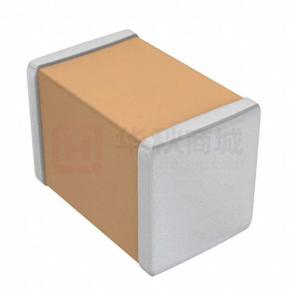
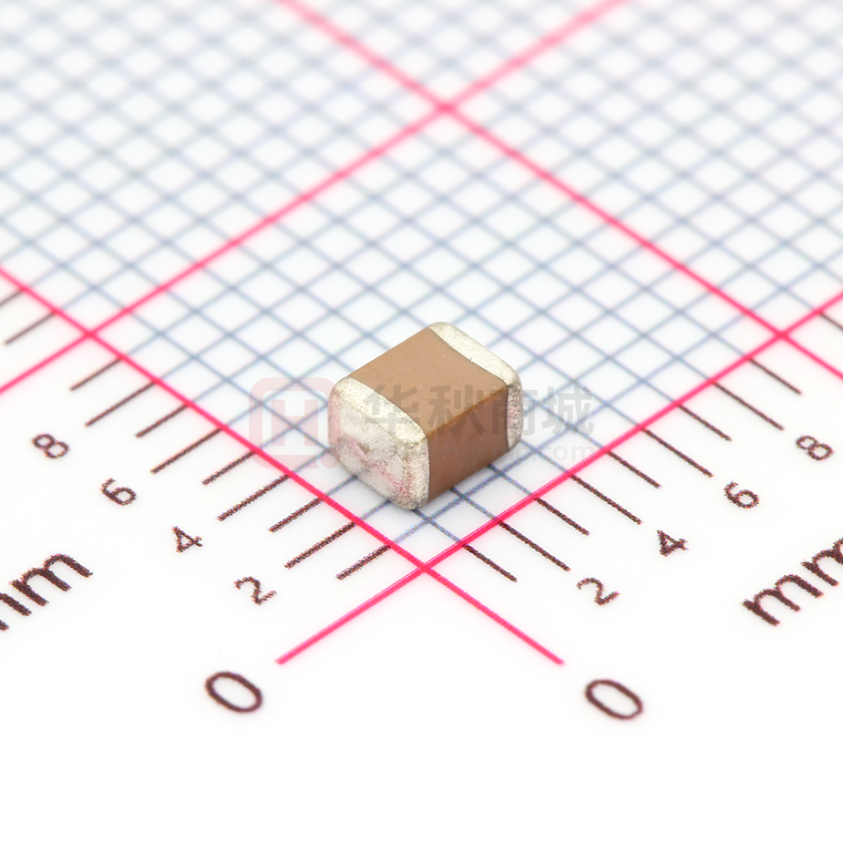


 工商网监
湘ICP备2023018690号
工商网监
湘ICP备2023018690号
