1-1-4 Linear Regulator ICs
SI-3000LSA Series
■Features
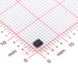
• Compact surface-mount package (SOP8) • Output current: 1 A
Surface-Mount, Low Current Consumption, Low Dropout Voltage
■Absolute Maximum Ratings
Parameter DC Input Voltage Output control terminal voltage DC Output Current Power Dissipation Junction Temperature Operating Ambient Temperature Storage Temperature Thermal Resistance (Junction to Lead (pin 8)) Thermal Resistance (Junction to Ambient Air) Symbol VIN VC IO PD1*1 PD2*2 Tj*3 Top Tstg Ratings 16 VIN 1 1.16 1.1 –30 to +150 –30 to +150 –30 to +150 36 100 Unit V V A W W °C °C °C °C/W °C/W (Ta=25°C)
• Low circuit current at output OFF: Iq(OFF) ≤ 1 µA (VC = 0 V) • Low dropout voltage: VDIF≤0.8 V (at IO = 1 A) VDIF ≤1.2 V (IO = 1 A) for SI-3018LSA • 4 types of output voltages (1.8 V, 2.5 V, 3.3 V, 5.0 V) available • Output ON/OFF control terminal voltage compatible with LS-TTL • Built-in foldback-type-overcurrent and thermal protection circuits
θ j-L θ j-a *2
*1: When mounted on glass-epoxy board 56.5 × 56.5 mm (copper laminate area 100%). *2: When mounted on glass-epoxy board 40 × 40 mm (copper laminate area 100%). *3: Thermal protection circuits may be activated if the junction temperature exceeds 135°C.
■Applications
• Auxiliary power supplies for PC • Battery-driven electronic equipment
■Recommended Operating Conditions
Ratings Parameter DC Input Voltage Range DC Output Current Range Operating Junction Temperature Operating Ambient Temperature Symbol VIN IO Tjop Taop SI-3018LSA 3.1 to 3.5*1 SI-3025LSA
*2
SI-3033LSA
*2
SI-3050LSA
*2
Unit V A °C °C
to 3.5*1 0 to 1
to 5.2*1
to 8.0
–20 to +125 –30 to +85
*1: VIN (max) and IO (max) are restricted by the relation PD = (VIN – VO) × IO. Please calculate these values referring to the reference data on page 69. *2: Refer to the Dropout Voltage parameter.
■Electrical Characteristics
Ratings Parameter Symbol min. Output Voltage VO Conditions VDIF Dropout Voltage Conditions Conditions Line Regulation Load Regulation Temperature Coefficient of Output Voltage Ripple Rejection Quiescent Circuit Current Circuit Current at Output OFF Overcurrent Protection Starting Current*1,3 Control Voltage (Output VC Terminal ON)*2 Control Voltage (Output OFF)*2 Control Current (Output ON) Control Current (Output OFF) ∆VLINE Conditions ∆VOLOAD Conditions ∆VO/∆Ta Conditions RREJ Conditions Iq Conditions Iq(OFF) Conditions IS1 Conditions VC, IH VC, IL IC, IH Conditions IC, IL Conditions 0 –5 0 –5 VC=0V 40 2.0 0.8 80 40 1.2 VIN=3.3V 2.0 0.8 80 VC=2V 0 –5 40 2 10 ± 0.3 VIN=3.3V, IO=5mA, Tj=0 to 100°C 60 VIN=3.3V, f=100 to 120HZ 1.7 VIN=3.3V, IO=0A 1 VIN=3.3V, IO=0A, VC=0V 1.2 VIN=3.3V 2.0 0.8 80 2.5 10 20 2 10 ± 0.3 VIN=3.3V, IO=5mA, Tj=0 to 100°C 57 VIN=3.3V, f=100 to 120HZ 1.7 VIN=3.3V, IO=0A 1 VIN=3.3V, IO=0A, VC=0V 1.2 VIN=5V 2.5 10 20 VIN=3.1 to 3.5V, IO=0.3A VIN=3.3V, IO=0 to 1A VIN=3.1 to 3.5V, IO=0.3A VIN=3.3V, IO=0 to 1A 1.764 SI-3018LSA typ. 1.800 – – 0.6 1.2 IO≤0.5A 0.8 IO≤1A 3 10 ± 0.3 VIN=5V, IO=5mA, Tj=0 to 100°C 55 VIN=5V, f=100 to 120HZ 1.7 VIN=5V, IO=0A 1 VIN=5V, IO=0A, VC=0V 2.5 10 20 max. 1.836 min. 2.450 SI-3025LSA typ. 2.500 max. 2.550 0.4 IO≤0.5A 0.8 min. 3.234 SI-3033LSA typ. 3.300 max. 3.366 0.4
(Ta=25°C, VC=2V, unless otherwise specified) SI-3050LSA min. 4.90 typ. 5.00 VIN=6V, IO=0.5A 0.4 IO≤0.5A 0.8 3 10 ± 0.5 VIN=6V, IO=5mA, Tj=0 to 100°C 55 VIN=6V, f=100 to 120HZ 1.7 VIN=6V, IO=0A 1 VIN=6V, IO=0A, VC=0V 1.2 VIN=6V 2.0 0.8 40 0 80 –5 2.5 15 30 V max. 5.10 V Unit
VIN=3.3V, IO=0.5A
VIN=3.3V, IO=0.5A
VIN=5V, IO=0.5A
VIN=4.5 to 5.5V, IO=0.3A VIN=5V, IO=0 to 1A
VIN=6 to 7V, IO=0.3A VIN=6V, IO=0 to 1A
mV mV mV/ °C dB mA
µA
A V
µA µA
*1: Is1 is specified at the 5% drop point of output voltage VO on the condition that VIN = 3.3 V (5 V for SI-3033LSA), and IO = 0.5 A. *2: Output is OFF when the output control terminal VC is open. Each input level is equivalent to LS-TTL level. Therefore, the device can be driven directly by LS-TTLs. *3: These products cannot be used in the following applications. Because these applications require a certain current at start-up and so the built-in foldback-type overcurrent protection may cause errors during start-up stage. (1) Constant current load (2) Positive and negative power supply (3) Series-connected power supply (4) VO adjustment by raising ground voltage
68
ICs
�SI-3000LSA Series
■External Dimensions (SOP8)
5.1±0.4 1.27 0.4±0.1 0.15+0.1 –0.05
0.5±0.1
(Unit : mm)
8
7
6
5
1
2
3
4
0.995max.
1.55±0.15 1.5±0.1
0
to
10 °
1.27
Pin Assignment q VIN w NC (Leave open) e VIN r VC t GND y GND u VO i VO Plastic Mold Package Type Flammability: UL94V-0 Product Mass: Approx. 0.1g
0.10 0.4±0.1 0.12 M
■Block Diagram
VIN 1 8 VO
0.05±0.05
4.4±0.2
NC 2
+ –
7 VO
VIN 3
TSD
6
6.2±0.3
GND
VC 4
5
GND
■Typical Connection Diagram
VIN CIN 1 2 3 4 VIN GND VC CO 8 7 6 5 VO
■Reference Data
PCB Copper Laminate Area vs. Junction to Ambient Air Thermal Resistance Allowable Output Current (vs. VIN-VOUT Voltage Difference) VIN-IO max
1.2
150 140 130
PCB (glass-epoxy, 40×40mm) 160mm (40×40) mm
1.0
Load
+
+
CO: Output capacitor (22 µF or larger) CIN: Input capacitor (10 µF) This capacitor is required in the case of an inductive input line or long wiring. Tantalum capacitors are recommended for CIN and CO, particularly at low temperatures. * Leave pin 2 open.
Tj = 120°C (20% derating of 150°C)
0.8
Iout (max) (A)
θ j-a (°C/W)
120 110 100 90
θ j-a=100°C/W
0.6
The inner frame stage, on which the PTr is mounted, is directly connected to the VOUT pin. Therefore, enlarging the copper laminate area around the VOUT pin is really effective for a heat radiation.
0.4
Ta=25°C Ta=85°C
0.2 80 70 100 0 1000 5000 1 2
3
4
Copper Laminate Area (mm2)
VIN-VOUT Voltage Difference (V)
ICs
69
�