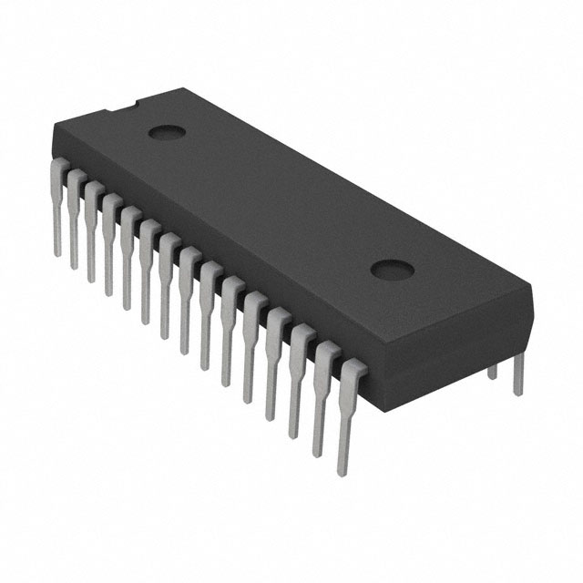
1-2-2 5-Phase Stepper Motor Driver ICs
SI-7510 New Pentagon Connection
■Absolute Maximum Ratings
Symbol
Ratings
Unit
Main Supply Voltage
Parameter
VCC1
44
V
Logic Supply Voltage
VCC2
7
V
VIN
–0.3 to VCC2
V
Logic Input Voltage
REF Input Voltage
SENCE Input Voltage
Charge Pump Output Voltage
VREF
–0.3 to VCC2
V
VSENCE
2
V
VMC3
48
V
PD
1.6
W
Operating Ambient Temperature
Ta
–10 to 80
°C
Storage Temperature
Tstg
–20 to 150
°C
Junction Temperature
Tj
150
°C
Symbol
Operating Ranges
Main Supply Voltage
VCC1
10 to 42*
Logic Supply Voltage
VCC2
3 to 5.5
REF Input Voltage
VREF
0.1 to 1
es
ig
■Recommended Operating Ranges
Parameter
ICC2
IIL
–20
IIH
–20
ENA Input Current
IENA
–100
REF Input Current
IREF
–20
SENCE Voltage
VSENCE
SENCE Current
ISENCE
VMOH
VMC3
High Side Output Voltage
VHGSL
(between gate sources)
VHGSH
CW/CCW, F/H
N
Input Data Setup Time
Input Data Hold Time
104
ICs
TCON
mA
1.25
V
20
µA
VIL=0V
20
µA
VIH=5.5V
20
µA
VENA=0V
20
µA
VREF=0 to 5.5V
V
VREF=1V
20
µA
VSENCE=0V, 2V
1
V
IMOL=1mA
V
IMOH=–1mA
V
V
1.5
V
300
µA
VCC1+9
V
1
100
VRC=0V
Without Zener diode
V
1
7.5
V
V
V
KHz
1
µs
PTW
1.5
µs
TIO
2
µs
ot
CW/CCW, F/H
fck
R
Maximum CL Frequency
mA
8.5
VLGH
Conditions
10
0.5
VLGL
Low Side Output Voltage
Maximum Input CL Width (on)
m
Charge Pump Output Voltage
ec
o
IRC
m
VRCH
RC Pin Outflow Current
Unit
25
4
VRCL
RC Pin Threshold Voltage
Output Delay Time
–20
VMOL
MO Output Voltage
V
V
max.
1
en
Logic Input Current
d
3.75
de
VIH
fo
VIL
Logic Input Voltage
Power-on Reset time
typ.
rN
min.
ICC1
V
(Ta=25°C, Vcc1=24V, VCC2=5V, unless otherwise specified)
Ratings
Symbol
Logic Supply Current
ew
■Electrical Characteristics
Main Supply Current
Unit
D
*: Insert a 5V Zener diode between VCC1 and VMC3 when using with VCC1 of 35 V or more.
Parameter
Except when tw
很抱歉,暂时无法提供与“SI-7510”相匹配的价格&库存,您可以联系我们找货
免费人工找货