Ordering number : EN*A1147
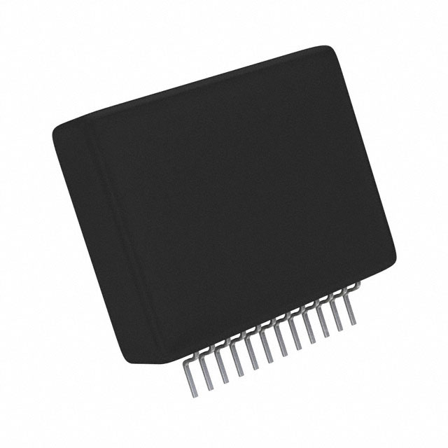
STK672-530
Thick-Film Hybrid IC
2-phase Stepping Motor Driver
Overview
The STK672-530 is a hybrid IC for use as a unipolar, 2-phase stepping motor driver with PWM current control.
Applications
• Office photocopiers, printers, etc.
Features
• The motor speed can be controlled by the frequency of an external clock signal.
• 2-phase excitation or 1-2 phase excitation is selected according to switching the state of the MODE pin (low or high).
• The phase is maintained even if the excitation mode is switched in the middle of operation.
• The direction of rotation can be changed by applying a high or low signal to the CWB pin used to select the direction of
rotation.
• Supports schmitt input for 2.5V high level input.
• Incorporating a current detection resistor (0.165Ω: resistor tolerance ±2%), motor current can be set using two external
resistors.
• Equipped with an ENABLE pin that, during clock input, allows motor output to be cut-off and resumed later while
maintaining the same excitation timing.
Any and all SANYO Semiconductor Co.,Ltd. products described or contained herein are, with regard to
"standard application", intended for the use as general electronics equipment (home appliances, AV equipment,
communication device, office equipment, industrial equipment etc.). The products mentioned herein shall not be
intended for use for any "special application" (medical equipment whose purpose is to sustain life, aerospace
instrument, nuclear control device, burning appliances, transportation machine, traffic signal system, safety
equipment etc.) that shall require extremely high level of reliability and can directly threaten human lives in case
of failure or malfunction of the product or may cause harm to human bodies, nor shall they grant any guarantee
thereof. If you should intend to use our products for applications outside the standard applications of our
customer who is considering such use and/or outside the scope of our intended standard applications, please
consult with us prior to the intended use. If there is no consultation or inquiry before the intended use, our
customer shall be solely responsible for the use.
Specifications of any and all SANYO Semiconductor Co.,Ltd. products described or contained herein stipulate
the performance, characteristics, and functions of the described products in the independent state, and are not
guarantees of the performance, characteristics, and functions of the described products as mounted in the
customer' s products or equipment. To verify symptoms and states that cannot be evaluated in an independent
device, the customer should always evaluate and test devices mounted in the customer' s products or
equipment.
71608HKIM No. A1147-1/22
�STK672-530
Specifications
Absolute Maximum Ratings at Tc = 25°C
Parameter
Symbol
Conditions
Ratings
unit
Maximum supply voltage 1
VCC max
No signal
52
V
Maximum supply voltage 2
VDD max
No signal
-0.3 to +7.0
V
Input voltage
VIN max
Logic input pins
-0.3 to +7.0
V
Output current 1
IOP max
10μA 1 pulse (resistance load)
5
A
Output current 2
IOH max
VDD=5V, CLOCK≥200Hz
2.65
A
Allowable power dissipation
Pd max
With an arbitrarily large heat sink. Per MOSFET
10.2
W
Operating substrate temperature
Tc max
105
°C
Junction temperature
Tj max
150
°C
Storage temperature
Tstg
-40 to +125
°C
Allowable Operating Ranges at Ta = 25°C
Parameter
Symbol
Conditions
Operating supply voltage 1
VCC
With signals applied
Operating supply voltage 2
VDD
Input high voltage
Ratings
unit
10 to 42
V
With signals applied
5±5%
V
VIH
Pins 8, 9, 10, 11, 12
2.5 to VDD
V
Input low voltage
VIL
Pins 8, 9, 10, 11, 12
0 to 0.6
V
Output current 1
IOH1
2.0
A
2.2
A
Tc=105°C, CLOCK≥200Hz,
Continuous operation, duty=100%
Output current 2
IOH2
Tc=80°C, CLOCK≥200Hz,
Continuous operation, duty=100%,
See the motor current (IOH) derating curve
CLOCK frequency
Phase driver withstand voltage
Recommended operating
fCL
VDSS
Tc
Minimum pulse width: at least 10μs
0 to 50
kHz
ID=1mA (Tc=25°C)
100min
V
0 to 105
°C
0.14 to 1.62
V
No condensation
substrate temperature
Recommended Vref range
Vref
Tc=105°C
Refer to the graph for each conduction-period tolerance range for the output current and brake current.
Electrical Characteristics at Tc = 25°C, VCC = 24V, VDD = 5.0V
Parameter
Symbol
Conditions
VDD supply current
ICCO
Pin 6 current CLOCK=GND
Output average current
Ioave
R/L=3Ω/3.8mH in each phase
min
typ
0.324
max
unit
3.1
7
0.36
0.396
mA
A
FET diode forward voltage
Vdf
If=1A (RL=23Ω)
Output saturation voltage
Vsat
RL=23Ω
Input high voltage
VIH
Pins 8, 9, 10, 11, 12
Input low voltage
VIL
Pins 8, 9, 10, 11, 12
0.6
V
Input leak current
IIL
Pins 8, 9, 10, 11, 12=GND and 5V
±10
μA
Vref input bias current
IIB
Pin 7 =1.0V
204
216
μA
PWM frequency
fc
45
55
kHz
1.0
1.6
V
0.45
0.64
V
2.5
35
V
Notes: A fixed-voltage power supply must be used.
No. A1147-2/22
�STK672-530
Package Dimensions
unit:mm (typ)
4192
3.3
5.1
0.4
1
12
9.0
24.0
29.5
2.9
1.0
2.0
0.5
11 2=22
Derating Curve of Motor Current, IOH, vs. STK672-530 Operating Substrate Temperature, Tc
IOH - Tc
3.0
200Hz 2 phase excitation
2.5
Motor current, IOH - A
Hold mode
2.0
1.5
1.0
0.5
0
0
10
20
30
40
50
60
70
80
90
Operating Substrate Temperature, Tc- °C
100
110
ITF02562
Notes
• The current range given above represents conditions when output voltage is not in the avalanche state.
• If the output voltage is in the avalanche state, see the allowable avalanche energy for STK672-5** series hybrid ICs given
in a separate document.
• The operating substrate temperature, Tc, given above is measured while the motor is operating.
Because Tc varies depending on the ambient temperature, Ta, the value of IOH, and the continuous or intermittent
operation of IOH, always verify this value using an actual set.
No. A1147-3/22
�STK672-530
Block Diagram
VDD(5V)
MODE
A
AB
B
BB
5
4
3
2
6
VDD
Excitation
mode
selection
8
CLOCK
9
CWB
10
RESETB
11
ENABLE
12
F1
F2
F3
F4
FAO
Phase
excitation
signal
generator
FAB
FBO
FBB
Phase
advance
counter
R1
R2
AI
Chopper
circuit
BI
CI
1
GND
VSS
Vref
7
Sample Application Circuit
STK672-530
VDD(5V)
6
CLOCK
9
MODE
8
CWB
10
ENABLE
12
R04
C04 C05 C06 C07
2-phase stepping motor driver
A
5
AB
4
B
3
BB
2
RESETB
+
R01
Vref
GND
7
D1
+
R02
C02
10μF
C01
at least 100μF
C08
11
R03
VCC
24V
+
1
P.GND
C03
10μF
R02 is normally open.
No. A1147-4/22
�STK672-530
Precautions
[GND wiring]
• To reduce noise on the 5V system, be sure to place the GND of C01 in the circuit given above as close as possible to
Pin 1 of the hybrid IC. Also, the GND side of RO2 must be directly wired from P.GND terminal Pin 1 in order to
accurately set the current.
[Input pins]
• Insert resistor RO3 (47 to 100Ω) so that the discharge energy from capacitor CO2 is not directly applied to the CMOS
IC in this hybrid device. If the diode D1 has Vf characteristics with Vf less than or equal to 0.6V (when If = 0.1A),
this will be smaller than the CMOS IC input pin diode Vf. If this is the case RO3 may be replaced with a short without
problem.
• Apply 2.5V High level input to pins 8, 9, 10, 11, and 12.
• If VDD is being applied, use care that each input pin does not apply a negative voltage less than -0.3V to P.GND,
Pin 1, and do not apply a voltage greater than or equal to VDD voltage.
• Since the input pins do not have built-in pull-up resistors, when the open-collector type pins 8, 9, 10, 11, and 12 are
used as inputs, a 10 to 47kΩ pull-up resistor (to VDD) must be used.
At this time, use a device for the open collector driver that has output current specifications that pull the voltage down
to less than 0.6V at Low level.
• To prevent malfunction due to chopping noise, we recommend that you mount a 1000pF capacitor between Pin 1 and
each of the input Pins 8, 9, 10, 11, and 12. Be sure to mount the capacitor as close as possible to the pins of hybrid IC.
If input is fixed Low, directly connect to Pin 1.
If input is fixed High, directly connect to the 5V power line.
[Current setting Vref]
• In consideration of the specifications of the Vref input bias current, IIB, a resistance from several kΩ to 100kΩ is
recommended for RO1.
• If the motor current is temporarily reduced, the circuit given below (STK672-530: IOH>0.17A) is recommended.
• Although the driver is equipped with a fixed current control function, it is not equipped with an overcurrent protection
function to ensure that the current does not exceed the maximum output current, IOH max. If Vref is mistakenly set to
a voltage that exceeds IOH max, the driver will be damaged by overcurrent.
5V
5V
RO1
RO1
Vref
Vref
R3
RO2
R3
RO2
No. A1147-5/22
�STK672-530
• Motor current peak value IOH setting
IOH
0
• When RO2 is open
IOH= [Vref×1k/(1k+3.9k)] ÷Rs= (Vref÷4.9) ÷Rs
The values 1k and 3.9k represent internal driver resistance values, while Rs represents the internal driver current
detection resistance.
Vref= (4.9k÷ (4.9k+RO1)) ×5V (or 3.3V) =IOH×4.9×Rs
The value 4.9k represents the series resistance value of the internal driver values of 1k and 3.9k.
• If RO2 is connected
IOH= [Vref×1k/ (1k+3.9k)] ÷Rs= (Vref÷4.9) ÷Rs
The values 1k and 3.9k represent the internal driver resistance values, while Rs represents the internal driver current
detection resistance.
Vref= (R0x÷ (RO1+R0x)) ×5V (or 3.3V) =IOH×4.9×Rs
= [(4.9k×RO2) ÷ ((4.9k×RO2) +RO1× (4.9k+RO2))] ×5V(or 3.3V)
R0x= (4.9k×RO2) ÷ (4.9k+RO2)
Rs represents the current detection resistance inside the HIC, while the value 4.9k in the formula above represents the
internal resistance value of the Vref pin.
Rs=0.165Ω when using the STK672-530
Rs=0.11Ω when using the STK672-540
[Smoke Emission Precuations]
If any of the output pins 2, 3, 4, and 5 is held open, the electrical stress onto the driver due to the inductive energy
accumulated in the motor could cause short-circuit followed by permanent damage to the internal MOSFET. As a result,
the STK672-530 may give rise to emit smoke.
Input Pin Functions
Pin Name
Pin No.
Function
Input Conditions When Operating
CLOCK
9
Reference clock for motor phase current switching
Operates on the rising edge of the signal
MODE
8
Excitation mode selection
Low: 2-phase excitation
CWB
10
Motor direction switching
Low: CW (forward)
RESETB
11
System reset and A, AB, B, and BB outputs cutoff.
High: 1-2 phase excitation
High: CCW (reverse)
A reset is applied by a low level
Applications must apply a reset signal for at least 10μs
when VDD is first applied.
ENABLE
12
The A, AB, B, and BB outputs are turned off, and after
The A, AB, B, and BB outputs are turned off by a low-
operation is restored by returning the ENABLE pin to the
level input.
high level, operation continues with the same excitation
timing as before the low-level input.
(1) A simple reset function is formed from D1, CO2, RO3, and RO4 in this application circuit. With the CLOCK input
held low, when the 5V supply voltage is brought up a reset is applied if the motor output phases A and BB are
driven. If the 5V supply voltage rise time is slow (over 50ms), the motor output phases A and BB may not be driven.
Increase the value of the capacitor CO2 and check circuit operation again.
(2) See the timing chart for the concrete details on circuit operation.
No. A1147-6/22
�STK672-530
Timing Charts
2-phase excitation
VDD
RESETB
MODE
CWB
CLOCK
ENABLE
FAO
FAB
FBO
FBB
1-2 phase excitation
VDD
RESETB
MODE
CWB
CLOCK
ENABLE
FAO
FAB
FBO
FBB
No. A1147-7/22
�STK672-530
1-2 phase excitation
VDD
RESETB
MODE
CWB
CLOCK
ENABLE
FAO
FAB
FBO
FBB
2-phase excitation→Switch to 1-2 phase excitation
VDD
RESETB
MODE
CWB
CLOCK
ENABLE
FAO
FAB
FBO
FBB
No. A1147-8/22
�STK672-530
1-2-phase excitation→Switch to 2 phase excitation
VDD
RESETB
MODE
CWB
CLOCK
ENABLE
FAO
FAB
FBO
FBB
No. A1147-9/22
�STK672-530
1-2 phase excitation (ENABLE)
VDD
RESETB
MODE
CWB
CLOCK
ENABLE
FAO
FAB
FBO
FBB
1-2 phase excitation (Hold operation results during fixed CLOCK)
VDD
RESETB
MODE
CWB
CLOCK
ENABLE
Hold operation
FAO
FAB
FBO
FBB
No. A1147-10/22
�STK672-530
Usage Notes
1. STK672-530 and STK672-540 input signal functions and timing
(All inputs have no internal pull-up resistor.)
[RESETB and CLOCK (Input signal timing when power is first applied)]
As shown in the timing chart, a RESETB signal input is required by the driver to operate with the timing in which the
F1 gate is turned on first. The RESETB signal timing must be set up to have a width of at least 10μs, as shown below.
The capacitor CO2, and the resistors RO3 and RO4 in the application circuit form simple reset circuit that uses the
RC time constant rising time. However, when designing the RESETB input based on VIH levels, the application
must have the timing shown in figure.
Rise of the 5V supply
voltage
RESETB signal input
At least 10μs
CLOCK signal
At least 5μs
Figure 1 RESETB and CLOCK Signals Input Timing
[CLOCK (Phase switching clock)]
• Input frequency: DC to 50kHz
• Minimum pulse width: 10μs
• Signals are read on the rising edge.
[CWB (Motor direction setting)]
The direction of rotation is switched by setting CWB to 1 (high) or 0 (low).
See the timing charts for details on the operation of the outputs.
Note: The state of the CWB input must not be changed during the 6.25μs period before and after the rising edge of
the CLOCK input.
[ENABLE (Controls forced OFF for A, AB, B, and selects BB and selects operation/hold mode of the hybrid IC)]
ENABLE=1: Normal operation
ENABLE=0: Outputs A, AB, B, and BB forced to the off state.
If, during the state where CLOCK signal input is provided, the ENABLE pin is set to 0 and then is later
restored to the 1 state, the IC will resume operation with the excitation timing continued from before
the point ENABLE was set to 0.
Enable must be initially set high for input as shown in the timing chart.
[MODE (Excitation mode selection)]
MODE=0: 2-phase excitation
MODE=1: 1-2 phase excitation
See the timing charts for details on output operation in these modes.
Note: The state of the MODE input must not be changed during the 5μs period before and after the rising edge of the
CLOCK input.
No. A1147-11/22
�STK672-530
[Configuration of Each Input Pin]
Input pins: Pin 8, 9, 10, 11, and 12
Control IC
5V
VSS
All input pins of this driver support schmitt input. Typ specifications at Tc = 25°C are given below. Hysteresis voltage
is 0.6V (VIHa-VILa).
When rising
When falling
1.7Vtyp
1.1Vtyp
Input voltage
VILa
VIHa
Input voltage specifications are as follows.
VIH=2.5V min
VIL=0.6V max
Input pin: Pin 7
5V
Vref
3.9kΩ/1%
7
R1 or R2/2%
0.1μF
GND
1
1kΩ/1%
No. A1147-12/22
�STK672-530
Because the ringing voltage VIG of the GND line is added to the input signals inside the hybrid IC, the greater the
through rate of input signals, the more opportunities there are to input a ringing signal at the rising or falling edge.
Particularly in cases where a capacitor is added to output pins 2, 3, 4, and 5 as shown in the figure below to suppress
electromagnetic noise, the ringing voltage increases even further due to charge/discharge of the capacitor. The ringing
voltage amplitude of this type may exceed 0.6V input Hysteresis voltage. Because the ringing signal can cause a
malfunction leading to failure due to over-current, be sure to apply input signals with the highest through rate possible.
Direct input with HC type CMOS ICs is recommended.
2-phase
stepping motor
driver
2200pF
A
AB
B
BB
VDD(5V)
MODE
24V
CLOCK
CWB
RESETB
ENABLE
GND
GND
1000pF
VIN
VSS
VIG
Vref
VIN
No. A1147-13/22
�STK672-530
2. Calculating STK672-530 HIC Internal Power Loss
The average internal power loss in each excitation mode of the STK672-530 can be calculated from the following
formulas.
Each excitation mode
2-phase excitation mode
2PdAVex= (Vsat+Vdf) ×0.5×CLOCK×IOH×t2+0.5×CLOCK×IOH× (Vsat×t1+Vdf×t3)
1-2 phase excitation mode
1-2PdAVex= (Vsat+Vdf) ×0.25×CLOCK×IOH×t2+0.25×CLOCK×IOH× (Vsat×t1+Vdf×t3)
Motor hold mode
HoldPdAVex= (Vsat+Vdf) ×IOH
Vsat: Combined voltage represented by the Ron voltage drop+shunt resistor
Vdf: Combined voltage represented by the MOSFET body diode+shunt resistor
CLOCK: Input CLOCK (CLOCK pin signal frequency)
t1, t2, and t3 represent the waveforms shown in the figure below.
t1: Time required for the winding current to reach the set current (IOH)
t2: Time in the constant current control (PWM) region
t3: Time from end of phase input signal until inverse current regeneration is complete
IOH
0A
t1
t2
t3
Motor COM Current Waveform Model
t1= (-L/(R+0.45)) In (1-((R+0.45)/VCC) ×IOH)
t3= (-L/R) In ((VCC+0.45)/(IOH×R+VCC+0.45))
VCC: Motor supply voltage (V)
L: Motor inductance (H)
R: Motor winding resistance (Ω)
IOH: Motor set output current crest value (A)
Relationship of CLOCK, t1, t2, and t3 in each excitation mode
2-phase excitation mode: t2= (2/CLOCK) - (t1+t3)
1-2 phase excitation mode: t2= (3/CLOCK) -t1
For Vsat and Vdf, be sure to substitute values from the graphs of Vsat vs. IOH and Vdf vs. IOH while the set current
value is IOH.
Then, determine whether a heat sink is required by comparing with the graph of ΔTc vs. Pd based on the average HIC
power loss calculated.
When designing a heat sink, refer to the section “Thermal design” found on the next page. The average HIC power
loss, PdAV, described above does not have the avalanche’s loss. To include the avalanche’s loss, be sure to add
Equation (2), “STK672-5** Allowable Avalanche Energy Value” to PdAV above. When using this IC without a fin
always check for temperature increases in the set, because the HIC substrate temperature, Tc, varies due to effects of
convection around the HIC.
No. A1147-14/22
�STK672-530
STK672-530 Output saturation voltage, Vsat - Output current, IOH
Vsat - IOH
1.4
1.2
°C
1.0
10
5
Output saturation voltage, Vsat - V
1.6
0.8
°C
25
0.6
0.4
0.2
0
0
0.5
1.0
1.5
2.0
2.5
Output current, IOH - A
3.0
ITF02563
STK672-530 Forward voltage, Vdf -Output current, IOH
Vdf- IOH
1.4
Forward voltage, Vdf - V
1.2
25°
C
1.0
°C
105
0.8
0.6
0.4
0.2
0
0
0.5
1.0
1.5
2.0
2.5
Output current, IOH - A
3.0
ITF02550
Substrate temperature rise , ΔTc (no heat sink) - Internal average power dissipation, PdAV
ΔTc - PdAV
Substrate temperature rise, ΔTc - °C
80
70
60
50
40
30
20
10
0
0
0.5
1.0
1.5
2.0
2.5
Hybrid IC internal average power dissipation, PdAV - W
3.0
ITF02566
No. A1147-15/22
�STK672-530
3. STK672-530 Allowable Avalanche Energy Value
(1) Allowable Range in Avalanche Mode
When driving a 2-phase stepping motor with constant current chopping using an STK672-5** Series hybrid IC,
the waveforms shown in Figure 1 below result for the output current, ID, and voltage, VDS.
VDSS: Voltage during avalanche operations
VDS
IOH: Motor current peak value
IAVL: Current during avalanche operations
ID
tAVL: Time of avalanche operations
ITF02557
Figure 1 Output Current, ID, and Voltage, VDS, Waveforms 1 of the STK672-5** Series when
Driving a 2-Phase Stepping Motor with Constant Current Chopping
When operations of the MOSFET built into STK672-5** Series ICs is turned off for constant current chopping,
the ID signal falls like the waveform shown in the figure above. At this time, the output voltage, VDS, suddenly
rises due to electromagnetic induction generated by the motor coil.
In the case of voltage that rises suddenly, voltage is restricted by the MOSFET VDSS. Voltage restriction by
VDSS results in a MOSFET avalanche. During avalanche operations, ID flows and the instantaneous energy at
this time, EAVL1, is represented by Equation (1).
EAVL1=VDSS×IAVL×0.5×tAVL ------------------------------------------- (1)
VDSS: V units, IAVL: A units, tAVL: sec units
The coefficient 0.5 in Equation (1) is a constant required to convert the IAVL triangle wave to a
square wave.
During STK672-5** Series operations, the waveforms in the figure above repeat due to the constant current
chopping operation. The allowable avalanche energy, EAVL, is therefore represented by Equation (2) used to find
the average power loss, PAVL, during avalanche mode multiplied by the chopping frequency in Equation (1).
PAVL=VDSS×IAVL×0.5×tAVL×fc ------------------------------------------- (2)
fc: Hz units (fc is set to the PWM frequency of 50kHz.)
For VDSS, IAVL, and tAVL, be sure to actually operate the STK672-5** Series and substitute values when
operations are observed using an oscilloscope.
Ex. If VDSS=110V, IAVL=1A, tAVL=0.2μs when using a STK672-530 driver, the result is:
PAVL=110×1×0.5×0.2×10-6×50×103=0.55W
VDSS=110V is a value actually measured using an oscilloscope.
The allowable loss range for the allowable avalanche energy value, PAVL, is shown in the graph in Figure 3.
When examining the avalanche energy, be sure to actually drive a motor and observe the ID, VDSS, and tAVL
waveforms during operation, and then check that the result of calculating Equation (2) falls within the allowable
range for avalanche operations.
No. A1147-16/22
�STK672-530
(2) ID and VDSS Operating Waveforms in Non-avalanche Mode
Although the waveforms during avalanche mode are given in Figure 1, sometimes an avalanche does not result during
actual operations.
Factors causing avalanche are listed below.
• Poor coupling of the motor’s phase coils (electromagnetic coupling of A phase and AB phase, B phase and
BB phase).
• Increase in the lead inductance of the harness caused by the circuit pattern of the P.C. board and motor.
• Increases in VDSS, tAVL, and IAVL in Figure 1 due to an increase in the supply voltage from 24V to 36V.
If the factors above are negligible, the waveforms shown in Figure 1 become waveforms without avalanche as
shown in Figure 2.
Under operations shown in Figure 2, avalanche does not occur and there is no need to consider the allowable loss
range of PAVL shown in Figure 3.
VDS
IOH: Motor current peak value
ID
ITF02558
Figure 2 Output Current, ID, and Voltage, VDS, Waveforms 2 of the STK672-5** Series when Driving a
2-Phase Stepping Motor with Constant Current Chopping
Average power loss in the avalanche state, PAVL- W
Figure 3 Allowable Loss Range, PAVL-IOH During STK672-530 Avalanche Operations
PAVL - IOH
7
6
80°C
5
4
105°C
3
2
1
0
0
0.5
1.0
1.5
Motor phase current, IOH - A
2.0
2.5
ITF02565
Note:
The operating conditions given above represent a loss when driving a 2-phase stepping motor with constant current
chopping.
Because it is possible to apply 3.7W or more at IOH=0A, be sure to avoid using the MOSFET body diode that is used
to drive the motor as a zener diode.
No. A1147-17/22
�STK672-530
4. Thermal design
[Operating range in which a heat sink is not used]
Use of a heat sink to lower the operating substrate temperature of the HIC (Hybrid IC) is effective in increasing the
quality of the HIC.
The size of heat sink for the HIC varies depending on the magnitude of the average power loss, PdAV, within the
HIC. The value of PdAV increases as the output current increases. To calculate PdAV, refer to “Calculating Internal
HIC Loss for the STK672-530” in the specification document.
Calculate the internal HIC loss, PdAV, assuming repeat operation such as shown in Figure 1 below, since conduction
during motor rotation and off time both exist during actual motor operations.
IO1
Motor phase current
(sink side)
IO2
0A
-IO1
T1
T2
T3
T0
Figure 1 Motor Current Timing
T1: Motor rotation operation time
T2: Motor hold operation time
T3: Motor current off time
T2 may be reduced, depending on the application.
T0: Single repeated motor operating cycle
IO1 and IO2: Motor current peak values
Due to the structure of motor windings, the phase current is a positive and negative current with a pulse form.
Note that figure 1 presents the concepts here, and that the on/off duty of the actual signals will differ.
The hybrid IC internal average power dissipation PdAV can be calculated from the following formula.
PdAV= (T1×P1+T2×P2+T3×0) ÷T0 ---------------------------- (I)
(Here, P1 is the PdAV for IO1 and P2 is the PdAV for IO2)
If the value calculated using Equation (I) is 1.5W or less, and the ambient temperature, Ta, is 60°C or less, there is no
need to attach a heat sink. Refer to Figure 2 for operating substrate temperature data when no heat sink is used.
[Operating range in which a heat sink is used]
Although a heat sink is attached to lower Tc if PdAV increases, the resulting size can be found using the value of
θc-a in Equation (II) below and the graph depicted in Figure 3.
θc-a= (Tc max-Ta) ÷PdAV ---------------------------- (II)
Tc max: Maximum operating substrate temperature =105°C
Ta: HIC ambient temperature
Although a heat sink can be designed based on equations (I) and (II) above, be sure to mount the HIC in a set and
confirm that the substrate temperature, Tc, is 105°C or less.
The average HIC power loss, PdAV, described above represents the power loss when there is no avalanche operation.
To add the loss during avalanche operations, be sure to add Equation (2), “Allowable STK672-5** Avalanche
Energy Value”, to PdAV.
No. A1147-18/22
�STK672-530
Figure 2 Substrate temperature rise, ΔTc - Internal average power dissipation, PdAV
ΔTc - PdAV
Substrate temperature rise, ΔTc - °C
80
70
60
50
40
30
20
10
0
0
0.5
1.0
1.5
2.0
2.5
Hybrid IC internal average power dissipation, PdAV - W
3.0
ITF02566
Figure 3 Heat sink area (Board thickness: 2mm) - θc-a
θc-a - S
Heat sink thermal resistance, θc-a - °C/W
100
7
5
3
2
Wi
10
Wit
ha
7
5
th n
flat
3
o su
rfac
e fi
blac
k su
nish
rfac
e fi
2
1.0
10
2
3
5
7
100
2
Heat sink area, S - cm2
nish
3
5
7 1000
ITF02554
No. A1147-19/22
�STK672-530
5. Changes in motor state when switching excitation with STK672-5** Series
Example 1: Switching from 2-phase to 1-2 phase excitation
Motor status is maintained when the excitation mode (MODE) is switched during motor rotation.
Because CLOCK cannot be detected when the interval between the rise in the MODE and CLOCK signals is 5μs or less,
the mode may not change for one CLOCK cycle.
MODE
FAO
FAB
FB0
FBB
CLOCK
(1)
(2)
(3)
(4)
(5)
(6)
(7)
A
B
B
A
The solid arrows indicate 2-phase excitation, and dashed arrows indicate 1-phase excitation.
No. A1147-20/22
�STK672-530
Example 2: Switching from 1-2 phase to 2-phase excitation
Motor status is maintained when the excitation mode (MODE) is switched during motor rotation.
Because CLOCK cannot be detected when the interval between the rise in the MODE signal and CLOCK signal is 5μs
or less, the mode may not change for one CLOCK cycle.
MODE
FAO
FAB
FB0
FBB
CLOCK
(1)
(2)
(3)
(4)
(5)
(6)
(7)
A
B
B
A
The solid arrows indicate 2-phase excitation, and dashed arrows indicate 1-phase excitation.
No. A1147-21/22
�STK672-530
SANYO Semiconductor Co.,Ltd. assumes no responsibility for equipment failures that result from using
products at values that exceed, even momentarily, rated values (such as maximum ratings, operating condition
ranges, or other parameters) listed in products specifications of any and all SANYO Semiconductor Co.,Ltd.
products described or contained herein.
SANYO Semiconductor Co.,Ltd. strives to supply high-quality high-reliability products, however, any and all
semiconductor products fail or malfunction with some probability. It is possible that these probabilistic failures or
malfunction could give rise to accidents or events that could endanger human lives, trouble that could give rise
to smoke or fire, or accidents that could cause damage to other property. When designing equipment, adopt
safety measures so that these kinds of accidents or events cannot occur. Such measures include but are not
limited to protective circuits and error prevention circuits for safe design, redundant design, and structural
design.
In the event that any or all SANYO Semiconductor Co.,Ltd. products described or contained herein are
controlled under any of applicable local export control laws and regulations, such products may require the
export license from the authorities concerned in accordance with the above law.
No part of this publication may be reproduced or transmitted in any form or by any means, electronic or
mechanical, including photocopying and recording, or any information storage or retrieval system, or otherwise,
without the prior written consent of SANYO Semiconductor Co.,Ltd.
Any and all information described or contained herein are subject to change without notice due to
product/technology improvement, etc. When designing equipment, refer to the "Delivery Specification" for the
SANYO Semiconductor Co.,Ltd. product that you intend to use.
Information (including circuit diagrams and circuit parameters) herein is for example only; it is not guaranteed
for volume production.
Upon using the technical information or products described herein, neither warranty nor license shall be granted
with regard to intellectual property rights or any other rights of SANYO Semiconductor Co.,Ltd. or any third
party. SANYO Semiconductor Co.,Ltd. shall not be liable for any claim or suits with regard to a third party's
intellectual property rights which has resulted from the use of the technical information and products mentioned
above.
This catalog provides information as of July, 2008. Specifications and information herein are subject
to change without notice.
PS No. A1147-22/22
�