TVS Diode Array For ESD and Latch-Up Protection
PROTECTION PRODUCTS Description
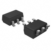
The SMS series of TVS arrays are designed to protect sensitive electronics from damage or latch-up due to ESD and other voltage-induced transient events. Each device will protect up to five lines. They are available with operating voltages of 5V, 12V, 15V and 24V. They are unidirectional devices and may be used on lines where the signal polarities are above ground. TVS diodes are solid-state devices designed specifically for transient suppression. They feature large crosssectional area junctions for conducting high transient currents. They offer desirable characteristics for board level protection including fast response time, low operating and clamping voltage and no device degradation. The SMS series devices may be used to meet the immunity requirements of IEC 61000-4-2, level 4. The low cost SOT23-6L package makes them ideal for use in portable electronics such as cell phones, PDA’s, and notebook computers.
SMS05C through SMS24C
Features
Transient protection for data lines to IEC 61000-4-2 (ESD) ±15kV (air), ±8kV (contact) IEC 61000-4-4 (EFT) 40A (5/50ns) IEC 61000-4-5 (Lightning) 24A (8/20µs) Small package for use in portable electronics Protects five I/O lines Working voltages: 5V, 12V, 15V and 24V Low leakage current Low operating and clamping voltages Solid-state silicon avalanche technology
Mechanical Characteristics
EIAJ SOT23-6L package Molding compound flammability rating: UL 94V-0 Marking : Marking Code Packaging : Tape and Reel per EIA 481
Applications
Cell phone Handsets and Accessories Microprocessor Based Equipment Personal Digital Assistants (PDA’s) Notebooks, Desktops, and Servers Portable Instrumentation Set Top Box Peripherals MP3 Players Cordless Phones
Circuit Diagram
Schematic & PIN Configuration
SOT23-6L (Top View)
Revision 08/11/04 1 www.semtech.com
�SMS05C through SMS24C
PROTECTION PRODUCTS Absolute Maximum Rating
Rating Peak Pulse Power (tp = 8/20µs) Peak Forward Voltage (IF=1A, tp=8/20µs) Lead Soldering Temperature Operating Temperature Storage Temperature Symbol Pp k VFP TL TJ TSTG Value 300 1.5 260 (10 sec.) -55 to +125 -55 to +150 Units Watts V °C °C °C
Electrical Characteristics
SMS05C Par ame te r Reverse Stand-Off Voltage Reverse Breakdown Voltage Reverse Leakage Current Clamp ing Voltage Clamp ing Voltage Peak Pulse Current Junction Cap acitance Symbo l VRWM V BR IR VC VC IP P Cj It = 1mA VRWM = 5V, T=25°C IPP = 5A, tp = 8/20µ s IPP = 24A, tp = 8/20µ s tp = 8/20µ s Between I/O Pins and Ground VR = 0V, f = 1MHz 325 6 20 9.8 14.5 24 400 Co nditio ns Minimum Typical Maximum 5 Units V V µA V V A pF
SMS12C Par ame te r Reverse Stand-Off Voltage Reverse Breakdown Voltage Reverse Leakage Current Clamp ing Voltage Clamp ing Voltage Peak Pulse Current Junction Cap acitance Symbo l VRWM V BR IR VC VC IP P Cj It = 1mA VRWM = 12V, T=25°C IPP = 5A, tp = 8/20µ s IPP = 15A, tp = 8/20µ s tp = 8/20µ s Between I/O Pins and Ground VR = 0V, f = 1MHz 135 13.3 1 19 23 15 150 Co nditio ns Minimum Typical Maximum 12 Units V V µA V V A pF
2004 Semtech Corp.
2
www.semtech.com
�SMS05C through SMS24C
PROTECTION PRODUCTS Electrical Characteristics (Continued)
SMS15C Par ame te r Reverse Stand-Off Voltage Reverse Breakdown Voltage Reverse Leakage Current Clamp ing Voltage Clamp ing Voltage Peak Pulse Current Junction Cap acitance Symbo l VRWM V BR IR VC VC IP P Cj It = 1mA VRWM = 15V, T=25°C IPP = 5A, tp = 8/20µ s IPP = 12A, tp = 8/20µ s tp = 8/20µ s Between I/O Pins and Ground VR = 0V, f = 1MHz 100 16.7 1 24 29 12 125 Co nditio ns Minimum Typical Maximum 15 Units V V µA V V A pF
SMS24C Par ame te r Reverse Stand-Off Voltage Reverse Breakdown Voltage Reverse Leakage Current Clamp ing Voltage Clamp ing Voltage Peak Pulse Current Junction Cap acitance Symbo l VRWM V BR IR VC VC IP P Cj It = 1mA VRWM = 24V, T=25°C IPP = 5A, tp = 8/20µ s IPP = 8A, tp = 8/20µ s tp = 8/20µ s Between I/O Pins and Ground VR = 0V, f = 1MHz 60 26.7 1 40 44 8 75 Co nditio ns Minimum Typical Maximum 24 Units V V µA V V A pF
2004 Semtech Corp.
3
www.semtech.com
�SMS05C through SMS24C
PROTECTION PRODUCTS Typical Characteristics
Non-Repetitive Peak Pulse Power vs. Pulse Time
10 Peak Pulse Power - Ppk (kW)
Power Derating Curve
110 100 90 % of Rated Power or IPP 80 70 60 50 40 30 20 10
1
0.1
0.01 0.1 1 10 Pulse Duration - tp (µs) 100 1000
0 0 25 50 75 100
o
125
150
Ambient Temperature - TA ( C)
Pulse Waveform
110 100 90 80 Percent of IPP 70 60 50 40 30 20 10 0 0 5 10 15 T im e (µs) 20 25 30 td = I PP /2 e -t W aveform Parameters: tr = 8µs td = 20µs
Clamping Voltage vs. Peak Pulse Current
45 40 Clamping Voltage - VC (V) 35 30 25 20 15 10 5 0 0 5 10 15 20 25 30 Peak Pulse Current - IPP (A) SMS05C SMS15C SMS12C SMS24C Waveform Parameters: tr = 8µs td = 20µs
Forward Voltage vs. Forward Current
5 4.5 Forward Voltage - VF (V) 4 3.5 3 2.5 2 1.5 1 0.5 0 0 5 10 15 20 25 30 35 40 45 Forward Current - IF (A) Waveform Parameters: tr = 8µs td = 20µs
2004 Semtech Corp.
4
www.semtech.com
�SMS05C through SMS24C
PROTECTION PRODUCTS Applications Information
Device Connection for Protection of Five Data Lines The SMSxxC is designed to protect up to five unidirectional data lines. The device is connected as follows: 1. Unidirectional protection of five I/O lines is achieved by connecting pins 1, 3, 4, 5 and 6 to the data lines. Pin 2 is connected to ground. The ground connection should be made directly to the ground plane for best results. The path length is kept as short as possible to reduce the effects of parasitic inductance in the board traces. SMSxxC Circuit Diagram
Circuit Board Layout Recommendations for Suppression of ESD. Good circuit board layout is critical for the suppression of ESD induced transients. The following guidelines are recommended: Place the SMSxxC near the input terminals or connectors to restrict transient coupling. Minimize the path length between the SMSxxC and the protected line. Minimize all conductive loops including power and ground loops. The ESD transient return path to ground should be kept as short as possible. Never run critical signals near board edges. Use ground planes whenever possible.
Protection of Five Unidirectional Lines
2004 Semtech Corp.
5
www.semtech.com
�SMS05C through SMS24C
PROTECTION PRODUCTS Outline Drawing Outline Drawing - SO-8
A e1 N EI 1 ccc C 2X N/2 TIPS B 2 E D H GAGE PLANE 0.25 e DETAIL D aaa C A2 SEATING PLANE C A1 bxN bbb C A-B D A SEE DETAIL SIDE VIEW L (L1) H c
DIM
A A1 A2 b c D E1 E e e1 L L1 N 01 aaa bbb ccc
DIMENSIONS INCHES MILLIMETERS MIN NOM MAX MIN NOM MAX
.057 .035 .000 .006 .035 .045 .051 .010 .020 .003 .009 .110 .114 .118 .060 .063 .069 .110 BSC .037 BSC .075 BSC .012 .018 .024 (.024) 6 0° 10° .004 .008 .008 1.45 0.90 0.00 0.15 .90 1.15 1.30 0.25 0.50 0.08 0.22 2.80 2.90 3.00 1.50 1.60 1.75 2.80 BSC 0.95 BSC 1.90 BSC 0.30 0.45 0.60 (0.60) 6 0° 10° 0.10 0.20 0.20
2X E/2
01
A
A
NOTES: 1. CONTROLLING DIMENSIONS ARE IN MILLIMETERS (ANGLES IN DEGREES). 2. DATUMS -A- AND -B- TO BE DETERMINED AT DATUM PLANE -H3. DIMENSIONS "E1" AND "D" DO NOT INCLUDE MOLD FLASH, PROTRUSIONS OR GATE BURRS.
Land Pattern
X
DIM
(C) G Y Z C G P X Y Z
DIMENSIONS MILLIMETERS INCHES
(.098) .055 .037 .024 .043 .141 (2.50) 1.40 0.95 0.60 1.10 3.60
P
NOTES: 1. THIS LAND PATTERN IS FOR REFERENCE PURPOSES ONLY. CONSULT YOUR MANUFACTURING GROUP TO ENSURE YOUR COMPANY'S MANUFACTURING GUIDELINES ARE MET.
2004 Semtech Corp.
6
www.semtech.com
�SMS05C through SMS24C
PROTECTION PRODUCTS Marking Codes
Part Number SMS05C SMS12C SMS15C SMS24C Marking Code C05 C12 C15 C24
Note: Pin 1 Identified with a dot.
Ordering Information
Part Number SMS05C.TC SMS12C.TC SMS15C.TC SMS24C.TC SMS05C.TCT SMS12C.TCT SMS15C.TCT SMS24C.TCT Working Voltage SnPb SnPb SnPb SnPb Pb Free Pb Free Pb Free Pb Free Qty per Reel 3,000 3,000 3,000 3,000 3,000 3,000 3,000 3,000 R eel Size 7 Inch 7 Inch 7 Inch 7 Inch 7 Inch 7 Inch 7 Inch 7 Inch
Note: (1) No suffix indicates tube pack.
2004 Semtech Corp.
7
www.semtech.com
�
很抱歉,暂时无法提供与“SMS12C.TCT”相匹配的价格&库存,您可以联系我们找货
免费人工找货