Z-Power LED
X10490
Technical
Data
Sheet
Specification
[STW8Q14BE]
CUSTOMER
Checked by
Approved by
SUPPLIER
Drawn by
Approved by
Rev. 04
September. 2011
www.seoulsemicon.com
Document No. : SSC- QP- 7- 07- 24
�Z-Power LED
X10490
Technical
Data
Sheet
CONTENTS
1.
Description
2.
Absolute Maximum Ratings
3.
Electro-Optical Characteristics
4.
Optical characteristics
5.
Reliability Test
6.
Color & Binning
7.
Bin Code Description
8.
Outline Dimension
9.
Reel Structure
10. Packing
11. Soldering
12. Precaution for use
13. Handling of Silicone Resin LEDs
Rev. 04
September. 2011
www.seoulsemicon.com
Document No. : SSC- QP- 7- 07- 24
�Z-Power LED
X10490
Technical
Data
Sheet
STW8Q14BE
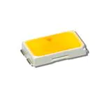
1. Description
This surface-mount LED comes in
standard package dimension. It has a
substrate made up of a molded plastic
reflector sitting on top of a bent lead
frame. The die is attached within the
reflector cavity and the cavity is
encapsulated by silicone.
Features
White colored SMT package.
•
The package design coupled with
careful selection of component
materials allow these products to
perform with high reliability.
Pb-free Reflow Soldering
Application
•
Suitable for all SMT
assembly methods ;
Suitable for all soldering
methods
•
RoHS Compliant
Applications
•
Interior lighting
•
General lighting
•
Indoor and out door
displays
•
Architectural / Decorative
lighting
Rev. 04
September. 2011
www.seoulsemicon.com
Document No. : SSC- QP- 7- 07- 24
�Z-Power LED
X10490
Technical
Data
Sheet
2. Absolute maximum ratings
Parameter
[1]
Symbol
Value
Unit
Power Dissipation
Pd
560
mW
Forward Current
IF
160
mA
Operating Temperature
Topr
-40~+85
Storage Temperature
Tstg
-40~+100
Junction Temperature
Tj
125
℃
℃
℃
[1] Care is to be taken that power dissipation does not exceed the absolute maximum rating of the product.
* LED’s properties might be different from suggested values like above and below tables if operation condition
will be exceeded our parameter range.
3. Electro-Optical characteristics
Parameter
Forward Voltage*
Reverse Voltage
Symbol
Condition
Min.
Typ.
Max.
Unit
VF
IF=100mA
2.9
3.2
3.5
V
VR
IR=5mA
-
0.9
1.2
V
Iv
IF=100mA
-
10.3
30.5
-
[1]
Luminous Intensity*
(2600~3700K)
Luminous Intensity*[1]
(3700~7000K)
Color Correlated Temperature
Viewing Angle
[2]
Color Rendering Index*
Iv
IF=100mA
-
CCT
IF=100mA
2,600
-
7,000
K
2Θ1/2
IF=100mA
-
120
-
deg.
Ra
IF=100mA
80
-
90
-
1.5k ;100pF
5
-
-
KV
IF=100mA
-
18
-
ºC/W
ESD (HBM)
Thermal resistance
[3]
cd
lm
10.8
32
RthJS
Ω
[1] The luminous intensity IV was measured at the peak of the spatial pattern which may not be aligned
with the mechanical axis of the LED package.
[2] 2Θ1/2 is the off-axis where the luminous intensity is 1/2 of the peak intensity.
[3] Thermal resistance: RthJS (Junction / solder)
* Tolerance : VF :± 0.1V, IV :± 10%, Ra :± 3, x,y :± 0.01
[Note] All measurements were made under the standardized environment of SSC.
Rev. 04
September. 2011
www.seoulsemicon.com
Document No. : SSC- QP- 7- 07- 24
�Z-Power LED
X10490
Technical
Data
Sheet
4. Optical characteristics
Forward Voltage
vs. Forward Current
Ta=25
Forward Current
vs. Relative Luminous Intensity
℃
Ta=25
℃
1.6
100
Relative Luminous Intensity
Forward Current IF [mA]
1.4
10
1.2
1.0
0.8
0.6
0.4
0.2
1
0.0
3.0
3.2
3.4 3.6 3.8 4.0 4.2
Forward Voltage VF [V]
4.4
0
4.6
20
40
60
80
100
120
140
160
Forward Current IF [mA]
Forward Current
vs. Chromaticity Coordinate
Directivity
Ta=25
℃
Ta=25
℃
0.368
0
-30
0.366
30
y
20mA
60mA
-60
100mA
0.364
60
150mA
200mA
0.362
-90
0.360
0.336
0.337
0.338
0.339
0.340
90
0.341
x
Rev. 04
September. 2011
www.seoulsemicon.com
Document No. : SSC- QP- 7- 07- 24
�Z-Power LED
X10490
Technical
Data
Sheet
Relative Light Output
vs. Junction Temperature
Forward Voltage Shift
vs. Junction Temperature
IF=100mA
1.0
1.0
0.8
0.8
Relative Light Output
Relative Forward Voltage
IF=100mA
0.6
0.4
0.6
0.4
0.2
0.2
0.0
0.0
30
45
60
75
90
105
120
O
30
45
60
75
90
105
120
O
Ju n ctio n te m p e ra tu re T j( C )
Junction tem perature Tj( C)
℃
Junction Temperature ( )
vs. Chromaticity Coordinate
IF=100mA
0.335
0.330
25
0.325
y
45
65
0.320
85
105
0.315
0.310
0.315
0.320
0.325
0.330
x
Rev. 04
September. 2011
www.seoulsemicon.com
Document No. : SSC- QP- 7- 07- 24
�Spectrum
Ta=25
200
160
Relative Emission Intensity
1.0
140
o
R th J-A = 1 0 0 C /W
120
100
80
60
℃, I =100mA
F
2600~3700K
3700~4700K
4700~7000K
180
Forward Current IF[mA]
Z-Power LED
X10490
Technical
Data
Sheet
Ambient Temperature
vs. Maximum Forward Current
0.5
40
20
0
-4 0
-2 0
0
20
40
60
80
O
100
0.0
300
400
500
600
700
800
Wavelength [nm]
A m b ie n t te m p e ra tu re T a ( C )
Rev. 04
September. 2011
www.seoulsemicon.com
Document No. : SSC- QP- 7- 07- 24
�Z-Power LED
X10490
Technical
Data
Sheet
5. Reliability Test
Item
Reference
Test Conditions
Duration
/ Cycle
Number
of
Damaged
Thermal Shock
EIAJ
ED-4701
Ta =-40oC(30min) ~
100oC(30min)
100 Cycle
0/22
High Temperature
Storage
EIAJ
ED-4701
Ta =100oC
1000 Hours
0/22
High Temp. High
Humidity Storage
EIAJ
ED-4701
Ta =60oC, RH=90%
1000 Hours
0/22
Low Temperature
Storage
EIAJ
ED-4701
Ta =-40oC
1000 Hours
0/22
Operating
Endurance Test
Internal
Reference
Ta =25oC, IF =100mA
1000 Hours
0/22
High Temperature
High Humidity Life
Test
Internal
Reference
Ta =60oC, RH=90%, IF =100mA
500 Hours
0/22
High Temperature
Life Test
Internal
Reference
Ta =85oC, IF =100mA
500 Hours
0/22
Low Temperature
Life Test
Internal
Reference
Ta =-40oC, IF =100mA
1000 Hours
0/22
ESD(HBM)
MIL-STD883D
5KV at 1.5k ; 100pF
3 Time
0/22
Reflow
Tsol
260 < 10sec. Reflow Soldering
℃
3 Time
0/22
Ω
□ CRITERIA FOR JUDGING THE DAMAGE
Criteria for Judgment
Item
Symbol
Condition
Forward Voltage
VF
Luminous Intensity
IV
MIN
MAX
IF =100mA
-
USL [1] × 1.2
IF =100mA
LSL [2] × 0.7
-
Note : [1] USL : Upper Standard Level
[2] LSL : Lower Standard Level
Rev. 04
September. 2011
www.seoulsemicon.com
Document No. : SSC- QP- 7- 07- 24
�Z-Power LED
X10490
Technical
Data
Sheet
6. Color & Binning
0.46
0.44
Energy Star Rank
2600K
2900K
2700K
3000K
3200K
0.42
G1
G0
3700K
0.40
E1
4500K
CIE Y
4700K
0.38
E2
D0
5300K
5600K
0.36
6000K
0.34
6500K
A1
7000K A0 A3
A2 A5
0.32
C1
C0
B1 C2
B0
B2
D3
H5
G5
G4
F5
E3
D1
5000K
H4
F3
F2
E0
G3
G2
F0
4200K
H3
H2
F1
4000K
H1
H0
3500K
F4
E5
E4
D2
D5
C3
D4
C5
B3 C4
B5
B4
A4
0.30
0.28
0.28
0.30
0.32
0.34
0.36
0.38
0.40
0.42
0.44
0.46
0.48
0.50
CIE X
Rev. 04
September. 2011
www.seoulsemicon.com
Document No. : SSC- QP- 7- 07- 24
�Z-Power LED
X10490
Technical
Data
Sheet
6. Color & Binning
● COLOR RANK
6500~7000K
A0
A2
A4
CIE X
CIE Y
CIE X
CIE Y
CIE X
CIE Y
0.3028
0.3304
0.3041
0.324
0.3055
0.3177
0.3041
0.324
0.3055
0.3177
0.3068
0.3113
0.3126
0.3324
0.3136
0.3256
0.3146
0.3187
0.3115
0.3393
0.3126
0.3324
0.3136
0.3256
6000~6500K
A1
A3
A5
CIE X
CIE Y
CIE X
CIE Y
CIE X
CIE Y
0.3115
0.3393
0.3126
0.3324
0.3136
0.3256
0.3126
0.3324
0.3136
0.3256
0.3146
0.3187
0.321
0.3408
0.3216
0.3334
0.3221
0.3261
0.3205
0.3481
0.321
0.3408
0.3216
0.3334
5600~6000K
B0
B2
B4
CIE X
CIE Y
CIE X
CIE Y
CIE X
CIE Y
0.3207
0.3462
0.3212
0.3389
0.3217
0.3316
0.3212
0.3389
0.3217
0.3316
0.3222
0.3243
0.3293
0.3461
0.3293
0.3384
0.3294
0.3306
0.3292
0.3539
0.3293
0.3461
0.3293
0.3384
5300~5600K
B1
B3
B5
CIE X
CIE Y
CIE X
CIE Y
CIE X
CIE Y
0.3292
0.3539
0.3293
0.3461
0.3293
0.3384
0.3293
0.3461
0.3293
0.3384
0.3294
0.3306
0.3373
0.3534
0.3369
0.3451
0.3366
0.3369
0.3376
0.3616
0.3373
0.3534
0.3369
0.3451
Rev. 04
* Measurement Uncertainty of the Color Coordinates : ± 0.01
September. 2011
www.seoulsemicon.com
Document No. : SSC- QP- 7- 07- 24
�Z-Power LED
X10490
Technical
Data
Sheet
6. Color & Binning
● COLOR RANK
5000~5300K
C0
C2
C4
CIE X
CIE Y
CIE X
CIE Y
CIE X
CIE Y
0.3376
0.3616
0.3373
0.3534
0.3369
0.3451
0.3373
0.3534
0.3369
0.3451
0.3366
0.3369
0.3456
0.3601
0.3448
0.3514
0.344
0.3428
0.3463
0.3687
0.3456
0.3601
0.3448
0.3514
4700~5000K
C1
C3
C5
CIE X
CIE Y
CIE X
CIE Y
CIE X
CIE Y
0.3463
0.3687
0.3456
0.3601
0.3448
0.3514
0.3456
0.3601
0.3448
0.3514
0.344
0.3428
0.3539
0.3669
0.3526
0.3578
0.3514
0.3487
0.3552
0.376
0.3539
0.3669
0.3526
0.3578
4500~4700K
D0
D2
D4
CIE X
CIE Y
CIE X
CIE Y
CIE X
CIE Y
0.3548
0.3736
0.3536
0.3646
0.3523
0.3555
0.3536
0.3646
0.3523
0.3555
0.3511
0.3465
0.3625
0.3711
0.3608
0.3616
0.359
0.3521
0.3641
0.3804
0.3625
0.3711
0.3608
0.3616
4200~4500K
D1
D3
D5
CIE X
CIE Y
CIE X
CIE Y
CIE X
CIE Y
0.3641
0.3804
0.3625
0.3711
0.3608
0.3616
0.3625
0.3711
0.3608
0.3616
0.359
0.3521
0.3714
0.3775
0.3692
0.3677
0.367
0.3578
0.3736
0.3874
0.3714
0.3775
0.3692
0.3677
Rev. 04
* Measurement Uncertainty of the Color Coordinates : ± 0.01
September. 2011
www.seoulsemicon.com
Document No. : SSC- QP- 7- 07- 24
�Z-Power LED
X10490
Technical
Data
Sheet
6. Color & Binning
● COLOR RANK
4000~4200K
E0
E2
E4
CIE X
CIE Y
CIE X
CIE Y
CIE X
CIE Y
0.3736
0.3874
0.3714
0.3775
0.3692
0.3677
0.3714
0.3775
0.3692
0.3677
0.367
0.3578
0.3842
0.3855
0.3813
0.3751
0.3783
0.3646
0.3869
0.3958
0.3842
0.3855
0.3813
0.3751
3700~4000K
E1
E3
E5
CIE X
CIE Y
CIE X
CIE Y
CIE X
CIE Y
0.3869
0.3958
0.3842
0.3855
0.3813
0.3751
0.3842
0.3855
0.3813
0.3751
0.3783
0.3646
0.397
0.3935
0.3934
0.3825
0.3898
0.3716
0.4006
0.4044
0.397
0.3935
0.3934
0.3825
3500~3700K
F0
F2
F4
CIE X
CIE Y
CIE X
CIE Y
CIE X
CIE Y
0.3996
0.4015
0.396
0.3907
0.3925
0.3798
0.396
0.3907
0.3925
0.3798
0.3889
0.369
0.4104
0.3978
0.4062
0.3865
0.4017
0.3751
0.4146
0.4089
0.4104
0.3978
0.4062
0.3865
3200~3500K
F1
F3
F5
CIE X
CIE Y
CIE X
CIE Y
CIE X
CIE Y
0.4146
0.4089
0.4104
0.3978
0.4062
0.3865
0.4104
0.3978
0.4062
0.3865
0.4017
0.3751
0.4248
0.4048
0.4198
0.3931
0.4147
0.3814
0.4299
0.4165
0.4248
0.4048
0.4198
0.3931
Rev. 04
* Measurement Uncertainty of the Color Coordinates : ± 0.01
September. 2011
www.seoulsemicon.com
Document No. : SSC- QP- 7- 07- 24
�Z-Power LED
X10490
Technical
Data
Sheet
6. Color & Binning
● COLOR RANK
3000~3200K
G0
G2
G4
CIE X
CIE Y
CIE X
CIE Y
CIE X
CIE Y
0.4299
0.4165
0.4248
0.4048
0.4198
0.3931
0.4248
0.4048
0.4198
0.3931
0.4147
0.3814
0.4374
0.4093
0.4317
0.3973
0.4259
0.3853
0.443
0.4212
0.4374
0.4093
0.4317
0.3973
2900~3000K
G1
G3
G5
CIE X
CIE Y
CIE X
CIE Y
CIE X
CIE Y
0.443
0.4212
0.4374
0.4093
0.4317
0.3973
0.4374
0.4093
0.4317
0.3973
0.4259
0.3853
0.4499
0.4138
0.4436
0.4015
0.4373
0.3893
0.4562
0.426
0.4499
0.4138
0.4436
0.4015
2700~2900K
H0
H2
H4
CIE X
CIE Y
CIE X
CIE Y
CIE X
CIE Y
0.4562
0.426
0.4499
0.4138
0.4436
0.4015
0.4499
0.4138
0.4436
0.4015
0.4373
0.3893
0.462
0.4166
0.4551
0.4042
0.4483
0.3919
0.4687
0.4289
0.462
0.4166
0.4551
0.4042
2600~2700K
H1
H3
H5
CIE X
CIE Y
CIE X
CIE Y
CIE X
CIE Y
0.4687
0.4289
0.462
0.4166
0.4551
0.4042
0.462
0.4166
0.4551
0.4042
0.4483
0.3919
0.474
0.4194
0.4666
0.4069
0.4593
0.3944
0.481
0.4319
0.474
0.4194
0.4666
0.4069
Rev. 04
* Measurement Uncertainty of the Color Coordinates : ± 0.01
September. 2011
www.seoulsemicon.com
Document No. : SSC- QP- 7- 07- 24
�Z-Power LED
X10490
Technical
Data
Sheet
7. Bin Code Description
Bin Code
Luminous Intensity
CIE
Forward Voltage
T0
G3
Z3
Luminous Intensity (mcd)
@ IF = 100mA
*[note]
Flux (lm)
Color Rank
@ IF = 100mA
A~H
Bin
Code
Min.
Max.
Typ
S5
9500
10000
T0
10000
T5
Forward Voltage (V)
@ IF = 100mA
Bin
Code
Min.
Max.
30
Z1
3.0
3.1
10500
31
Z2
3.1
3.2
10500
11000
32.5
Z3
3.2
3.3
U0
11000
11700
33.5
A1
3.3
3.4
U7
11700
12500
35.6
A2
3.4
3.5
[Note] SSC sort the LED package according to the luminous intensity IV.
(The lumen table is only for reference.)
Available ranks
Not yet available ranks
CCT
CIE
IV Rank
6000~7000 K
A
S5
T0
T5
U0
U7
5300~6000 K
B
S5
T0
T5
U0
U7
4700~5300 K
C
S5
T0
T5
U0
U7
4200~4700 K
D
S5
T0
T5
U0
U7
3700~4200 K
E
S5
T0
T5
U0
U7
3200~3700 K
F
S5
T0
T5
U0
U7
2900~3200 K
G
S5
T0
T5
U0
U7
2600~2800 K
H
S5
T0
T5
U0
U7
[Note] All measurements were made under the standardized environment of SSC.
In order to ensure availability, single color rank will not be orderable.
Rev. 04
September. 2011
www.seoulsemicon.com
Document No. : SSC- QP- 7- 07- 24
�Z-Power LED
X10490
Technical
Data
Sheet
8. Outline Dimension
( Tolerance:
Package
Marking
±0.1,
Unit: mm )
A
N.C
N.C
C
Slug (Anode)
0.65
Circuit Diagram
2.80
0.65
1.10
1.80
Cathode
Anode
1
2
1.10
0.95
4.10
0.40
[Recommended Solder Pattern]
ESD Protection Device
[Note] Package Forward Current is 100mA
9. Material Structure
Parts No.
①
②
③
④
⑤
⑥
Name
Description
Materials
LEAD FRAME
Metal
Copper Alloy (Silver Plated)
Chip Source
Blue LED
GaN on Sapphire
Wire
Metal
Gold Wire
Encapsulation
Silicone
+Phosphor
Body
Thermo Plastic
Heat- resistant Polymer
Zener Diode
Si
-
Rev. 04
September. 2011
www.seoulsemicon.com
Document No. : SSC- QP- 7- 07- 24
�15.4± 1.0
180
13± 0.3
2
60
Z-Power LED
X10490
Technical
Data
Sheet
9. Reel Structure
22
13
( Tolerance:
±0.2,
Unit: mm )
(1) Quantity : 3,500pcs/Reel
(2) Cumulative Tolerance : Cumulative Tolerance/10 pitches to be ± 0.2mm
(3) Adhesion Strength of Cover Tape : Adhesion strength to be 0.1-0.7N when the cover tape is turned off from
the carrier tape at the angle of 10º to the carrier tape
Rev. 04
(4) Package : P/N, Manufacturing data Code No. and quantity to be indicated on a damp proof Package
September. 2011
www.seoulsemicon.com
Document No. : SSC- QP- 7- 07- 24
�Z-Power LED
X10490
Technical
Data
Sheet
10. Soldering
(1) Lead Solder
Lead Solder
Lead Solder
2.5~5 o C / sec.
℃
Pre-heat
120~150
Pre-heat time
120 sec. Max.
℃ Max.
Peak-Temperature
240
Soldering time
Condition
10 sec. Max.
2.5~5 C / sec.
Pre-heating
120~150 oC
240 oC Max.
10 sec. Max.
60sec. Max.
Above 200 oC
120sec. Max.
(2) Lead-Free Solder
Lead-free Solder
Lead Free Solder
1~5 oC / sec.
℃
Pre-heat
150~200
Pre-heat time
120 sec. Max.
℃ Max.
Peak-Temperature
260
Soldering time Condition
10 sec. Max.
1~5 oC / sec.
Pre-heating
150~200 o C
260 oC Max.
10 sec. Max.
60sec. Max.
Above 220 oC
120sec. Max.
(3) Hand Soldering conditions
Do not exceed 4 seconds at maximum 315ºC under soldering iron.
(4) The encapsulated material of the LEDs is silicone.
Precautions should be taken to avoid the strong pressure on the encapsulated
part.
So when using the chip mounter, the picking up nozzle that does not affect
the silicone resign should be used.
(5) It is recommended that the customer use the nitrogen reflow method.
(6) Repairing should not be done after the LEDs have been soldered.
(7) Reflow soldering should not be done more than two times.
In the case of more than 24 hours passed soldering after first, LEDs will be damaged.
(8) We recommend using solder paste composed of AgCuSn, because pastes
Rev. 04
that contain Bi or B might cause color change of Ag during surface mount technology.
September. 2011
www.seoulsemicon.com
Document No. : SSC- QP- 7- 07- 24
�Z-Power LED
X10490
Technical
Data
Sheet
11. Packing
Reel
QUANTITY : XXXX
LOT NUMBER : XXXXXXXXXX
PART NUMBER :
SEOUL SEMICONDUCTOR CO., LTD.
HUMIDITY INDICATOR
DESI PAK
Aluminum Vinyl Bag
QUANTITY : XXXX
LOT NUMBER : XXXXXXXXXX
PART NUMBER :
SEOUL SEMICONDUCTOR CO., LTD.
Outer Box Structure
Material : Paper(SW3B(B))
SIZE (mm)
TYPE
a
c
b
7inch 245 220 142
1 SIDE
c
1
QUANTITY : XXXX
LOT NUMBER : XXXXXXXXXX
RoHS
PART NUMBER :
SEOUL SEMICONDUCTOR CO., LTD.
b
a
Rev. 04
September. 2011
www.seoulsemicon.com
Document No. : SSC- QP- 7- 07- 24
�Z-Power LED
X10490
Technical
Data
Sheet
12. precaution for use
(1) Storage
In order to avoid the absorption of moisture, it is recommended to store in a dry box (or a
desicator) with a desiccant. Otherwise, to store them in the following environment is
recommended.
Temperature : 5ºC ~30ºC Humidity : maximum 70%RH
(2) Attention after open.
LED is correspond to SMD, when LED be soldered dip, interfacial separation may affect
the light transmission efficiency, causing the light intensity to drop.
Attention in followed; Keeping of a fraction
Temperature : 5 ~ 40ºC Humidity : less than 30%
(3) In the case of more than 1 week passed after opening or change color of indicator
on desiccant, components shall be dried 10-12hr. at 60± 5ºC.
(4) Silver plating might be tarnished in the environment that contains corrosive gases
and materials. Also any product that has tarnished lead might be decreased the
solder-ability and optical-electrical properties compare to normal ones.
Please do not expose the product in the corrosive environment during the storage.
(5) Any mechanical force or any excess vibration shall not be accepted to apply during
cooling process to normal temperature after soldering.
(6) Quick cooling shall be avoided.
(7) Components shall not be mounted on warped direction of PCB.
(8) Anti radioactive ray design is not considered for the products.
(9) This device should not be used in any type of fluid such as water, oil, organic
solvent etc. When washing is required, IPA should be used.
(10) When the LEDs are illuminating, operating current should be decided after considering
the ambient maximum temperature.
(11) The LEDs must be soldered within seven days after opening the moisture-proof packing.
(12) Repack unused products with anti-moisture packing, fold to close any opening and then
store in a dry place.
(13) The appearance and specifications of the product may be modified for improvement
without notice.
(14) Please note the information contained herein is subject to change.
SSC reserves the right to modify or change the design of LED package inside structure
Rev. 04
without prior notice unless optical performance changes.
September. 2011
www.seoulsemicon.com
Document No. : SSC- QP- 7- 07- 24
�Z-Power LED
X10490
Technical
Data
Sheet
13. Handling of Silicone Resin LEDs
1) During processing, mechanical stress on the surface should be minimized as much as possible.
Sharp objects of all types should not be used to pierce the sealing compound.
2) In general, LEDs should only be handled from the side. By the way, this also applies to LEDs
without a silicone sealant, since the surface can also become scratched.
3) When populating boards in SMT production, there are basically no restrictions regarding the form of the
pick and place nozzle, except that mechanical pressure on the surface of the resin must be prevented.
This is assured by choosing a pick and place nozzle which is larger than the LED’s reflector area.
4) Silicone differs from materials conventionally used for the manufacturing of LEDs. These conditions
must be considered during the handling of such devices. Compared to standard encapsulants, silicone is
generally softer, and the surface is more likely to attract dust.
As mentioned previously, the increased sensitivity to dust requires special care during processing.
In cases where a minimal level of dirt and dust particles cannot be guaranteed, a suitable cleaning solution
must be applied to the surface after the
soldering of components.
5) SSC suggests using isopropyl alcohol for cleaning. In case other solvents are used, it
must be assured that these solvents do not dissolve the package or resin.
Ultrasonic cleaning is not recommended. Ultrasonic cleaning may cause damage to the LED.
6) Please do not mold this product into another resin (epoxy, urethane, etc) and
do not handle this product with acid or sulfur material in sealed space.
Rev. 04
September. 2011
www.seoulsemicon.com
Document No. : SSC- QP- 7- 07- 24
�