GP2Y1010AU0F
GP2Y1010AU0F
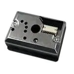
Compact Optical Dust Sensor
■ Description
GP2Y1010AU0F is a dust sensor by optical sensing system. An infrared emitting diode (IRED) and an phototransistor are diagonally arranged into this device. It detects the reflected light of dust in air. Especially, it is effective to detect very fine particle like the cigarette smoke. In addition it can distinguish smoke from house dust by pulse pattern of output voltage.
■ Compliance
1. Compliant with RoHS directive (2002/95/EC)
■
Applications
1. Detecting of dust in the air. 2. Example: Air purifier, Air conditioner, Air monitor
■
Features
1. Compact, thin package (46.0 × 30.0 × 17.6 mm) 2. Low consumption current (Icc: MAX. 20 mA) 3. The presence of dust can be detected by the photometry of only one pulse 4. Enable to distinguish smoke from house dust 5. Lead-free and RoHS directive compliant
Notice The content of data sheet is subject to change without prior notice. In the absence of confirmation by device specification sheets, SHARP takes no responsibility for any defects that may occur in equipment using any SHARP devices shown in catalogs, data books, etc. Contact SHARP in order to obtain the latest device specification sheets before using any SHARP device. Sheet No.: E4-A01501EN Date Dec. 1. 2006 1 © SHARP Corporation
�GP2Y1010AU0F
■ Internal schematic
1 3 1 V-LED
Dust through hole
IRED
2 6
2 LED-GND 3 LED 4 S-GND 5 VO 6 VCC
Dust or Smoke particle
Amplifier Circuit
PD
(For sensitivity adjustment)
5 4
case
Rs
■ Outline Dimensions
46.0 2.0 (2.8)
(Unit : mm)
Marking portion
14.3
22.8
+ 0.5 − 0.3
φ 9 ± 0.15 Dust through hole
2.0
17.6
Connector: S6B-ZR-SM4A-TF by JST Mfg. Co., Ltd.
(3)
(0.7)
configuration 1 V-LED 2 LED-GND 3 LED 4 S-GND 5 Vo 6 Vcc 17.8 21.9
6 (34.8) 28.1 22.8 R2 13.4
1
14.3
14.0
(3)
(3)
φ 8 ± 0.15 Dust through hole
Hole for sensitivity adjustment of variable resistor
* Unspecified tolerance : ± 0.3 mm. The dimensions in parenthesis are shown for reference.
(3)
R2
R2
(9.3)
(3)
R2
Product mass : approx. 16 g
2.0 Terminal
20.0
30.0
Sheet No.: E4-A01501EN
2
�GP2Y1010AU0F
Marking information
Date code
GP2Y10 10 F
: Die stamp marking : Ink stamp marking
Date code (2 digit)
1st digit Year of production A.D. Mark 2000 0 2001 1 2002 2 2003 3 2004 4 2005 5 2006 6 2007 7 2008 8 2009 9 2010 0 : : 2nd digit Month of production Month Mark 1 1 2 2 3 3 4 4 5 5 6 6 7 7 8 8 9 9 10 X 11 Y 12 Z
repeats in a 10 year cycle
Country of origin
Philippines
Sheet No.: E4-A01501EN
3
�GP2Y1010AU0F
■ Absolute Maximum Ratings
(Ta=25°C) Parameter Supply voltage Input terminal voltage Operating temperature Soldering temperature Symbol V CC VLED Topr T sol Rating −0.3 to +7 −0.3 to VCC −10 to +65 −20 to +80 Unit V V °C °C
*1
*1 Open drain drive input
■Electro-optical Characteristics
(Ta=25°C, VCC=5V) Parameter Sensitivity Output voltage at no dust Output voltage range LED terminal current Consumption current Symbol K VOC VOH ILED ICC Conditions
*1 *2 *3 *2 *3
*2
RL =4.7kΩ LED terminal voltage = 0 *2 RL =∞
*2 *3
MIN. 0.35 0 3.4 − −
TYP. 0.5 0.9 − 10 11
MAX. Unit 0.65 V/(0.1mg/m3) V 1.5 V − mA 20 20 mA
*1 Sensitivity is specified by the amount of output voltage change when dust density changes by 0.1 mg/m3. And the dust density for detection is a value of the density of cigarette (MILD SEVEN®) smoke measured by the digital dust monitor (P-5L2: manufactured by SHIBATA SCIENTIFIC TECHNOLOGY LTD.). *2 Input condition is shown in Fig. 1 *3 Output sampling timing is shown in Fig. 2
■Recommended input condition for LED input terminal
Parameter Pulse Cycle Pulse Width Operating Supply voltage Symbol T PW VCC Value 10 ± 1 0.32 ± 0.02 5 ± 0.5 Unit ms ms V
Sheet No.: E4-A01501EN
4
�GP2Y1010AU0F
Fig. 1 Input Condition for LED Input Terminal
Pulse-driven wave form
GP2Y1010AU0F R=150Ω
1 3
ILED
T=10ms VCC PW=0.32ms
+
C=220μF
2
Fig. 2 Sampling Timing of Output Pulse
ON ILED Output pulse 0.28ms Sampling OFF
Fig. 3 Output Voltage vs. Dust Density
4
3
Output voltage (V)
2
1
0
0
0.2
0.4
0.6
0.8
Dust density (mg/m3)
Remarks : Please be aware that all data in the graph are just for reference and are not for guarantee.
Sheet No.: E4-A01501EN
5
�GP2Y1010AU0F
● Notes
1 Connection of case and GND Case material use conductive resin as cover case {printed model No.} and metal {test terminal side} as bottom cover. The metal case connects with GND in sensor. 2 Cleaning Please don’t do cleaning, because there is a case that this device is not satisfied with its characteristics by cleaning. 3 Pulse input range Please subject to recommendation as regard input condition for LED in order to keep reliability. 4 Dust adhesion There is a case that this product does not detect the dust density correctly, since the dust adhered to the inside of the dust through hole may project into the detecting space which consist of emitter and detector light axis. Please take the structure and mechanism of the equipment into consideration to avoid the influence of adhered dust. And when the dust is adhered, please consider the maintenance such as vacuuming or blowing off the dust by air. In addition, please pay attention to structure and placing location of the application to avoid any adhesive particle like oil, etc. to gets into the device. If it sticks to optical part, malfunction may occur. 5 Light output In circuit designing, make allowance for the degradation of the light emitting diode output that results from long continuous operation. (50% degradation/5 years) 6 Sensitivity adjustment VR VR for sensitivity adjustment is set up at shipping from sharp. Please do not touch the VR or Electro-optical characteristics specified on the specification will be invalid. 7 Resolution Please do not disassemble the device such as removing tapping screw and so on. Even if the device is reassembled, it may not satisfy the specification. 8 Application to fire alarm Please do not use this device for a fire alarm application. When using this device to application other than air purifying and equipment with air purifying function, please inform us before usage. 9 Noise influence If the sensor is located close to noise generator (ex. Electric dust collector, etc. ), the sensor output may be affected by leaded noise. On top of that noise from power supply line also may affect the sensor output. When desinging the system, please consider the effect from noise. 10 Vibration influence The sensor may change its value under mechanical oscillation. Before usage, please make sure that the device works normally in the application. 11 Incident light influence There is a case that the sensor output may be affected when outer-light comes through dust through hole on printed side. In order to avoid any influence from outer-light, please locate the printed side of sensor facing to inside of the application. 12 When inside of the sensor is moisturized, this product does not keep its proper function. Please design the application so that moisturization of the sensor does not happen.
Sheet No.: E4-A01501EN
6
�GP2Y1010AU0F
● Presence of ODC etc.
This product shall not contain the following materials. And they are not used in the production process for this product. Regulation substances : CFCs, Halon, Carbon tetrachloride, 1.1.1-Trichloroethane (Methylchloroform) Specific brominated flame retardants such as the PBB and PBDE are not used in this product at all. This product shall not contain the following materials banned in the RoHS Directive (2002/95/EC). • Lead, Mercury, Cadmium, Hexavalent chromium, Polybrominated biphenyls (PBB), Polybrominated diphenyl ethers (PBDE).
Sheet No.: E4-A01501EN
7
�GP2Y1010AU0F
Packing Specification
Pad Product trays (5 trays/case)
Connector
Product
(B)
Packing case
Packing tape
Tray
(A) (C)
Model number Quantity Inspection date
PACKING METHOD 1. Each tray holds 50 pieces. Packing methods are shown in (A). 2. Each box holds 5 trays. Pads are added to top (B). 3. The box is sealed with packing tape. (C) shows the location of the Model number, Quantity, and Inspection date. 4. Weight is approximately 5.6 kg
Sheet No.: E4-A01501EN
8
�GP2Y1010AU0F
■ Important Notices
· The circuit application examples in this publication are provided to explain representative applications of SHARP devices and are not intended to guarantee any circuit design or license any intellectual property rights. SHARP takes no responsibility for any problems related to any intellectual property right of a third party resulting from the use of SHARP's devices. · Contact SHARP in order to obtain the latest device specification sheets before using any SHARP device. SHARP reserves the right to make changes in the specifications, characteristics, data, materials, structure, and other contents described herein at any time without notice in order to improve design or reliability. Manufacturing locations are also subject to change without notice. · Observe the following points when using any devices in this publication. SHARP takes no responsibility for damage caused by improper use of the devices which does not meet the conditions and absolute maximum ratings to be used specified in the relevant specification sheet nor meet the following conditions: (i) The devices in this publication are designed for use in general electronic equipment designs such as: --- Personal computers --- Office automation equipment --- Telecommunication equipment [terminal] --- Test and measurement equipment --- Industrial control --- Audio visual equipment --- Consumer electronics (ii) Measures such as fail-safe function and redundant design should be taken to ensure reliability and safety when SHARP devices are used for or in connection with equipment that requires higher reliability such as: --- Transportation control and safety equipment (i.e., aircraft, trains, automobiles, etc. ) --- Traffic signals --- Gas leakage sensor breakers --- Alarm equipment --- Various safety devices, etc. (iii) SHARP devices shall not be used for or in connection with equipment that requires an extremely high level of reliability and safety such as: --- Space applications --- Telecommunication equipment [trunk lines] --- Nuclear power control equipment --- Medical and other life support equipment (e.g., scuba). · If the SHARP devices listed in this publication fall within the scope of strategic products described in the Foreign Exchange and Foreign Trade Law of Japan, it is necessary to obtain approval to export such SHARP devices. · This publication is the proprietary product of SHARP and is copyrighted, with all rights reserved. Under the copyright laws, no part of this publication may be reproduced or transmitted in any form or by any means, electronic or mechanical, for any purpose, in whole or in part, without the express written permission of SHARP. Express written permission is also required before any use of this publication may be made by a third party. · Contact and consult with a SHARP representative if there are any questions about the contents of this publication.
Sheet No.: E4-A01501EN
9
�