PQ6CU11X1APQ
PQ6CU11X1APQ
CMOS Step-up Chopper Regulator
Features
1.High switching voltage :MAX.30V (capable of driving max 4LEDs in series connection) 2.Switching current: 250mA 3.High frequency PWM control :1.2MHz 4.High efficiency(efficiency:85%) 5.Built-in overheat, overcurrent protection functions 6.Built-in soft start function 7.RoHS directive compliant
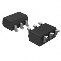
■ Outline Dimensions
( 1.9)
6 5 4
(Unit:mm)
C01
1 2 3
6–0.4±0.1 ( 0.95)
( 0.95)
1.1±0.2
Applications
1.Mobile phone 2.DSC 3.PDA Terminal
1.3M AX
( 0.3)
3.3M AX. ( 2 .9 T Y P. excluding remaining gate)
1.6±0.2
0~0.1
0.15±0.1
M 15° AX.
0.2M I N . 2.8±0.3
0.2M I N .
(
①Swith terminal (VSW) ②GND terminal ③Feed back terminal (FB) ④Control terminal (CTRL) ⑤OVP terminal (VO) ⑥VIN terminal(VIN)
) : Typical dimensions
Product mass:(0.015g)
Absolute Maximum Ratings
Parameter Input voltage Output voltage Switching voltage Control voltage Feed back voltage Switching current Power dissipation Junction temperature Operating temperature Storage temperature Soldering temperature Symbol
VIN VO VSW CTRL FB ISW Pd Tj Topr Tstg Tsol
(Ta=25°C)
Rating
6 30 30 VIN 6 250 350 150 -40 to +85 -40 to +150 260(10s)
Unit
V V V V V mA mW °C °C °C °C
Lead finish:Lead-free solder plating (Composition: Sn2Bi)
Operating conditions
Rating Parameter Symbol -40 to +125 Operating Junction temperature Tj Unit
°C
Notice The content of data sheet is subject to change without prior notice. In the absence of confirmation by device specification sheets, SHARP takes no responsibility for any defects that may occur in equipment using any SHARP devices shown in catalogs, data books, etc. Contact SHARP in order to obtain the latest device specification sheets before using any SHARP device.
1
Sheet No.: OP06059
�PQ6CU11X1APQ
Electrical Characteristics
Parameter Input-output voltage range Overvoltage detecting level Overvoltage detecting hysteresis level Quiescent current Stand-by current Efficiency Symbol VIN OVP OVP(hys) Iq ISD η VREF IFB fo DMAX IL RON ILEAK VC(ON) VC(OFF) ICTRL
(Unless otherwise specified,condition shall be VIN=VCTRL=3.6V,VO=10V,IO=20mA,Ta=25°C)
Conditions
MIN. 2.7 26
-
TYP.
-
MAX. 5.5 30
Unit V V V mA μA % mV nA MHz % mA Ω μA V V μA
5pin 5pin Switching,IO=0mA VCTRL=0V 3 LEDs
28 2 0.8 0.1 90 95 30 1.2
86
1.6 1
104 100 1.4
Error amplifier
Reference voltage FB pin bias current
VIN=3V DUTY=70%,Switching current peak ISW=250mA VSW=28V,VIN=VCTRL=0V
1 85 260
Oscillator
Oscillation frequency Maximum duty
1.7 0.05
2.5 1
Power switch
Overcurrent detection level On-resistance Leakage current
1
Control terminal
ON-state voltage for control OFF-state voltage for control CTRL pin bias current
L
-
-
0.4 50
Fig.1 Standard measuring circuit
22μH
D
A
VO
6
A
Iq Isd
1
IL ILEAK IO 5 R2 105.3kΩ
A
VIN CIN 2.2μF
A
IFB 4 ICTRL 2 VC 3
CO 1μF
V
R1 1kΩ
Vref
ON/OFF control logic
4pin LOW HIG H OPE N Output OFF ON OFF
L:VLP4612(TDK CO.,LTD.) D:MA2Z720(MATSUSHITA ELECTRIC INDUSTRIAL CO.,LTD)
Fig.2 Power Dissipation vs.Ambient Temperature
400
Fig.3 Reference Voltage Fluctuation vs. Junction Temperature
Reference voltage fluctuation ΔVREF (%)
1.0
VIN=VCTRL=3.6V L=22μH White LED:3LEDs IO=20mA
Pd : Mounting PCB
Power dissipation Pd (mW)
300
0.5
200
0
100
-0.5
-40 -25
0
0
25
50
75 85 100 125
150
-1.0 -50 -25
0
25
50
75
100
125
Ambient temperature Ta (°C)
Junction temperature Tj (°C)
Sheet No.: OP06059
2
�PQ6CU11X1APQ
Fig.4 Reference Voltage Fluctuation vs. Input voltage
Reference voltage fluctuation ΔVREF (%)
1.0
Fig.5 Efficiency vs. LED Current
100 95
Efficiency η (%)
0.5
90 85 80 75 70 65
0
-0.5
-1.0
3
3.2
3.4
3.6
3.8
4
4.2
60
5
10
15
20
Input voltage VIN (V)
LED current IO(mA)
Fig.6 Efficiency vs. Input Voltage
100 95
2LEDs
Fig.7 Oscillation Frequency Fluctuation vs. Junction Temperature
Oscillation frequency fluctuation ΔfO (%)
10
VIN=VCTRL=3.6V 3LEDs / 20mA CIN=2.2μF CO=0.1μF L=22μH
Efficiency η (%)
90 85 80 75 70 65 60 3 3.2 3.4 3.6 3.8 4 4.2
4LEDs 3LEDs
5
0
-5
-10 -50 -25
0
25
50
75
100
125
Input voltage VIN(V)
Junction temperature Tj (°C)
Fig.8 On-Resistance vs. Junction Temperature
5.0 4.5
Fig.9 ON/OFF-state Voltage for Control vs. Junction Temperature
1.0
ON/OFF-state voltage for control VC (V)
0.9 0.8 0.7 0.6 0.5 0.4 0.3 0.2 0.1 0 -50 -25 0 25 50
VIN=3.6V 3LEDs / 5mA CIN=2.2μF CO=0.1μF L=22μH
On-resistance RON (Ω)
4.0 3.5 3.0 2.5 2.0 1.5 1.0 0.5 0 -50 -25 0 25 50
VIN=VCTRL=3.6V VSW=3.6V ISW=250mA
75
100
125
75
100
125
Junction temperature Tj (°C)
Junction temperature Tj (°C)
Sheet No.: OP06059
3
�PQ6CU11X1APQ
Block Diagram
L D
VIN CIN
VIN
VSW
Soft start circuit
CTRL
ON/OFF Circuit
PWM CMP.
VO
Over voltage protection
ERROR AMP
95mV
CO
FB
Rset
Control Circuit OSC
Σ
GND
Example of application
22μH
L
D VSW
VIN
6
CTRL CIN 2.2μF
1 5 VO
VIN 3.6V
4 2
GND
3
FB
Rset 4.75Ω
CO 0.1μF IO 20mA
ON/OFF
■ Current-limit
This product monitors the switch current at every cycle and limits the switch current not to exceed the overcurrent detection level. Please set the white LED current under the maximum LED current shown in the graph indicated below within the range of input voltage (VIN) you use.
Fig.10 Use Range of White LED
140
Ta=25˚C VF=3.8V L=22μH
2LEDs
Maximum LED current (mA)
120 100 80 60 40 20 0 2.5
3LEDs 4LEDs 6LEDs
3
3.5
4
4.5
5
5.5
VIN(V)
Sheet No.: OP06059
4
�
很抱歉,暂时无法提供与“PQ6CU11X1APQ”相匹配的价格&库存,您可以联系我们找货
免费人工找货