0
登录后你可以
  • 下载海量资料
  • 学习在线课程
  • 观看技术视频
  • 写文章/发帖/加入社区
创作中心
发布
  • 发文章

  • 发资料

  • 发帖

  • 提问

  • 发视频

创作活动
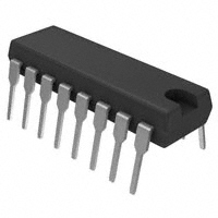
TCA785

TCA785

  • 厂商:

    SIEMENS

  • 封装:

  • 描述:

    TCA785 - Phase Control IC - Siemens Semiconductor Group

  • 数据手册
  • 价格&库存
TCA785 数据手册
TCA 785 Phase Control IC Pb-free lead plating; RoHS compliant Features q q q q q q q q TCA 785 Bipolar IC Reliable recognition of zero passage Large application scope May be used as zero point switch LSL compatible Three-phase operation possible (3 ICs) Output current 250 mA Large ramp current range Wide temperature range PG-DIP-16-1 Type TCA 785 Ordering Code Q67000-A2321 Package PG-DIP-16-1 This phase control IC is intended to control thyristors, triacs, and transistors. The trigger pulses can be shifted within a phase angle between 0 ˚ and 180 ˚. Typical applications include converter circuits, AC controllers and three-phase current controllers. This IC replaces the previous types TCA 780 and TCA 780 D. Pin Definitions and Functions Pin 1 2 3 4 5 6 7 8 9 10 11 12 13 Pin Configuration (top view) Semiconductor Group 14 15 16 1 Symbol GND Q2 QU Q2 VSYNC I QZ V REF R9 C10 V11 C12 L Q1 Q2 VS Function Ground Output 2 inverted Output U Output 1 inverted Synchronous voltage Inhibit Output Z Stabilized voltage Ramp resistance Ramp capacitance Control voltage Pulse extension Long pulse Output 1 Output 2 Supply voltage 02.05 TCA 785 Functional Description The synchronization signal is obtained via a high-ohmic resistance from the line voltage (voltage V5). A zero voltage detector evaluates the zero passages and transfers them to the synchronization register. This synchronization register controls a ramp generator, the capacitor C10 of which is charged by a constant current (determined by R9). If the ramp voltage V10 exceeds the control voltage V11 (triggering angle ϕ), a signal is processed to the logic. Dependent on the magnitude of the control voltage V11, the triggering angle ϕ can be shifted within a phase angle of 0˚ to 180˚. For every half wave, a positive pulse of approx. 30 µs duration appears at the outputs Q 1 and Q 2. The pulse duration can be prolonged up to 180˚ via a capacitor C12. If pin 12 is connected to ground, pulses with a duration between ϕ and 180˚ will result. Outputs Q 1 and Q 2 supply the inverse signals of Q 1 and Q 2. A signal of ϕ +180˚ which can be used for controlling an external logic,is available at pin 3. A signal which corresponds to the NOR link of Q 1 and Q 2 is available at output Q Z (pin 7). The inhibit input can be used to disable outputs Q1, Q2 and Q 1 , Q 2 . Pin 13 can be used to extend the outputs Q 1 and Q 2 to full pulse length (180˚ – ϕ). Block Diagram Semiconductor Group 2 TCA 785 Pulse Diagram Semiconductor Group 3 TCA 785 Absolute Maximum Ratings Parameter Supply voltage Output current at pin 14, 15 Inhibit voltage Control voltage Voltage short-pulse circuit Synchronization input current Output voltage at pin 14, 15 Output current at pin 2, 3, 4, 7 Output voltage at pin 2, 3, 4, 7 Junction temperature Storage temperature Thermal resistance system - air Operating Range Supply voltage Operating frequency Ambient temperature VS f TA 8 10 – 25 18 500 85 V Hz ˚C Symbol min. VS IQ V6 V11 V13 V5 VQ IQ VQ Tj Tstg Rth SA – 55 – 0.5 – 10 – 0.5 – 0.5 – 0.5 – 200 Limit Values max. 18 400 VS VS VS ± Unit V mA V V V µA 200 VS 10 VS 150 125 80 V mA V ˚C ˚C K/W Characteristics 8 ≤ VS ≤ 18 V; – 25 ˚C ≤ TA ≤ 85 ˚C; f = 50 Hz Parameter Supply current consumption S1 … S6 open V11 = 0 V C 10 = 47 nF; R 9 = 100 kΩ Synchronization pin 5 Input current R 2 varied Offset voltage Control input pin 11 Control voltage range Input resistance Semiconductor Group Symbol min. IS 4.5 Limit Values typ. 6.5 max. 10 Unit Test Circuit mA 1 I5 rms ∆V5 30 30 0.2 15 4 200 75 V10 peak µA 1 mV 4 V kΩ 1 5 V11 R11 TCA 785 Characteristics (cont’d) 8 ≤ VS ≤ 18 V; – 25 ˚C ≤ TA ≤ 85 ˚C; f = 50 Hz Parameter Ramp generator Charge current Max. ramp voltage Saturation voltage at capacitor Ramp resistance Sawtooth return time Inhibit pin 6 switch-over of pin 7 Outputs disabled Outputs enabled Signal transition time Input current V6 = 8 V Input current V6 = 1.7 V Deviation of I10 R 9 = const. VS = 12 V; C10 = 47 nF Deviation of I10 R 9 = const. VS = 8 V to 18 V Deviation of the ramp voltage between 2 following half-waves, VS = const. Long pulse switch-over pin 13 switch-over of S8 Short pulse at output Long pulse at output Input current V13 = 8 V Input current V13 = 1.7 V Outputs pin 2, 3, 4, 7 Reverse current VQ = VS Saturation voltage IQ = 2 mA Symbol min. I10 V10 V10 R9 tf 10 100 3 225 80 Limit Values typ. max. 1000 V2 – 2 350 300 Unit Test Circuit µA V mV kΩ µs 1 1.6 1 1 V6 L V6 H tr I6 H – I6 L I10 4 1 3.3 3.3 500 2.5 5 800 200 5 V V µs µA µA 1 1 1 1 1 1 80 –5 150 % % I10 – 20 20 1 ∆V10 max ± 1 % V13 H V13 L I13 H – I13 L 3.5 2.5 2.5 2 10 100 V V µA µA 1 1 1 1 45 65 ICEO Vsat 0.1 0.4 10 2 µA 2.6 2.6 V Semiconductor Group 5 TCA 785 Characteristics (cont’d) 8 ≤ VS ≤ 18 V; – 25 ˚C ≤ TA ≤ 85 ˚C; f = 50 Hz Parameter Outputs pin 14, 15 H-output voltage – I Q = 250 mA L-output voltage IQ = 2 mA Pulse width (short pulse) S9 open Pulse width (short pulse) with C12 Internal voltage control Reference voltage Parallel connection of 10 ICs possible TC of reference voltage Symbol min. V14/15 H V14/15 L tp tp VS – 3 0.3 20 530 Limit Values typ. VS – 2.5 0.8 30 620 max. VS – 1.0 2 40 760 Unit Test Circuit V V µs µs/ nF 3.6 2.6 1 1 VREF αREF 2.8 3.1 2 × 10 – 4 3.4 5 × 10 – 4 V 1 1/K 1 Semiconductor Group 6 TCA 785 Application Hints for External Components min Ramp capacitance C10 500 pF V11 × R9 × C10 VREF × K VREF × K R9 2) max 1 µF1) 2) The minimum and maximum values of I10 are to be observed Triggering point tTr = Charge current I10 = Ramp voltage V10 max = VS – 2 V V10 = VREF × K × t R9 × C10 2) Pulse Extension versus Temperature 1) 2) Attention to flyback times K = 1.10 ± 20 % Semiconductor Group 7 TCA 785 Output Voltage measured to + VS Supply Current versus Supply Voltage Semiconductor Group 8 TCA 785 It is necessary for all measurements to adjust the ramp with the aid of C10 and R 9 in the way that 3 V ≤ Vramp max ≤ V S – 2 V e.g. C10 = 47 nF; 18 V: R 9 = 47 kΩ; 8 V: R 9 = 120 kΩ Test Circuit 1 Semiconductor Group 9 TCA 785 The remaining pins are connected as in test circuit 1 Test Circuit 2 The remaining pins are connected as in test circuit 1 Test Circuit 3 Semiconductor Group 10 TCA 785 Remaining pins are connected as in test circuit 1 The 10 µF capacitor at pin 5 serves only for test purposes Test Circuit 4 Test Circuit 5 Semiconductor Group 11 Test Circuit 6 TCA 785 Inhibit 6 Long Pulse 13 Pulse Extension 12 Reference Voltage 8 Semiconductor Group 12 TCA 785 Application Examples Triac Control for up to 50 mA Gate Trigger Current A phase control with a directly controlled triac is shown in the figure. The triggering angle of the triac can be adjusted continuously between 0˚ and 180˚ with the aid of an external potentiometer. During the positive half-wave of the line voltage, the triac receives a positive gate pulse from the IC output pin 15. During the negative half-wave, it also receives a positive trigger pulse from pin 14. The trigger pulse width is approx. 100 µs. Semiconductor Group 13 TCA 785 Fully Controlled AC Power Controller Circuit for Two High-Power Thyristors Shown is the possibility to trigger two antiparalleled thyristors with one IC TCA 785. The trigger pulse can be shifted continuously within a phase angle between 0˚ and 180˚ by means of a potentiometer. During the negative line half-wave the trigger pulse of pin 14 is fed to the relevant thyristor via a trigger pulse transformer. During the positive line half-wave, the gate of the second thyristor is triggered by a trigger pulse transformer at pin 15. Semiconductor Group 14 TCA 785 Half-Controlled Single-Phase Bridge Circuit with Trigger Pulse Transformer and Direct Control for Low-Power Thyristors Semiconductor Group 15 TCA 785 Half-Controlled Single-Phase Bridge Circuit with Two Trigger Pulse Transformers for Low-Power Thyristors Semiconductor Group 16
TCA785 价格&库存

很抱歉,暂时无法提供与“TCA785”相匹配的价格&库存,您可以联系我们找货

免费人工找货