AMS00x-E03 Evaluation Guide
AMS00x-E03
Evaluation Guide
AMS001-E03
‘Bream’
ARG-AMS00x-E03-100R • AMS00x-E03 Evaluation Guide
©2014-2015 ACKme Networks Inc. http://ack.me
September 30, 2015
�AMS00x-E03 Evaluation Guide
Disclaimer
While the information provided in this document is
believed to be accurate, it is under development and
ACKme Networks reserves the right to make changes
without further notice to the product described herein
to improve reliability, function, or design, and makes no
guarantee or warranty concerning the accuracy of said
information, nor shall it be responsible for any loss or
damage of whatever nature resulting from the use of,
or reliance upon, such information. ACKme Networks
makes no warranties of any kind, whether express,
implied or arising by custom or course of trade or
performance, and specifically disclaims the implied
warranties of title, non-infringement, merchantability,
or fitness for a particular purpose.
No part of this document may be copied, reproduced,
stored in a retrieval system, or transmitted, in any form
or by any means, electronic, mechanical, photographic,
or otherwise, or used as the basis for manufacture or
sale of any items without the prior written consent of
ACKme Networks.
Trademarks
ACKme Networks and the ACKme Networks logo are
trademarks of ACKme Networks. WICED™ is a
trademark of Broadcom® Corporation, Inc. Other
trademarks in this document belong to their respective
owners.
Contact
http://ack.me/contact
About this User Guide
This guide provides information and basic usage
instructions for the TruConnect serial Bluetooth Low
Energy application and the family of AMS001/AMS002
‘Bobcat’ modules available from ACKme Networks.
Evaluation boards covered by this guide include:
AMS001-E03 ‘Bream’
Further information about TruConnect is available in the
TruConnect Reference manual online at:
http://truconnect.ack.me
Organization
This document is organized into the following sections:
Introduction
Feature Identification
Using TruConnect
Ordering Information
Revision History & Glossary
Appendix A – Setting up a Terminal Emulator
Appendix B – Evaluation Board Schematics
©2014-2015 ACKme Networks Inc.
All rights reserved.
Document Number: ARG-AMS00x-E03
Release Date: September 30, 2015
ARG-AMS00x-E03-100R • AMS00x-E03 Evaluation Guide
©2014-2015 ACKme Networks Inc. http://ack.me
Page | i
September 30, 2015
�AMS00x-E03 Evaluation Guide
Contents
1
Introduction ........................................................... 1
2
Feature Identification ............................................ 2
2.1
AMS001-E0x ‘Bream’ ...................................... 2
2.2
Power Supply .................................................. 3
Current Measurement ............................ 3
2.3
3
UART Selection ............................................... 3
Using TruConnect with Bobcat & Bream ............... 4
3.1
Getting Help.................................................... 4
3.2
Listing TruConnect Variables .......................... 5
3.3
Scanning for Bluetooth Peripherals ................ 5
3.4
Connecting to a Peripheral ............................. 5
3.5
Advertising as a Peripheral ............................. 5
3.6
Using GPIOs .................................................... 6
3.7
Save and Reboot ............................................. 6
3.8
Save Factory Settings ...................................... 7
3.9
Factory Reset .................................................. 7
3.10
Command vs. Stream Mode ........................... 7
Command Mode ..................................... 7
Stream Mode .......................................... 8
3.11
Want more? .................................................... 8
4
Ordering Information ............................................. 9
5
Revision History & Glossary .................................10
5.1
Revision History ............................................10
5.2
Glossary ........................................................10
APPENDIX A – Configuring a Terminal Application
APPENDIX B – Evaluation Board Schematics
ARG-AMS00x-E03-100R • AMS00x-E03 Evaluation Guide
©2014-2015 ACKme Networks Inc. http://ack.me
Page | ii
September 30, 2015
�AMS00x-E03 Evaluation Guide
Introduction
1
Introduction
The ‘Bobcat’ family of Bluetooth Low Energy modules are fully certified small form factor, low power modules
perfectly suited to deeply embedded wireless applications requiring low-power and low-cost in medium to high
volume.
Each module runs a fully-licensed version of TruConnect™, ACKme Networks’ easy-to-use and reliable serial
Bluetooth Low Energy application that provides a secure point-point wireless connection, rich peripheral interface
and various BLE profiles for wireless sensors and related products requiring Bluetooth Low Energy.
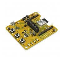
Evaluation of TruConnect and the Bobcat family of modules is available with the AMS00x-E03 ‘Bream’ evaluation
board. The evaluation board is shown in Figure 1 and its features are listed in Table 1.
Figure 1. AMS00x-E03 Bream
AMS001-E03 ‘Bream’
Table 1. AMS00x Evaluation Board Features
Feature
Product Number
Module style
Serial Interface for
comms and programming
Power supply options
User LEDs
AMS00x-E03 ‘Bream’
AMS00x-E03
Surface mount
USB-UART
USB +5V with current monitor
1 Red LED, 1 Green LED
User Buttons
2
Reset Button
Yes
Peripheral Header
3.3V UART, I2C, Power
Breakout Headers
2 x 11-pin
Isolation Header
2 x 10-pin
ARG-AMS00x-E03-100R • AMS00x-E03 Evaluation Guide
©2014-2015 ACKme Networks Inc. http://ack.me
Page | 1
September 30, 2015
�AMS00x-E03 Evaluation Guide
Feature Identification
2
2.1
Feature Identification
AMS001-E0x ‘Bream’
The Bream evaluation board comes complete with a surface mount AMS001 (or AMS002) ‘Bobcat’ module. Each pin
on the Bobcat module is connected to the expansion header. Schematics for the board are provided in Appendix B.
Figure 2. AMS001-E0x Features (TOP)
AMS00x Module
Breakout header H7
Breakout header H6
Peripheral header
Isolation header
UART selection switch
Power measurement
User UART Tx LED
User UART Rx LED
User LED 1* (red)
User LED 2* (green)
USB micro connector
Provides power to the board &
USB-Serial UART to computer
User Button 2*
User Button 1*
Reset Button
Used to reset the AMS00x module
* User configurable
Table 2. AMS001-E03 Expansion Header Connections
AMS00x
H6
AMS00x
H7
AMS00x
H14
AMS00x
H14
GND
1
GPIO 7
12
USER_RTS
1
GPIO 11
11
PROG_RX
2
GPIO 8
13
GPIO 7
2
LED 1
12
PROG_TX
3
GPIO 9
14
USER_RX
3
GPIO 12
13
GPIO 0
4
GPIO 10
15
GPIO 10
4
LED 2
14
GPIO 1
5
GPIO 11
16
USER_TX
5
RESET_N
15
GPIO 2
6
GPIO 12
17
I2C_SCL
6
RESET_BTN
16
GPIO 3
7
GPIO 13
18
USER_CTS
7
GPIO 6
17
RESET_N
8
GND
19
UART_RTS_USB
8
BUTTON 1
18
GPIO 4
9
GPIO 14
20
GPIO 3
9
GPIO 9
19
GPIO 5
10
VDD_DUT
21
UART_CTS_USB
10
BUTTON 2
20
GPIO 6
11
GND
22
ARG-AMS00x-E03-100R • AMS00x-E03 Evaluation Guide
©2014-2015 ACKme Networks Inc. http://ack.me
Page | 2
September 30, 2015
�AMS00x-E03 Evaluation Guide
Feature Identification
2.2
Power Supply
The board may be powered by various power sources listed in Table 3 .
Table 3. Bream Power Supply Sources
Power Supply
Source
USB
External 3.3V
Notes
+5V is supplied from the USB interface
External supply connected between H7 Pin 21 (+3.3V) and H7 Pin 19 (GND)
Current Measurement
The Bream board has an integrated current measurement circuit enabling current measurement with sub-milliamp
accuracy. To measure dynamic current, connect an oscilloscope to the yellow testhook labelled I=V/100 (the yellow
testhook is located near the middle of the board). To calculate the current used by the module, divide the voltage
measured by the oscilloscope by a factor of one hundred. For example, if the scope shows 1.1V, the current
consumed by the module is 11mA.
The integrated current measurement circuit is NOT suitable for measuring current in the low micro-amp range. To
measure ultra-low sleep currents, a suitable external ammeter should be placed in series with the AMS00x power
supply by connecting the ammeter to the jumper marked PWR_LINK.
2.3
UART Selection
The Bobcat module has two UARTs: a User UART for normal operation and a Programming UART. The Programming
UART is only used if the module requires a custom program or manual firmware upgrade. For most use cases, the
UART_SEL switch should be configured to the position marked USER.
To completely disconnect the AMS00x UART pins, move the switch to the center position. This may be necessary to
minimise current consumption in ultra-low power modes or if an external UART is connected to the expansion
header.
Note! If the UART is completely disconnected, the AMS00x PROG_TX pin (pin 3) may require a weak pull-up
to avoid excessive current consumption or unexpected wake from low power sleep mode.
ARG-AMS00x-E03-100R • AMS00x-E03 Evaluation Guide
©2014-2015 ACKme Networks Inc. http://ack.me
Page | 3
September 30, 2015
�AMS00x-E03 Evaluation Guide
Using TruConnect with Bobcat & Bream
3
Using TruConnect with Bobcat & Bream
The Bobcat module on the Bream evaluation board runs a licensed version of TruConnect, the flexible, easy-to-use
and intuitive Bluetooth Low Energy application from ACKme.
To get started with TruConnect, place the AMS001-E01 UART_SEL switch into the USER position, plug the evaluation
board into the USB port of the computer and open a terminal emulator as described in Appendix A. The USB cable
provides the Bobcat module and evaluation board with power and a serial UART connection to the computer.
With the board connected to the computer, verify the green LED is blinking slowly. If the LED does not blink, check
the UART switch is set to USER, then try re-plugging the USB cable, or try a different USB cable.
USB Serial
Computer with Terminal Emulator
Bream Evaluation Board
Note! The blue power LED illuminates when USB power is correctly supplied to the module. If the power
LED is illuminated, but the module is still not working, ensure a jumper is in place on the 2-pin header
marked PWR_LINK.
3.1
Getting Help
TruConnect help is available online at http://truconnect.ack.me
TruConnect operates in one of two serial bus modes: COMMAND mode, in which commands can be issued via a
remote or UART serial interface, and STREAM mode, in which TruConnect does not respond to commands and
instead passes characters to the Bluetooth wireless connection. The Bream platform is configured to boot
TruConnect into COMMAND mode by default.
For more details on stream mode and command mode, see Section 3.10 Command vs. Stream Mode.
TruConnect is configured in human command mode by default, in this mode, TruConnect should respond to a
carriage return with the following response:
Ready
>
If the response looks different, omitting the > characters for example, or characters entered into the terminal are not
echoed, then TruConnect may be in machine command mode. To return TruConnect to human command mode for
easy evaluation with a computer keyboard, enter the following commands:
> set sy c m human
> save
ARG-AMS00x-E03-100R • AMS00x-E03 Evaluation Guide
©2014-2015 ACKme Networks Inc. http://ack.me
Page | 4
September 30, 2015
�Using TruConnect with Bobcat & Bream
3.2
AMS00x-E03 Evaluation Guide
Listing TruConnect Variables
A list of all TruConnect variables is available by issuing the command: get al
> get al
bl a:
bl c c:
bl s u:
bl t a:
bl t c:
bl v m:
bl v h d:
bl v h i:
bl v l d:
bl v l i:
bu i:
…
3.3
4C55CC10066F
0
175f8f23-a570-49bd-9627-815a6a27de2a
0
4
low
30
32
300
1024
command
Scanning for Bluetooth Peripherals
To actively scan for any BLE peripheral in range using a high rate scan, use the scan all high command. Each
device within range is listed on a separate line.
> scan all high
Success
! # RSSI BD_ADDR
Device Name
# 1 -59 4C:55:CC:12:9a:42 AMS-9A42
# 2 -78 B8:E8:56:49:9F:9A Apple TV
To scan only for ACKme BLE peripherals in range (with the ACKme service UUID configured by the variable bl s u),
use the scan high command without the all argument. Each device within range is listed on a separate line.
> scan high
Success
! # RSSI BD_ADDR
Device Name
# 1 -59 20:73:7a:12:9a:42 AMS-9A42
Further information about the scan command is available online at http://truconnect.ack.me/commands#scan
3.4
Connecting to a Peripheral
To connect as a central to an ACKme BLE peripheral discovered during scanning, use the con command, with the
index number listed by the results of scan as an argument, e.g. :
> con 1
Success
To disconnect from the peripheral, use the dct command.
3.5
Advertising as a Peripheral
To make your ACKme BLE peripheral visible to other Bluetooth devices, use the advertise command:
> adv high
ARG-AMS00x-E03-100R • AMS00x-E03 Evaluation Guide
©2014-2015 ACKme Networks Inc. http://ack.me
Page | 5
September 30, 2015
�Using TruConnect with Bobcat & Bream
3.6
AMS00x-E03 Evaluation Guide
Using GPIOs
In TruConnect, pins on the Bobcat module may be configured to one of any number of functions including standard
IO, status indicator, status GPIO, serial bus mode select, control GPIO and a number of others.
Before a pin can be used, it is first necessary to check whether the GPIO is already in use for another purpose.
Use the get gp u command to see a list of GPIO functions. For example:
>
!
#
#
#
#
#
#
#
#
#
#
#
#
#
#
#
get gp u
# Description
0 i2c_sda
1 i2c_scl
2 user_tx
3 none
4 none
5 user_rx
6 none,factory
7 reserved
8 none
9 mode_sel
10 status_led
11 none
12 none
13 speaker
14 stream_gpio
The example below demonstrates how to assign the mode select function to GPIO 9 on the Bobcat module, after first
removing any previous function assigned to GPIO 9.
> gfu 9 none
Success
> gfu 9 mode_sel
Success
3.7
Save and Reboot
When the value of a TruConnect variable is changed, the new value is only saved to RAM (not flash!). The value of
unsaved variables is lost when the module is reset or rebooted. To save variables to non-volatile flash memory, use
the save command. The following example demonstrates that failing to save the variable value prior to reboot
results in the newly assigned value being lost:
get sy r
1
> set sy
Success
> get sy
0
> reboot
> get sy
1
> set sy
Success
> save
Success
> reboot
get sy r
0
e
r e 0
r e
r e
r e 0
e
ARG-AMS00x-E03-100R • AMS00x-E03 Evaluation Guide
©2014-2015 ACKme Networks Inc. http://ack.me
Page | 6
September 30, 2015
�AMS00x-E03 Evaluation Guide
Using TruConnect with Bobcat & Bream
Note! TruConnect configures some services (such as GPIO initialization) only after reboot. It may be
necessary to save and reboot the module before the new value of some variables takes effect.
3.8
Save Factory Settings
A custom factory configuration can be saved to non-volatile memory using the command:
save factory
The argument is required to ensure against accidental use of the command. To find the , use
the get bl a command.
If the factory settings are saved with the lock option, factory settings become permanent and may NEVER be
overwritten. Be sure to double check factory settings are correct before locking down factory settings!
3.9
Factory Reset
The Bobcat module may be factory reset using the fac (factory reset) command or by holding the factory reset pin
high for more than 10 seconds through a hardware reset. After a successful factory reset, all variables are set to
factory defaults and the module reboots. To avoid accidental factory reset, the device BLE address must be provided
when calling the fac command.
> get bl a
4C55CC10066F
> fac 4C55CC10066F
TruConnect-2.0.0.4, Built:Sep 11 2015 18:02:42, Module:AMS002.5, Board:AMS00x-E03.1
[COMMAND_MODE]
3.10 Command vs. Stream Mode
The TruConnect serial interface may be used in either Command Mode or Stream Mode. A brief description of each
of these modes is provided in the following text. For detailed information, please refer to the TruConnect Reference
Guide available online at http://truconnect.ack.me
Command Mode
Command mode provides an asynchronous command interface that a host may use to send and receive
configuration information. Command mode is typically used by a host to configure TruConnect. All preceding
examples demonstrate usage of TruConnect in command mode.
There are two ways to interact with TruConnect in command mode. When operating in human friendly command
mode, TruConnect provides verbose asynchronous responses that are easy for humans to read. In machine friendly
command mode, verbose prints and the command prompt are disabled and a well-defined response header is
returned after each command.
Configuring Command Mode
Command mode can be configured using the convenience variable sy c m equivalent to system.cmd.mode
Command
Description
set sy c m human
Enable human friendly command mode
set sy c m machine
Enable machine friendly command mode
ARG-AMS00x-E03-100R • AMS00x-E03 Evaluation Guide
©2014-2015 ACKme Networks Inc. http://ack.me
Page | 7
September 30, 2015
�AMS00x-E03 Evaluation Guide
Using TruConnect with Bobcat & Bream
Setting sy c m executes a macro that sets the value of the four variables used to switch between human and
command mode. These variables, together with the human and machine mode setting, are listed in the following
table.
Command
set sy p
Human /
Machine
Description
all
/
0
Set debug & informational print level
set sy c h
0
/
1
Disable/enable a response header
set sy c p
1
/
0
Turn on/off the user prompt
set sy c e
1
/
0
Turn on/off character echo. In human mode, lets you see what
you're typing
Enabling and Disabling Command Mode
A device can issue commands to TruConnect locally via the UART serial interface, or remotely via a wireless
connection. Only one device may have command mode access to TruConnect at any time.
A remote wireless device cannot place TruConnect in command mode when a local device is actively using the
command interface. Similarly, a local device cannot use command mode if a remote device is actively using the
command interface.
A local device or a remote device using TruConnect in command mode must put TruConnect into stream mode
before another device is allowed can use command mode. Access to command mode from a remote device can be
disabled with the set sy r e 0 command (set remote enable off).
Stream Mode
Stream Mode provides a streaming interface that transparently connects the Bobcat UART serial interface with a
remote device over a Bluetooth Low Energy wireless connection. Stream mode provides a simple 1-1 wireless
connection between the physical serial interface and a remote BLE device.
A wireless serial port is a typical application that uses stream mode.
3.11 Want more?
The TruConnect Reference Guide, available online at http://truconnect.ack.me, provides detailed information about
all TruConnect features, commands and variables, versions and release notes.
A number of simple and more sophisticated example applications are also provided to help you get the most out of
TruConnect and the Bobcat family of Bluetooth Low Energy modules.
ARG-AMS00x-E03-100R • AMS00x-E03 Evaluation Guide
©2014-2015 ACKme Networks Inc. http://ack.me
Page | 8
September 30, 2015
�AMS00x-E03 Evaluation Guide
Ordering Information, Section 4
4
Ordering Information
Table 4 provides ordering information for AMS00x-E03 evaluation boards.
Table 4. Ordering Information
Part Number
AMS00x-E03
‘Bream’
Picture
Description
TruConnect development and evaluation platform for the surface-mount
AMS00x module. The surface mount AMS00x module is not removable.
ARG-AMS00x-E03-100R • AMS00x-E03 Evaluation Guide
©2014-2015 ACKme Networks Inc. http://ack.me
Page | 9
September 30, 2015
�AMS00x-E03 Evaluation Guide
Revision History & Glossary, Section 5
5
5.1
Revision History & Glossary
Revision History
Table 5: Document Revision History
Revision
ARG-AMS00xE-100R
5.2
Date
Change Description
Sep 30, 2015
First release
Glossary
In most cases, acronyms and abbreviations are defined on first use. A comprehensive list of acronyms and other
terms used in ACKme Networks documents are provided on the ACKme Networks website at
http://ack.me/FAQs/Glossary.
ARG-AMS00x-E03-100R • AMS00x-E03 Evaluation Guide
©2014-2015 ACKme Networks Inc. http://ack.me
Page | 10
September 30, 2015
�Appendix A – Configuring a Terminal Emulator
AMS00x-E03 Evaluation Guide
APPENDIX A – Configuring a Terminal Application
The following instructions describe how to obtain and install a serial terminal application for use on computers
running a Windows® or OS X operations system. ACKme recommends using Tera Term for Windows® systems and
CoolTerm for OS X systems, however other equivalent applications may work equally well.
Plug the evaluation board into the computer using a USB cable before continuing.
Verify USB-Serial Driver Installation
The USB-Serial interface on TruConnect evaluation boards is based on an FTDI chip used widely in the industry. Most
operating systems including Windows®, OS X, and Linux provide integrated FTDI driver support as part of the
operating system. However on some older machines, or machines that do not pickup regular updates, the driver may
not automatically install and it is necessary to manually install the driver.
On computers running Windows®, check if the driver is installed as follows:
Display the System Control Panel (e.g. press the ‘Windows’ key + Pause key).
In the left-hand column near the top of the panel, click Device Manager
In the Device Manager dialog, expand the Ports (COM and LPT) branch
FTDI drivers appear under the USB Serial Port items. If no items of this kind appear, the drivers may
not be installed.
Note: The driver entry may not appear if the ACKme device is not connected to the USB port and
powered on.
Double click the USB Serial Port entry.
Select the General tab in the USB Serial Port Properties dialog. Check the following:
o Manufacturer: FTDI
o Device status: This device is working properly
Select the Driver tab in the USB Serial Port Properties dialog. Check the following:
o Driver Provider: FTDI
o Update drivers if necessary by clicking the Update Driver… button.
In some cases, the FTDI driver may actually be correctly installed, but the driver may not enumerate
as a Virtual Communications Port (VCP). If this is the case, find the device under the USB Serial Bus
controllers section of the Device manager, open the device, check the VCP box, then click OK. It may
be necessary to unplug/replug your evaluation board in order for the VCP driver to load correctly.
If the FTDI drivers do not appear to be installed, see the installation instructions on the FTDI official site:
http://www.ftdichip.com/Support/Documents/InstallGuides.htm
ARG-AMS00x-E03-100R • AMS00x-E03 Evaluation Guide
©2014-2015 ACKme Networks Inc. http://ack.me
Page | 11
September 30, 2015
�Appendix A – Configuring a Terminal Emulator
AMS00x-E03 Evaluation Guide
Set Up Tera Term for Windows®
Tera Term is available as a free download from http://ttssh2.sourceforge.jp. Download and install Tera Term now if
you have not already done so. The following procedure describes how to establish a UART serial connection between
Tera Term and the evaluation board.
1. Start the Tera Term application and click on the Setup tab. A
dropdown appears providing options to configure Tera Term as
shown in the screen capture on the right. Select Terminal.
2. Terminal Setup. In the New-line section of the Setup Terminal
dialog box (see the screen capture below), ensure that:
Receive: is set to CR
Transmit: is set to CR+LF
Close the Terminal Setup dialog box by selecting OK.
3. Serial Port Setup. Select the Setup tab again from the main window, then select Serial port. A Setup serial
port dialog box appears. Ensure the settings in the dialog box match the settings shown in the following
screen capture. The COM Port shown in the example (COM14) will almost certainly be different for your
evaluation board, be sure to choose the COM port that matches your board.
When the serial port has been correctly setup, close
the Serial port setup dialog box by selecting OK.
ARG-AMS00x-E03-100R • AMS00x-E03 Evaluation Guide
©2014-2015 ACKme Networks Inc. http://ack.me
Page | 12
September 30, 2015
�Appendix A – Configuring a Terminal Emulator
AMS00x-E03 Evaluation Guide
4. New Connection. From the Tera Term application menu,
setup a new connection with the evaluation board by
selecting File | New connection (or by pressing Alt + N) as
shown in the screen capture on the right. A New connection
dialog box appears as shown in the following screen capture.
Check the Serial radio button, then click the Port: dropdown
menu and select the COM port that matches your evaluation
board. The COM port description for the evaluation board
includes the text COMxx: USB Serial Port (COMxx).
Once the correct COM port has been selected, close the
New connection dialog box by selecting OK.
5. Testing the connection. If Tera Term was able to connect successfully, the text in the application title bar
indicates which COM port is connected, and the baud rate of the connection. For the example documented
above, Tera Term displays ‘COM14:115200baud’. The Tera Term screen remains blank however until a
character is sent to TruConnect. Try pressing the Enter key, TruConnect responds with Ready as shown in
the following screen capture.
ARG-AMS00x-E03-100R • AMS00x-E03 Evaluation Guide
©2014-2015 ACKme Networks Inc. http://ack.me
Page | 13
September 30, 2015
�Appendix A – Configuring a Terminal Emulator
AMS00x-E03 Evaluation Guide
Set Up CoolTerm for OS X
CoolTerm is available as a free download from http://freeware.the-meiers.org/CoolTermMac.zip. Download and
install CoolTerm now if you have not already done so.
The following procedure describes how to establish a UART serial interface between CoolTerm and the evaluation
board.
1. Start the CoolTerm application and click the
Options menu icon. The CoolTerm Configuration
window opens. Set the Serial Port configuration
options as follows:
Port: usbserial-XXXXXXXX
Baudrate: 115200
Data bits: 8
Parity: none
Stop bits: 1
Flow control : Deselect all options
2. Click OK.
3. Click the Connect menu icon. The CoolTerm
application connects to the evaluation board.
Try pressing the Enter key, if CoolTerm is successfully connected to the evaluation board, TruConnect responds with
Ready
>
ARG-AMS00x-E03-100R • AMS00x-E03 Evaluation Guide
©2014-2015 ACKme Networks Inc. http://ack.me
Page | 14
September 30, 2015
�Appendix B – Evaluation Board Schematics & Mechanical Dimensions
The schematic on this page is for Bream version 2 - AMS00x-E03.1. Schematics for other board revisions are available at http://ack.me/resources/show
1
2
3
4
5
6
7
8
" I s o la t i o n Ju m p er s "
VDD_3V3
D9
U3
VDD
H2
A
VDD _3V3
C4
100nF
C5
100nF
1
C2
47uF
2R
R2
220R
C3
47uF
R4
1k
D1
Blue
2
GND
PWREN_L
C8
USB1
3V3OUT
C9
27R
C10
47pF
GND
27R
R16
R17
7
1
USBDM
6
USBDP
3V3_USB
9
47pF
RESET#
C11
100nF
GND GND
CBUS0
CBUS1
CBUS2
CBUS3
GND
GND
EP
USB_DM
USB_DP
TXD
RXD
RTS#
CTS#
15
2
16
4
UART_ TX_USB
UART_ RX_USB
UART_ RTS_USB
UART_ CTS_USB
12
11 RX_LED
5 TX_LED
14 PWREN_L
" Per i p h er a l He ad er "
TP_I _ MON
GPI O3
I = V / 100
R21
0R
USER_RTS
USER_RX
USER_TX
USER_CTS
D NF
GND
GPI O4
R23
0R
R24
VD D_3V3
R9
R10
VDD _3V3
VDD_5V
H6
" Bl u et o o t h Lo w En er g y "
M1
GPI O0
GPI O1
GPI O2
GPI O3
GPI O4
GPI O5
GPI O6
GPI O7
GPI O8
GPI O9
GPI O10
GPI O11
GPI O12
USER_TX
USER_RX
GPI O13
GPI O14
R1
R7
GPI O0
GPI O1
GPI O8
GPI O4
GPI O3
GPI O11
GPI O12
RESET_N
GPI O6
GPI O9
4
5
6
7
9
10
11
12
13
14
15
16
17
18
20
D NF
D NF
R8
0R
R18
0R
GPI O0 /
GPI O1 /
GPI O2 /
GPI O3 /
GPI O4 /
GPI O5 /
GPI O6 /
GPI O7
GPI O8 /
GPI O9 /
GPI O10
GPI O11
GPI O12
GPI O13
GPI O14
SDA
SCL
USER_TX / SPI _MOSI ( s) / AD C
USER_RTS / SPI _MI SO( s) / ADC
USER_CTS / SPI _CLK( s)
USER_RX / SPI _CS( s)
SPI _MOSI ( m )
PROG_ RX
PROG_TX
RESET_N
VD D
GN D
GN D
GN D
GN D
GN D
GN D
GN D
GN D
SPI _MI SO( m )
SPI _CLK(m )
/ ADC / PWM
/ ADC / PWM
/ SPI _CS( m ) / ADC
/ ADC / PWM / XTALO32K
/ ADC / PWM / XTALI 32K
2
3
8
GND
PROG_RX
PROG_TX
RESET_N
21
VDD_DUT
1
19
22
23
24
25
26
27
C20
100nF
C21
10uF
GND
GPI O1 4
GPI O1 3
GPI O1 2
GPI O1 1
GPI O1 0
GPI O9
GPI O8
GPI O7
GND
C
" Use r LED ' s"
ACKm e - Bobcat ( AMS001)
GND
10pF
" Res et Bu t t o n "
LED_2
LED_1
LED_G
" Bu t t o n 2 "
VDD_3V3
S2
S3
LED_R
RESET_BTN
BUTTON_1
BUTTON_2
R15
47k
S1
R11
47k
GND
10pF
GND
VD D_3V3
R14
47k
Red
C15
" Bu t t o n 1 "
VDD _3V3
D7
D5
Green
X1
32.768kHz
SPI _MOSI
SPI _SCK
I 2C_ENABLE
UART_RTS_USB
UART_CTS_USB
LED _1
LED _2
RESET_BTN
BUTTON_1
BUTTON_2
2
4
6
8
10
12
14
16
18
20
VDD_DUT
H7
R19 10M
C14
1
3
5
7
9
11
13
15
17
19
H1
22
21
20
19
18
17
16
15
14
13
12
R13 220R
1
2
3
4
5
6
7
8
9
10
11
B
H14
R12 220R
C
PROG_RX
PROG_TX
GPI O0
GPI O1
GPI O2
GPI O3
RESET_N
GPI O4
GPI O5
GPI O6
VD D_5V
" I s o la t i o n Ju m p er s "
VD D_D UT
R20
10k
GND
VD D_3V3
Gr een
GND
GND
GPI O7
GPI O10
I 2C_SCL
I 2C_ SD A
1
2
3
4
5
6
7
8
9
10
11 12
13 14
15 16
GND
D NF
220R
220R
GND
GND
4
NC7WB66L8X
GN D
C13
100nF
SW1
Green
D2
D3
GND
GND
R22
PROG_ TX
I 2C_SD A
5
VDD _5V
I _MON
TP6
2
A
3
R6
10k
GND
1
TP5
PROG_ RX
USER_TX
U2
FT230XQ
I 2C_SCL
3
13
17
B
8
10nF
1
2
3
4
5
MH1
MH2
MH3
MH4
GND
3V3_USB
GND
USER_RX
10
GND
VCC
L1
220 Ohm @ 100MHz
Micr o USB B Socket
GND
C7
100nF
VCCIO
C6
4. 7uF
SPI _MOSI
GND
MAX4376 FAUK+ T
3
OUT
GND
3V3_USB
5V_USB
VCC
GND
100nF
6
1
TP2
U4
C12
8
7
I 2C_ENABLE
TP1
R5
2
ADJ
Vout
VD D_DUT
5
Vin
SN
D
3
4
VDD_5V
C1
100nF
G
R3
100k
LM1117MP- 3.3
U1
SP
Si2333DS ( P- Ch)
S
Q1
SPI _SCK
1
2
SM4005PL- TP
GN D
GND
GND
GND
" Bo o t f r o m ROM "
VDD_ DUT
GPI O0
1
2
TP9
TP10 TP11
GND
GND GND
Copy right 201 4, ACKm e Netw orks I nc.
h tt p: / / ack.m e
H3
Title:
D
D
Bream (AMS00x-E03)
ACKme Networks Pty Ltd
Size:
FI D1
FI D2
A3
FI D3
M2
1
2
3
ARG-AMS00x-E03-100R• AMS00x-E03 Evaluation Guide
©2014-2015 ACKme Networks Inc. http://ack.me
4
M3
M4
Document Number:
90-001-0048-010
M5
5
C Copyright
2 01 5
Rev.
1
Rev. Date: 1/04/2015
Sheet 1 of 1
6
7
8
Page | 15
September 30, 2015
�AMS00x-E03 Evaluation Guide
ACKme reserves the right to make changes without further notice to any products or data herein to improve reliability, function, or design.
Information furnished by ACKme is believed to be accurate and reliable. However, ACKme does not assume any liability arising out of the
application or use of this information, nor the application or use of any product described herein, neither does it convey any license under
its patent rights nor the rights of others.
ACKme Networks
Contact Information
+1 (408) 402 8601
http://ack.me/contact
US Headquarters
20 North Santa Cruz Ave
Los Gatos CA 95030
©2014-2015 ACKme Networks Inc. All rights reserved.
ARG-AMS00x-E03-100R • AMS00x-E03 Evaluation Guide
September 30, 2015
Phone:
�