C P 2 11 0 - E K
CP2110 E VALUATION K I T U SER ’ S G UIDE
1. Kit Contents
The CP2110 Evaluation Kit contains the following items:
CP2110
Evaluation Board
RS232 Serial Cable
USB Cable
Quick Start Guide
2. Relevant Documentation
Application notes can be found on the Interface Application Notes page for all fixed-function devices:
www.silabs.com/interface-appnotes.
AN721:
USBXpress™ Device Configuration and Programming Guide — Customize the VID, PID,
serial number, and other parameters stored in the CP2110 one-time programmable ROM.
AN433: CP2110/4 HID-to-UART API Specification— Provides function descriptions and examples for all
of the PC software functions that control the CP2110.
AN434: CP2110/4 Interface Specification — Describes the HID report format for CP2110 devices.
3. Software Setup
The Software Development Kit (SDK) packages and documentation for the CP2110 kit can be found on the device
page: (https://www.silabs.com/interface/usb-bridges/classic/device.cp2110-f02-gm1) and contains the following:
CP2110/4
Software packages (Software & Tools Tab)
USBXpress Host SDK (Software & Tools Tab)
Documentation: (Tech Docs tab)
CP2110
Data Sheets
User's Guide (this document)
Note: Follow the instruction to install the SDK to the system. The CP2110 is an HID device, so a driver does not need to be
installed on most operating systems.
CP2110
Rev. 0.4 1/21
Copyright © 2021 by Silicon Laboratories
CP2110-EK
�CP2110-EK
4. CP2110 Hardware Interface
Connect the CP2110 evaluation board to a PC as shown in Figure 1.
1. Connect one end of the USB cable to a USB Port on the PC.
2. Connect the other end of the USB cable to the USB connector on the CP2110 evaluation board.
3. Connect one end of the RS-232 serial cable to the DB-9 connector on the CP2110 evaluation board.
4. Connect the other end of the RS-232 serial cable to the target serial device.
USB
CP2110 HID USBto-UART Bridge
RS232
Serial Device
CP2110 EK
Figure 1. Hardware Setup
2
Rev. 0.4
�CP2110-EK
5. CP2110 Software Interface
The CP2110 is an HID device that uses the standard HID functions available in the operating system. To facilitate
this process in Windows, Silicon Labs packaged the standard HID functions into the SLABHIDDevice DLL in the
CP2110 software package. The HID report structure for the CP2110 is customized for the device and is not
compatible with other HID report structures, like a mouse or keyboard. AN434, “CP2110/4 Interface Specification”
describes the custom HID report structure for the CP2110, and AN433, “CP2110/4 HID-to-UART API Specification”
describes the API software functions that can be used to read or write data and control the CP2110 from the PC.
The software application described in “6. CP2110 Windows Application” provides an example of how to use these
functions.
The CP2110 appears as an HID device in Device Manager as shown in Figure 2.
Figure 2. CP2110 in Device Manager
Rev. 0.4
3
�CP2110-EK
6. CP2110 Windows Application
The HIDUart application is an example application that uses the Windows CP2110 HID-to-UART DLL to transmit
and receive data with the CP2110. The application also has access to the CP2110’s GPIO pins. The HIDUart
application is installed as part of the SDK installation process (Section 3). The following steps describe how to start
the application and use some of the features.
1.
Ensure that the hardware is connected to a Windows PC as shown in Section 4. If the device is properly connected,
the red SUSPEND LED on the CP2110 evaluation board will turn on.
2.
Launch the HIDUart application, which is found by clicking Start→All Programs→Silicon Laboratories→HIDUart
Example.
3.
In the application, configure the baud rate, data bits, parity, stop bits, and type of flow control using the drop-down
menus. This configuration should match the communication settings used by the serial device.
4.
Click Connect to start communication between the application and the CP2110 evaluation board. Once connected, the
USB descriptors retrieved from the device are shown under Device Information.
4
5
6
7
Figure 3. HIDUart Example Application after Connection
4
5.
Type data in the Transmit text box and click Transmit to send data from the PC to the serial device.
6.
Send data from serial device to the PC. Any data sent by the serial device to the PC is automatically updated in the
Receive text box.
7.
The HIDUart example automatically recognizes how the GPIO pins are configured and enables/disables the ability to
change and read the pin. The default configuration is shown in Figure 3. Use the Get and Set buttons to read and write
the GPIO pins’ latch values. For GPIO pins that are configured as outputs, setting the pin to logic low 0 will turn on the
corresponding LED on the CP2110 evaluation board.
Rev. 0.4
�CP2110-EK
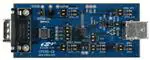
7. Evaluation Board Overview
The CP2110 Evaluation Kit includes an evaluation board with a CP2110 device pre-installed for evaluation and
preliminary software development. Numerous input/output (I/O) connections are provided to facilitate prototyping
using the evaluation board. Refer to Figure 4 for the locations of the various I/O connectors.
P1
P2
J1
J2
J3
J4
J5
J6
J7
J8
J9
J12
DB9 connector for RS-232 interface
USB connector for USB interface
UART signal access connector
VDD and VIO power connectors
GPIO0 and GPIO1 LED connectors
GPIO2 and GPIO3 LED connectors
GPIO4 and GPIO5 LED connectors
GPIO6 and GPIO7 LED connectors
GPIO8 and GPIO9 LED connectors
REGIN pin power connector
SUSPEND RED LED connector
Self-Power mode VDD and GND access connectors
J9
D10
D6
D7
J5
J1
U2
U1
J12
J8
P2
J2
SILICON LABS
P1
CP2110-EB
J4
D1
D0
J3
D3 J7
D2
D5
D4
D9 J6
D8
www.silabs.com
Figure 4. CP2110 Evaluation Board with Default Shorting Blocks Installed
7.1. LED Headers (J3, J4, J5, J6, J7)
Connectors J3, J4, J5, J6, and J7 are provided to allow access to the 10 GPIO pins on the CP2110. Place shorting
blocks on these headers to connect the GPIO pins to the 10 green LEDs D0 - D9. These LEDs can be used to
indicate active communications through the CP2110. Table 1 shows the LED corresponding to each header
position.
Table 1. J2 and J3 LED Locations
LED
Pins
LED
Pins
GPIO0-D0
J3[3:4]
GPIO5-D6
J5[1:2]
GPIO1-D1
J3[1:2]
GPIO6-D4
J6[3:4]
GPIO2-D2
J4[3:4]
GPIO7-D5
J6[1:2]
GPIO3-D3
J4[1:2]
GPIO8-D8
J7[3:4]
GPIO4-D7
J5[3:4]
GPIO9-D9
J7[1:2]
Rev. 0.4
5
�CP2110-EK
7.2. Universal Serial Bus (USB) Interface (P2)
A Universal Serial Bus (USB) connector (P2) is provided to facilitate connections to the USB interface on the
CP2110. See Table 2 for the USB pin definitions.
Table 2. USB Connector Pin Descriptions
Pin #
Description
1
2
3
4
VBUS
D–
D+
GND (Ground)
7.3. UART Signals (P1, J1)
An RS-232 transceiver circuit and DB9 connector (P1) are provided on the evaluation board to connect the CP2110
virtual serial port to external serial devices. See Table 3 for the RS-232 (P1) pin descriptions. The J1 connector is
provided to facilitate direct access to the CP2110’s UART signals. Shorting blocks on J1 are required to connect
the UART signals to the USB connector (P2). See Table 4 for J1 pin descriptions.
Table 3. RS-232 Pin Descriptions
Pin
Signal
2
3
5
7
8
RXD
TXD
GND
RTS
CTS
CP2110
Direction
Input
Output
Output
Input
Description
Receive Data
Transmit Data
Ground
Request to Send
Clear to Send
Table 4. J1 Pin Descriptions
6
Pins
Signal
1-2
3-4
5-6
7-8
TXD
RXD
RTS
CTS
CP2110
Direction
Output
Input
Output
Input
Rev. 0.4
Description
Transmit Data
Receive Data
Request to Send
Clear to Send
�CP2110-EK
7.4. VDD and VIO Power Connector (J2)
This header (J2) is included on the evaluation board to provide several power options. The following describes the
function of each pin:
Pins
1,3: Connects CP2110 VIO input (pin 5) to CP2110 VDD (pin 6). Remove the shorting block to power
VIO from an external source.
Pins 2,4: Connects the main +VDD_A net to the CP2110 VDD (pin 6). The main +VDD_A net powers the
RS-232 transceiver on the evaluation board.
7.5. REGIN Power Connector and Self-Powered Mode Connector (J8, J12)
The J8 header is used to connect the CP2110 REGIN pin (pin 7) to the VBUS source from the USB connector
(default) or to the CP2110 VDD pin (pin 6). When connected to the VBUS source, the device is intended for buspowered operation. When connected to the CP2110 VDD pin, the device is intended for self-powered operation.
When in self-powered operation, an external power source can be connected to the J12 header to power the VDD
pin directly.
7.6. .SUSPEND LED Connector (J9)
The J9 header is used to connect the CP2110 SUSPEND pin (pin 17) to the D10 red LED. When the LED is on, the
device has enumerated with the PC operating normally. When the LED is off, the device has not yet enumerated or
is in the USB Suspend state.
Rev. 0.4
7
�Figure 5. CP2110 Evaluation Board Schematic
CP2110-EK
8. Schematic
8
Rev. 0.4
�CP2110-EK
DOCUMENT CHANGE LIST
Revision 0.3 to Revision 0.4
Updated
"Kit Contents" on page 1 to remove DVD.
"Relevant Documentation" on page 1.
Updated "Software Setup" on page 1.
Updated "Table 1" to remove duplicate GPIO4-7,
correct one of them to GPIO5-6.
Updated section "7.3 UART signals" to correct
RS232 P2 pin -> RS232 (P1) pin.
Updated section "7.4 VDD and VIO power
connector" to correct the header (J4) -> the header
(J2).
Updated
Revision 0.2 to Revision 0.3
Updated “1. Kit Contents” to change CD-ROM to
DVD.
Added “2. Relevant Documentation” and “5. CP2110
Software Interface”.
Updated “3. Software Setup” to point to the drivers
on the website.
Updated Figure 1.
Updated Figure 3 with numbered steps matching the
instructions in “6. CP2110 Windows Application”.
Rev. 0.4
9
�
很抱歉,暂时无法提供与“CP2110EK”相匹配的价格&库存,您可以联系我们找货
免费人工找货