m
en
de
d
fo
r
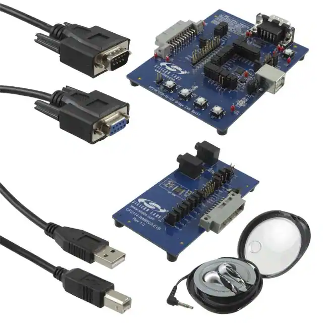
There are four CP2114 kits, and this document applies to all kits.
Kit Name
CP2114-EK
• External 48 MHz clock oscillator (supports
dual-clock configurations)
• Switches for controlling Playback Volume/
Mute, Record Mute
• UART interface: logic level or RS-232
(DB-9P)
• Status LEDs: Record Mute, UART activity,
USB Active/Suspend mode
• Config Select header: easy to select
between multiple configurations
• All required cables included. CODEC/DAC
kits also contain headphones.
Components
• CP2114 evaluation board
• USB cable
• RS-232 serial cable
CP2114 evaluation board
Daughter card with Cirrus Logic CS42L55 CODEC
Ear bud headphones
Audio cable (3.5 mm male to male)
USB Cable
RS-232 serial cable
CP2114-WM8523EK
•
•
•
•
•
CP2114 evaluation board
Daughter card with Cirrus Logic WM8523 DAC
Ear bud headphones
USB Cable
RS-232 serial cable
CP2114-PCM1774EK
•
•
•
•
•
CP2114 evaluation board
Daughter card with Texas Instruments PCM1774 DAC
Ear bud headphones
USB Cable
RS-232 serial cable
ec
R
N
ot
• All CP2114 pins routed to headers for
easy interface to external hardware
•
•
•
•
•
•
om
CP2114-CS42L55EK
KEY FEATURES
N
ew
The CP2114 simplifies the process of transferring audio data from USB to I2S without
any code development, speeding time to market for USB audio accessories such as
USB speakers, USB headphones and USB music boxes, as well as VoIP systems. The
CP2114 includes a USB 2.0 full-speed function controller, USB transceiver, oscillator,
I2S (audio) interface, I2C (control) interface and UART interface in a compact 5 x 5 mm
QFN-32 package ideal for space-constrained portable audio applications.
D
The CP2114 evaluation kits are designed to showcase the various
features of the CP2114 USBXpress® devices.
es
ig
ns
UG245: CP2114 Evaluation Kit User's
Guide
silabs.com | Smart. Connected. Energy-friendly.
Rev. 0.2
�UG245: CP2114 Evaluation Kit User's Guide
Getting Started
1. Getting Started
1.1 Getting Started with Windows
N
ew
D
es
ig
ns
1. Connect the CP2114 evaluation board to the daughter card.
2. Connect headphones and/or powered speakers to the appropriate daughtercard connector:
m
en
de
d
fo
r
• HP OUT: headphone output
• LINE OUT: line output (to powered speakers)
• HP/LINE OUT (WM8523 daughtercard only): common connector for headphone or line output.
om
3. Connect the USB cable to the CP2114 evaluation board (J2). Next, connect the other end of the USB cable directly to the host
computer.
N
ot
R
ec
Note: Do not use a USB hub.
4. Right-click on the [Speakers] icon in the Windows Systems Tray and left-click [Playback devices].
silabs.com | Smart. Connected. Energy-friendly.
Rev. 0.2 | 1
�UG245: CP2114 Evaluation Kit User's Guide
es
ig
ns
Getting Started
m
en
de
d
fo
r
N
ew
D
5. Select [CP2114 USB-Audio Bridge], click [Set Default] button. Next, verify the CP2114 is checked as the default playback device.
N
ot
R
ec
om
6. Play audio from the host computer using any media player application and verify high-quality audio from the headphones or powered speakers attached to the daughter card.
7. To adjust the volume or mute, right-click on the [Speakers] icon and left-click [Open Volume Mixer].
silabs.com | Smart. Connected. Energy-friendly.
Rev. 0.2 | 2
�UG245: CP2114 Evaluation Kit User's Guide
Getting Started
1
3
4
es
ig
ns
2
D
8. Set volume and mute. Volume and mute can be controlled in two ways, and both methods are supported by the CP2114.
Device
Volume
2
m
en
de
d
1
fo
r
Audio Source Volume
N
ew
a. Device Volume and Mute: this control sends USB volume and mute control messages to the device. Generally, this will adjust
the volume control of the DAC in hardware using I2C writes.
b. Audio Source Volume and Mute: these controls scale the audio signal sent over USB and can be set individually. The CP2114
volume can be set with these controls.
Device
Mute
om
Audio Source Mute
9. To set up the audio input, connect a powered microphone or line-level analog audio source to the analog In (AIN) connector (P2).
N
ot
R
ec
Note: Audio Input is supported only on the CS42L55 daughtercard, not the WM8523 and PCM1774 daughtercards. Although the
PCM1774 daughtercard has an ANALOG IN jack, this audio is not digitized and sent to the host because the PCM1774 is a DAConly device. The PCM1774 has the ability to mix the ANALOG IN signal with the analog output produced by its DAC.
silabs.com | Smart. Connected. Energy-friendly.
Rev. 0.2 | 3
�UG245: CP2114 Evaluation Kit User's Guide
Getting Started
10. Right-click on the [Speakers] icon and left-click on [Recording devices].
es
ig
ns
2
m
en
de
d
fo
r
N
ew
D
Open a recorder application to record the audio input or listen in real time by selecting [Properties] and checking the [Listen to
this device] button. Select the CP2114 from the [Playback through this device] drop-down to select full loop testing.
1.2 Getting Started with Mac OSX
N
ot
R
ec
om
1. Connect the CP2114 evaluation board to the daughter card.
silabs.com | Smart. Connected. Energy-friendly.
Rev. 0.2 | 4
�UG245: CP2114 Evaluation Kit User's Guide
Getting Started
2. Connect the analog out jack (P3) to powered speakers or the headphone output (P4) to headphones. Connect a sound source to
the analog input jack (P2).
es
ig
ns
Analog out
to powered
speakers
Headphone
output to
headphones
N
ew
D
Analog input
m
en
de
d
fo
r
3. Connect one end of the USB cable to the CP2114 evaluation board and the other end to the Mac.
4. Hold Option and click the speaker icon. Select the CP2114 as the sound output and the input device for the Mac.
R
ec
om
You can now play (audio out) or record (audio in) through the CP2114.
N
ot
5. There are two methods to adjust volume.
a. Mac TaskBar—This sends USB Audio Class “Set” volume messages over USB to the CP2114. The CP2114 forwards these
volume adjustments to the DAC via I2C and the DAC adjusts the gain. Currently, volume adjustments are sent to both the
DAC headphone output and the line-out output.
b. iTunes Volume—This causes the Mac to directly scale the audio samples that are sent over USB. It does not send USB Audio
class volume messages. This volume affects both headphone and line-out volumes.
silabs.com | Smart. Connected. Energy-friendly.
Rev. 0.2 | 5
�UG245: CP2114 Evaluation Kit User's Guide
D
es
ig
ns
Getting Started
N
ew
1.3 Getting Started with an iOS Device
N
ot
R
ec
om
m
en
de
d
fo
r
1. Connect the CP2114 Motherboard and Daughtercard together.
2. Connect the LINE OUT jack (P3) to powered speakers and/or the HP OUT jack (P4) to headphones.
3. Connect an analog audio source to the AIN jack (P2). The audio source can be an iPod, iPhone, MP3 player, CD player, stereo
microphone, etc.
4. Connect a Lightning-to-USB Camera Adapter to the CP2114 EVB and iPad. It is not necessary to manually select the CP2114 as
the playback device; whenever a CP2114 is connected to the iPad, the audio data will be automatically routed to the CP2114.
5. To demonstrate CP2114 audio output, open an iOS application that plays audio files (e.g. iPod, iTunes, etc.) and play an audio file.
The audio should be present on the headphone HP OUT (headphone) and LINE OUT jacks.
6. Adjusting the App volume slider sends USB Audio Class “Set” volume messages over USB to the CP2114. The CP2114 forwards
these volume adjustments to the DAC via I2C and the DAC adjusts the gain.
7. To demonstrate CP2114 audio input, open an iPad application that records audio files (e.g. GarageBand, QuickVoice, etc.). Begin
recording, then play audio on the audio source.
silabs.com | Smart. Connected. Energy-friendly.
Rev. 0.2 | 6
�UG245: CP2114 Evaluation Kit User's Guide
Getting Started
iPad
es
ig
ns
L
U
A
D
Line out
(P3) to powered
speakers
Analog input
(P2) to audio
source
N
ot
R
ec
om
m
en
de
d
fo
r
Audio source
N
ew
Headphone
output (P4) to
headphones
silabs.com | Smart. Connected. Energy-friendly.
Rev. 0.2 | 7
�UG245: CP2114 Evaluation Kit User's Guide
Relevant Documentation
2. Relevant Documentation
The following documents are applicable to CP2114 devices:
es
ig
ns
• AN721: CP210x/CP211x Device Customization Guide — This application note guides developers through the configuration process
of USBXpress devices.
• AN433: CP2110/4 HID-to-UART API Specification — This application note describes the Application Programming Interface (API) of
the dynamic libraries provided by Silicon Labs. Using these dynamic libraries is the quickest and easiest way to develop custom
software applications for the CP2114.
• AN434: CP2110/4 Interface Specification — This application note describes the CP2114 device interface, i.e. the format of the USB
vendor-specific reports used to configure and control the CP2114. This document can be used as a debugging resource, or to develop custom software applications on environments for which no dynamic library is provided.
• CP2114 Data Sheet
• CP2114 Evaluation Kit User's Guide (this document)
• CP2114 Quick Start Guide
D
The example applications as well as additional documentation can be found here: www.silabs.com/CP2114.
N
ot
R
ec
om
m
en
de
d
fo
r
N
ew
Application Notes can be accessed on the Silicon Labs website (www.silabs.com/interface-appnotes) or in Simplicity Studio using the
[Getting Started]>[Application Notes] area of the launcher.
silabs.com | Smart. Connected. Energy-friendly.
Rev. 0.2 | 8
�UG245: CP2114 Evaluation Kit User's Guide
CP2114 Hardware Overview
3. CP2114 Hardware Overview
For information on using the CP2114, see the CP2114 Quick Start Guide, available at www.silabs.com/CP2114.
N
ot
R
ec
om
m
en
de
d
fo
r
N
ew
D
es
ig
ns
The following figures show each evaluation board as well as important features.
silabs.com | Smart. Connected. Energy-friendly.
Rev. 0.2 | 9
�UG245: CP2114 Evaluation Kit User's Guide
CP2114 Hardware Overview
es
ig
ns
RS-232
Connector
USB Active
and Suspend
LEDs
fo
r
N
ew
D
Config Select
Jumpers
Microphone Input
Path
US
Co
TX and R
Toggle L
N
ot
R
ec
om
m
en
de
d
er
rd
or
Volume Control
Buttons
Figure 3.1. CP2114 Evaluation Board Features
silabs.com | Smart. Connected. Energy-friendly.
Rev. 0.2 | 10
�UG245: CP2114 Evaluation Kit User's Guide
CP2114 Hardware Overview
es
ig
ns
Line Out
Connector
Headphone
Out
Connector
N
ew
D
CS42L55
CODEC
Daughter
Card
Connector
m
en
de
d
fo
r
Analog Input
Connector
N
ot
R
ec
om
Figure 3.2. CS42L55 Daughter Card Features
silabs.com | Smart. Connected. Energy-friendly.
Rev. 0.2 | 11
�UG245: CP2114 Evaluation Kit User's Guide
CP2114 Hardware Overview
es
ig
ns
Line Out
Connector
Headphone
Out
Connector
m
en
de
d
fo
r
N
ew
D
WM8523
DAC
Daughter
Card
Connector
N
ot
R
ec
om
Figure 3.3. WM8523 Daughter Card Features
silabs.com | Smart. Connected. Energy-friendly.
Rev. 0.2 | 12
�UG245: CP2114 Evaluation Kit User's Guide
CP2114 Hardware Overview
es
ig
ns
Analog Input
Connector
N
ew
D
Headphone/
Line Out
Connector
Figure 3.4. PCM1774 Daughter Card Features
R
ec
om
m
en
de
d
fo
r
PCM1774
DAC
Daughter
Card
Connecto
N
ot
Note: Analog audio signals connected to the ANALOG IN jack are not digitized and sent to the host, because the PCM1774 does not
contain an ADC (analog to digital converter). The PCM1774 has the ability to route the analog inputs to its headphone/line amplifiers,
which may be useful in some applications (e.g. digital music player that includes an analog FM tuner).
silabs.com | Smart. Connected. Energy-friendly.
Rev. 0.2 | 13
�UG245: CP2114 Evaluation Kit User's Guide
Audio Playback and Recording
4. Audio Playback and Recording
•
•
•
•
•
16-bit Play, 16-bit Record
24-bit Play-only
16-bit Play-only
24-bit Record-only
16-bit Record-only
The CP2114 EVB ships with three factory-programmed audio configurations at indices 0, 1, and 2:
Table 4.1. Factory-Programmed CP2114 Audio Configurations
Play / Record
0
CS42L55 (CODEC)
16-bit Play
USBCLK: 48 MHz Internal
16-bit Record
SYSCLK: 48 MHz Internal
16-bit Play
USBCLK: 48 MHz External
1
WM8523 (DAC)
Record disabled
2
PCM1774 (DAC)
16-bit Play
Mode
Asynchronous
Asynchronous
SYSCLK: 49.152 MHz Internal
USBCLK: 48 MHz External
Asynchronous
SYSCLK: 49.152 MHz Internal
fo
r
Record disabled
Clocking
D
External Device
N
ew
Index
es
ig
ns
The CP2114 can be configured to operate in any one of the following stereo (2-channel) Play/Record configurations:
Because the CP2114 uses the in-box USB and audio drivers for Windows/Mac/Linux, it requires no user-installed drivers. Any audio
application can be used to play or record audio data.
N
ot
R
ec
om
m
en
de
d
Note: The CP2114 should be connected directly to a USB port on the host computer, and not through a USB hub. (Many vendors of
USB audio interface devices prohibit or discourage the use of USB hubs with their devices, because hubs have been known to cause
audio corruption.) Be aware that on many host machines it is common to have multiple USB ports (and possibly internal USB devices)
connected to an internal hub, which is functionally equivalent to using an external hub and can therefore cause audio corruption. If experiencing audio corruption, it may be necessary to try connecting the CP2114 to other USB ports on the host computer.
silabs.com | Smart. Connected. Energy-friendly.
Rev. 0.2 | 14
�UG245: CP2114 Evaluation Kit User's Guide
Device Customization
5. Device Customization
N
ot
R
ec
om
m
en
de
d
fo
r
N
ew
D
es
ig
ns
Device customization for the CP2114 is described in detail in AN721: CP210x/CP211x Device Customization Guide. to be sent to the
CP2114 one-time programmable memory or RAM. The audio string is used by the CP2114 to configure the DAC/CODEC.
silabs.com | Smart. Connected. Energy-friendly.
Rev. 0.2 | 15
�UG245: CP2114 Evaluation Kit User's Guide
Evaluation Board Overview
6. Evaluation Board Overview
6.1 CP2114-EB Overview
Table 6.1. CP2114 Evaluation Board Component Overview
Component
Description
es
ig
ns
The CP2114 Evaluation Kit includes an evaluation board with a CP2114 device pre-installed for user evaluation and software development. Numerous input/output (I/O) connections are provided to facilitate prototyping using the evaluation board. Refer to Figure
6.1 CP2114 Evaluation Board with Default Shorting Blocks Installed on page 17 for the locations of the various I/O connectors.
Daughter card connector
J2
USB connector for USB interface
J3
DB9 connector for RS-232 interface
D
J1
CP2114 pin connector
JP40
VIO power connector
JP41
REGIN Power Connector and Self-Powered Mode Connector
JP42
Test point connector
JP43
Si500 enable connector
JP44
(JP44 is unused and can be jumpered or unjumpered)
Config Select jumpers
Green USB ACTIVE LED connector
m
en
de
d
JP46
fo
r
JP45
N
ew
JP00-JP30
JP47
Red USB SUSPEND LED connector
JP48
Daughter card reset connector
JP49
CP2114 GPIO signal header
JP50, JP52
Daughter card GPIO signal header
Red record mute LED
D3
Red receive toggle LED
D4
Red transmit toggle LED
om
D2
D5
Red USB SUSPEND LED
D6
Green USB ACTIVE LED
ec
SW1-SW4
Reset button
N
ot
R
SW5
Audio control buttons
silabs.com | Smart. Connected. Energy-friendly.
Rev. 0.2 | 16
�UG245: CP2114 Evaluation Kit User's Guide
Evaluation Board Overview
J3
Config Select
RESET
JP41
JP42
JP46
JP47
JP22
JP23
JP24
JP25
JP26
JP30
JP17
JP16
JP15
JP14
JP13
JP12
JP11
JP10
JP40
CP2114
J2
D
Si50
0
U1
D2
CP2114-EB
www.silabs.com
S3
VOL +
fo
r
PB MUTE REC MUTE VOL -
JP43
TXT
D4
D3
RXT
JP02
JP01
JP00
JP44
N
ew
U3
JP07
JP06
JP05
JP04
JP03
JP52
JP48
S5
JP20
JP21
JP50
JP49
JP45
J1
SUSPEND
D5
es
ig
ns
ACTIVE
D6
S4
S1
S2
m
en
de
d
Figure 6.1. CP2114 Evaluation Board with Default Shorting Blocks Installed
6.1.1 Daughter Card Connector (J1)
The J1 connector is used to connect to a CP2114 daughter card.
6.1.2 Universal Serial Bus (USB) Interface (J2)
om
A Universal Serial Bus (USB) connector (J2) is provided to facilitate connections to the USB interface on the CP2114. See Table 2 for
the USB pin definitions.
Pin #
Description
1
VBUS
2
D-
3
D+
4
GND (Ground)
ec
R
N
ot
Table 6.2. USB Connector Pin Descriptions
silabs.com | Smart. Connected. Energy-friendly.
Rev. 0.2 | 17
�UG245: CP2114 Evaluation Kit User's Guide
Evaluation Board Overview
6.1.3 UART Signals (J3)
An RS-232 transceiver circuit and DB9 connector (J3) are provided on the evaluation board to connect the CP2114 to external serial
devices. See Table 3 for the RS-232 J3 pin descriptions.
Table 6.3. RS-232 Pin Descriptions
CP2114 Direction
2
RXD
Input
3
TXD
Output
5
GND
—
7
RTS
Output
8
CTS
Input
Description
es
ig
ns
Signal
Receive Data
Transmit Data
Ground
Request to Send
Clear to Send
D
Pin
N
ew
6.1.4 CP2114 Pin Connectors (JP00-JP30)
The JP00-JP30 connectors connect and disconnect CP2114 pins from external circuits. By default, all of these jumpers are populated.
6.1.5 VIO Power Connector (JP40)
fo
r
This header (JP40) is included on the evaluation board to provide VIO power options. Populating the shorting block connects the
CP2114 VIO input (pin 6) to CP2114 VDD (pin 7). Remove the shorting block to power VIO from an external source and connect the
power source to pin 2 of the header.
6.1.6 REGIN Power Connector and Self-Powered Mode Connector (JP41)
m
en
de
d
The JP41 header is used to connect the CP2114 REGIN pin (pin 8) to the VBUS source from the USB connector (default) or to the
CP2114 VDD pin (pin 7). When connected to the VBUS source, the device is intended for buspowered operation. When connected to
the CP2114 VDD pin, the device is intended for self-powered operation. In self-powered operation, an external power source can be
connected to the JP41 header to power the VDD pin directly.
6.1.7 Test Point Connector (JP42)
The JP42 header contains test points and is not used in normal operation.
6.1.8 Si500 Enable Connector (JP43)
R
ec
om
The JP43 header controls the output of the external Si500 48 MHz CMOS clock, which must be enabled if either USBCLK or SYSCLK
are configured as external. Shorting pin 2 to pin 3 on the header will place the Si500 in powerdown mode, which disables its clock
output. Shorting pin 1 to pin 2 on the header will connect CP2114 VDD to the Si500 OE (output enable) pin which is active high, thus
always enabling the clock output. The current consumption of the Si500 (and other external clock devices) vastly exceeds the specified
maximum USB Suspend-mode current for bus-powered devices of 2.5mA, For systems that are bus-powered and require an external
clock, the /SUSPEND signal should be connected to the active-high clock enable signal so that the clock is disabled in Suspend mode.
On the CP2114 EVB this can be accomplished by connecting a wire jumper from JP43-2 to JP21-1. External clocks with an active-low
enable should be controlled by SUSPEND rather than /SUSPEND.
N
ot
6.1.9 Config Select Connector (JP45)
The JP45 header is used to select the CP2114 boot configuration after a reset. When a jumper is populated, the corresponding GPIO
pin in connected to ground. When a jumper is removed, the corresponding GPIO pin is weakly pulled high.
Note: If any of the four CFGSEL pins are configured for a function other than CFGSEL, the CP2114 will not use the Config Select pins
to choose a boot configuration. In that case, the current value of the OTP Boot Config element determines which configuration will be
loaded at powerup or reset.
silabs.com | Smart. Connected. Energy-friendly.
Rev. 0.2 | 18
�UG245: CP2114 Evaluation Kit User's Guide
Evaluation Board Overview
6.1.10 Green USB ACTIVE LED and Connector (JP46, D6)
The JP46 header is used to connect the CP2114 SUSPEND pin (pin 18) to the D6 green LED. When the LED is on, the device has
enumerated with the PC operating normally. When the LED is off, the device has not yet enumerated or is in the USB Suspend state.
6.1.11 Red USB SUSPEND LED and Connector (JP47, D5)
es
ig
ns
The JP47 header is used to connect the CP2114 /SUSPEND pin (pin 17) to the D5 red LED. When the LED is on, the device has
enumerated with the PC operating normally. When the LED is off, the device has not yet enumerated or is in the USB Suspend state.
6.1.12 Daughter Card Reset Connector (JP48)
The JP48 header connects RESET to the GPIO4_C pin on the daughter card connector (J1). On the CS42L55 daughter card,
GPIO4_C is connected to the CS42L55 RESET pin. The GPIO4_C pin is unconnected on the WM8523 and PCM1774 daughter cards
because these DACs do not have a hardware reset input. By default the JP48 jumper is installed, which results in the CS42L55 being
reset at powerup (when the CP2114 drives RESET), or whenever the Reset pushbutton is pressed.
N
ew
D
Note: If JP48 is jumpered, there must not be a jumper installed between JP49-5 (GPIO4) and JP50-3 (GPIO4_C), because this would
cause the CP2114 to be reset whenever GPIO4 was set to logic low.
6.1.13 CP2114 GPIO Signal Connector (JP49)
The connector JP49 provides easy access to all of the CP2114 GPIO signals.
6.1.14 Daughter Card Signal Header (JP50, JP52)
fo
r
The headers JP50 and JP52 allow the connection of GPIO0-4 signals to the corresponding daughter card signals (GPIOx_C). These
jumpers can be used to route the appropriate GPIO signals to a custom daughter card.
m
en
de
d
Note: If there is a jumper installed between JP49-5 (GPIO4) and JP50-3 (GPIO4_C), JP48 must not be jumpered because this would
cause the CP2114 to be reset whenever GPIO4 was set to logic low.
6.1.15 Audio Control Buttons and Red Record Mute LED (SW1-SW4, D2)
SW1 through SW4 send audio control commands when pressed. In addition, the red record mute LED (D2) will turn on when the record
mute button is pressed (SW4).
Table 6.4. Audio Control Buttons
Pins
S1
Volume-
S2
Volume+
S3
Playback Mute
S4
Record Mute
R
ec
om
LED
N
ot
6.1.16 Red Receive Toggle and Transmit Toggle LEDs (D3, D4)
The LEDs D3 and D4 will toggle when transmitting and receiving UART data. In order to use this functionality, the GPIO pins must first
be configured for TX Toggle and RX Toggle modes. By default, these pins are configured as CFGSEL0 and CFGSEL1.
6.1.17 Reset Button (SW5)
SW5 externally pulls the CP2114 reset pin (pin 10) low when pressed. If SW5 is held down, the CP2114 will remain in reset until the
button is released.
silabs.com | Smart. Connected. Energy-friendly.
Rev. 0.2 | 19
�UG245: CP2114 Evaluation Kit User's Guide
Evaluation Board Overview
6.2 CS42L55-EB Overview
The CS42L55 evaluation board contains a pre-installed CS42L55 for evaluation and preliminary software development with the CP2114
evaluation board. Refer to Figure 6.2 CS42L55 Evaluation Board with Default Shorting Blocks Installed on page 20 for the locations of
the various I/O connectors on the CS42L55-EB.
Component
Description
Daughter card connector
P2
Analog input connector
P3
Line output connector
P4
Headphone output connector
I2S/I2C signal connectors
J9, J10
I2S/I2C signal connectors
N
ew
J1-J5
D
P1
es
ig
ns
Table 6.5. CS42L55 Evaluation Board Component Overview
LINE OUT
fo
r
P3
J1
HP OUT
J2
m
en
de
d
P4
J4
P1
J3
J10
CS42L55
J9
ec
om
U1
AIN
P2
CP2114-CS42L55-EVB
www.silabs.com
Figure 6.2. CS42L55 Evaluation Board with Default Shorting Blocks Installed
N
ot
R
J5
6.2.1 Daughter Card Connector (P1)
The P1 connector is used to connect to a CP2114 evaluation board (CP2114-EB). The CS42L55-EB must be plugged into a CP2114
evaluation board to function properly.
6.2.2 Analog Input Connector (P2)
The P2 connector is used to connect an input device to the CS42L55 evaluation board.
silabs.com | Smart. Connected. Energy-friendly.
Rev. 0.2 | 20
�UG245: CP2114 Evaluation Kit User's Guide
Evaluation Board Overview
6.2.3 Line Output Connector (P3)
The P3 connector is used to connect powered speakers to the CS42L55 evaluation board.
6.2.4 Headphone Output Connector (P4)
The P4 connector is used to connect headphones to the CS42L55 evaluation board.
es
ig
ns
6.2.5 I2S/I2C Signal Connectors (JP1-JP5, JP9, JP10)
N
ot
R
ec
om
m
en
de
d
fo
r
N
ew
D
Connectors JP1 through JP7, JP9, and JP10 are provided to allow access to the I2S/I2C signals between the CP2114 and CS42L55.
Placing a shorting block between pins 1 and 2 will connect the CP2114 to the CS42L55. Placing a shorting block between pins 2 and 3
will connect the corresponding CS42L55 pin to ground. When monitoring the I2S signals, connect the scope probe ground lead to the
adjacent ground pin.
silabs.com | Smart. Connected. Energy-friendly.
Rev. 0.2 | 21
�UG245: CP2114 Evaluation Kit User's Guide
Evaluation Board Overview
6.3 WM8523-EB Overview
The WM8523 evaluation board contains a pre-installed WM8523 for evaluation and preliminary software development with the CP2114
evaluation board. Refer to Figure 6.3 WM8253 Evaluation Board with Default Shorting Blocks Installed on page 22 for the locations of
the various I/O connectors on the WM8523-EB.
Component
Description
Daughter card connector
J2
Line output connector
J3
Headphone output connector
JP2-JP10
I2S and I2C signal connectors
D
J1
es
ig
ns
Table 6.6. WM8253 Evaluation Board Component Overview
Voltage regulator input connector
JP12
WM8253 supply voltage header
JP13
WM8253 supply voltage connector
JP14
Headphone amplifier SHDN header
JP15
Ground header
N
ew
JP11
GPIO header for SHDN control
fo
r
JP16-JP20
JP15
JP12
JP13
m
en
de
d
HP OUT
J3
LINE OUT
JP9
JP10
JP14
JP11
J2
WM8523
JP7
JP8
JP6
JP3
R
N
ot
J1
JP5
U1
ec
om
JP19
JP20
JP16
JP17
JP18
JP4
JP2
CP2114-WM8523-EVB
www.silabs.com
Figure 6.3. WM8253 Evaluation Board with Default Shorting Blocks Installed
silabs.com | Smart. Connected. Energy-friendly.
Rev. 0.2 | 22
�UG245: CP2114 Evaluation Kit User's Guide
Evaluation Board Overview
6.3.1 Daughter Card Connector (J1)
The J1 connector is used to connect to a CP2114 evaluation board (CP2114-EB). The WM8253-EB must be plugged into a CP2114
evaluation board to function properly.
6.3.2 Line Output Connector (J2)
es
ig
ns
The J2 connector is used to connect powered speakers to the WM8253 evaluation board.
6.3.3 Headphone Output Connector (J3)
The J3 connector is used to connect headphones to the WM8253 evaluation board.
6.3.4 I2S/I2C Signal Connectors (JP2-JP10)
N
ew
D
Connectors JP2 through JP10 are provided to allow access to the I2S/I2C signals between the CP2114 and WM8253. Placing a shorting block between pins 1 and 2 will connect the CP2114 to the WM8253. Placing a shorting block between pins 2 and 3 will connect the
corresponding WM8253 pin to ground. When monitoring the I2S signals, connect the scope probe ground lead to the adjacent ground
pin.
6.3.5 Voltage Regulator Connector (JP11)
6.3.6 WM8253 Supply Voltage Header (JP12)
fo
r
The JP11 connector is used to connect the VBUS signal being supplied to the CP2114 to the input of the voltage regulator on the
WM8253 evaluation board. Installing this jumper connects the VBUS signal to the regulator output. If another voltage supply is used,
JP11 should be removed and the supply should be connected to pin 2 of the header.
The JP12 header provides access to the WM8253 supply voltage.
m
en
de
d
6.3.7 WM8253 Supply Voltage Connector (JP13)
This header (JP13) is included on the evaluation board to provide several power options for the WM8253. The following describes the
function of each pin:
• Shorting pins 1,2—Connects the regulator output on the WM8253-EB to the supply of the WM8253.
• Shorting pins 2,3—Connects the CP2114 VDD (CP2114 pin 7) to the supply of the WM8253.
6.3.8 Headphone Amplifier SHDN Header (JP14, JP16–JP20)
om
The jumpers JP14 and JP16-JP20 control the headphone amplifier shutdown (SHDN) pin. The headphone amplifier is enabled when
SHDN is high and disabled when SHDN is low. In the default configuration (jumper shorting pins1 and 2), the headphone amp is always
enabled. Shorting pins 2 and 3 on JP14 will disable the headphone amplifier. Removing JP14 and connecting one of JP16-JP20 allows
the host to control the headphone amp via GPIO pin. In this case, the corresponding GPIO-GPIO_C jumper must also be installed on
the CP2114-EK board.
ec
6.3.9 Ground Header (JP15)
N
ot
R
The JP15 header provides access to ground.
silabs.com | Smart. Connected. Energy-friendly.
Rev. 0.2 | 23
�UG245: CP2114 Evaluation Kit User's Guide
Evaluation Board Overview
6.4 PCM1774-EB Overview
The PCM1774 evaluation board includes contains a pre-installed a PCM1774 for evaluation and preliminary software development with
the CP2114 evaluation board. Refer to Figure 6.4 PCM1774 Evaluation Board with Default Shorting Blocks Installed on page 24 for
the locations of the various I/O connectors on the PCM1774-EB.
Component
Description
J1
Daughter card connector
J2
Headphone/line output connector
J3
Analog input connector
I2S signal connectors
D
JP1-JP7
es
ig
ns
Table 6.7. PCM1774 Evaluation Board Component Overview
Voltage regulator connector
JP9
PCM1774 supply voltage connector
N
ew
JP8
JP15, JP16
External capacitor connectors
J3
fo
r
ANALOG IN
JP9
m
en
de
d
HP/LINE OUT
JP8
J2
JP15 JP16
PCM1774
JP6
JP7
JP4
JP5
JP2
JP3
JP1
N
ot
R
ec
om
U1
J1
CP2114-PCM1774-EVB
www.silabs.com
Figure 6.4. PCM1774 Evaluation Board with Default Shorting Blocks Installed
6.4.1 Daughter Card Connector (J1)
The J1 connector is used to connect to a CP2114 evaluation board (CP2114-EB). The PCM1774-EB must be plugged into a CP2114
evaluation board to function properly.
6.4.2 Headphone/Line Output Connector (J2)
The J2 connector is used to connect headphones or powered speakers to the PCM1774 evaluation board.
silabs.com | Smart. Connected. Energy-friendly.
Rev. 0.2 | 24
�UG245: CP2114 Evaluation Kit User's Guide
Evaluation Board Overview
6.4.3 Analog Input Connector (J3)
The J3 connector is used to connect an input device to the PCM1774 evaluation board.
es
ig
ns
Note: Analog audio signals connected to the ANALOG IN jack are not digitized and sent to the host, because the PCM1774 does not
contain an ADC (analog to digital converter). The PCM1774 has the ability to route the analog inputs to its headphone/line amplifiers,
which may be useful in some applications (e.g. digital music player that includes an analog FM tuner).
6.4.4 I2S/I2C Signal Connectors (JP1–JP7)
Connectors JP1 through JP7 are provided to allow access to the I2S/I2C signals between the CP2114 and PCM1774. Placing a shorting block between pins 1 and 2 will connect the CP2114 to the PCM1774. Placing a shorting block between pins 2 and 3 will connect
the corresponding PCM1774 pin to ground. When monitoring the I2S signals, connect the scope probe ground lead to the adjacent
ground pin.
D
6.4.5 Voltage Regulator Connector (JP8)
N
ew
The JP8 connector is used to connect the VBUS signal being supplied to the CP2114 to the input of the voltage regulator on the
PCM1774 evaluation board. Installing this jumper connects the VBUS signal to the regulator output. If another voltage supply is used,
JP8 should be removed and the supply should be connected to pin 2 of the header.
6.4.6 PCM1774 Supply Voltage Connector (JP9)
This header (JP9) is included on the evaluation board to provide several power options for the PCM1774. The following describes the
function of each pin:
6.4.7 External Capacitor Connectors (JP15, JP16)
fo
r
• Shorting pins 1,2—Connects the regulator output on the PCM1774-EB to the supply of the PCM1774.
• Shorting pins 2,3—Connects the CP2114 VDD (CP2114 pin 7) to the supply of the PCM1774.
N
ot
R
ec
om
m
en
de
d
The JP15 and JP16 connectors allow external capacitors to be connected to the HP/LINE OUT connector. For best low frequency response (35 Hz cutoff), remove the jumpers on JP15 and JP16. For maximum power output (45 Hz cutoff), place the jumpers on JP15
and JP16.
silabs.com | Smart. Connected. Energy-friendly.
Rev. 0.2 | 25
�UG245: CP2114 Evaluation Kit User's Guide
Schematics and BOM
7. Schematics and BOM
N
ot
R
ec
om
m
en
de
d
fo
r
N
ew
D
es
ig
ns
The schematics and bill of materials (BOM) for the CP2114 Evaluation Kit and the various daughter cards are available through Simplicity Studio when the kit documentation package has been installed. To access these documents, click the [Documentation] link after
selecting the device in the left pane or search for the document using the search bar at the top.
silabs.com | Smart. Connected. Energy-friendly.
Rev. 0.2 | 26
�UG245: CP2114 Evaluation Kit User's Guide
Revision History
8. Revision History
8.1 Revision 0.2
July 27th, 2016
Updated formatting.
es
ig
ns
Updated for CP2114-B02.
Added the UG245 document reference.
8.2 Revision 0.1
October 2012
N
ot
R
ec
om
m
en
de
d
fo
r
N
ew
D
Initial revision.
silabs.com | Smart. Connected. Energy-friendly.
Rev. 0.2 | 27
�es
ig
ns
D
N
ew
fo
r
One-click access to MCU and
wireless tools, documentation,
software, source code libraries &
more. Available for Windows,
Mac and Linux!
om
IoT Portfolio
www.silabs.com/IoT
m
en
de
d
Simplicity Studio
SW/HW
www.silabs.com/simplicity
Quality
www.silabs.com/quality
Support and Community
community.silabs.com
N
ot
R
ec
Disclaimer
Silicon Labs intends to provide customers with the latest, accurate, and in-depth documentation of all peripherals and modules available for system and software implementers using or
intending to use the Silicon Labs products. Characterization data, available modules and peripherals, memory sizes and memory addresses refer to each specific device, and "Typical"
parameters provided can and do vary in different applications. Application examples described herein are for illustrative purposes only. Silicon Labs reserves the right to make changes
without further notice and limitation to product information, specifications, and descriptions herein, and does not give warranties as to the accuracy or completeness of the included
information. Silicon Labs shall have no liability for the consequences of use of the information supplied herein. This document does not imply or express copyright licenses granted
hereunder to design or fabricate any integrated circuits. The products are not designed or authorized to be used within any Life Support System without the specific written consent of
Silicon Labs. A "Life Support System" is any product or system intended to support or sustain life and/or health, which, if it fails, can be reasonably expected to result in significant personal
injury or death. Silicon Labs products are not designed or authorized for military applications. Silicon Labs products shall under no circumstances be used in weapons of mass
destruction including (but not limited to) nuclear, biological or chemical weapons, or missiles capable of delivering such weapons.
Trademark Information
Silicon Laboratories Inc.® , Silicon Laboratories®, Silicon Labs®, SiLabs® and the Silicon Labs logo®, Bluegiga®, Bluegiga Logo®, Clockbuilder®, CMEMS®, DSPLL®, EFM®, EFM32®,
EFR, Ember®, Energy Micro, Energy Micro logo and combinations thereof, "the world’s most energy friendly microcontrollers", Ember®, EZLink®, EZRadio®, EZRadioPRO®,
Gecko®, ISOmodem®, Precision32®, ProSLIC®, Simplicity Studio®, SiPHY®, Telegesis, the Telegesis Logo®, USBXpress® and others are trademarks or registered trademarks of Silicon
Labs. ARM, CORTEX, Cortex-M3 and THUMB are trademarks or registered trademarks of ARM Holdings. Keil is a registered trademark of ARM Limited. All other products or brand
names mentioned herein are trademarks of their respective holders.
Silicon Laboratories Inc.
400 West Cesar Chavez
Austin, TX 78701
USA
http://www.silabs.com
�