CY28551
Universal Clock Generator for Intel, VIA, and SIS®
Features
• 33 MHz PCI clocks
• Dynamic Frequency Control
• Compliant to Intel® CK505
• Dial-A-Frequency®
• Selectable CPU clock buffer type for Intel P4 or K8
selection
• WatchDog Timer
• Selectable CPU frequencies
• Two Independent Overclocking PLLs
• Universal clock to support Intel, SiS and VIA platform
• Low-voltage frequency select input
• 0.7V Differential CPU clock for Intel CPU
• I2C support with readback capabilities
• 3.3V Differential CPU clock for AMD K8
• Ideal Lexmark Spread Spectrum profile for maximum
electromagnetic interference (EMI) reduction
• 100 MHz differential SRC clocks
• 3.3V Power supply
• 96 MHz differential dot clock
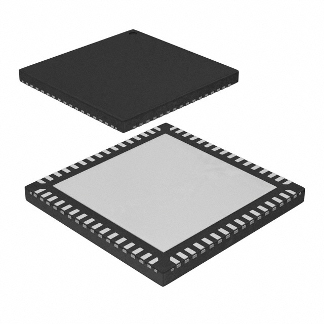
• 64-pin QFN package
• 133 MHz Link clock
• 48 MHz USB clock
Block Diagram
CPU
SRC
SATA
PCI
REF
LINK
DOT96
24_48M
48M
x2
x8
x1
x7
x3
x2
x1
x1
x1
PCIET [8:1]
PCIEC[8:1]
DOC[2:1]
FS[D:A]
VDD_SATA
SEL_P4_K8
PCIET0 /SATAT
PCIEC0 /SATAC
PLL2
PCIEX
Divider
Multiplexer
Controller
SEL[1:0]
PLL3
SATA
VDD_DOT
DOT96T/SATAT/LINK0
DOT96C/SATAC/LINK1
VDD_PCI
Divider
PCI[6:0]
XOUT
XIN
VSSREF
REF2/**MODE
REF1 /**FSC
PCI0/CLKREQ#B
**DOC1
PCI1/CLKREQ#A
VSSPCI
CPUT[1:0]
CPUC[1:0]
VDD_PCIEX
Divider
PCI2/**FSA
VDD_CPU
PC3/*FSB
PLL1
CPU
PCI5/*SEL0
REF[2:0]
PLL Reference
VDDPCI
14.318MHz
Crystal
PCI4/*SELP4_K8
VDD_REF
Xin
Xout
RESET_I#/ SRESET#
REF0/ **FSD
Pin Configuration
64 63 62 61 60 59 58 57 56 55 54 53 52 51 50 49
PCI6_F 1
VDD48 2
**SEL24_48 / 24_48M 3
**SEL1/48M 4
VSS48 5
VDDDOT 6
LINK0/DOT96T/SATAT 7
LINK1/DOT96C/SATAC 8
VSSDOT 9
VDDSATA 10
SATAT/PCIEXT0 11
SATAC/PCIEXC0 12
VSSSATA 13
PCIEXT1 14
PCIEXC1 15
VSSPCIE 16
48
47
46
45
44
43
42
41
40
39
38
37
36
35
34
33
CY28551
VDDREF
SCLK
SDATA
VTTPWRG#/PD
CPUT0
CPUC0
VDDCPU
CPUT1
CPUC1
VSSCPU
**DOC2
VSSA
VDDA
PCIEXT8/CPU_STP#
PCIEXC8/PCI_STP#
VDDPCIE
PCIEXT7
PCIEXC7
VSSPCIE
PCIEXT6
PCIEXC6
PCIEXT5
PCIEXC5
VDDPCIE
PCIEXC4
PCIEXT4
VSSPCIE
PCIEXC3
PCIEXT3
VDDPCIE
VDD_48
48M
Divider
PCIEXT2
PLL4
Fixed
PCIEXC2
17 18 19 20 21 22 23 24 25 26 27 28 29 30 31 32
TPWR_GD#/PD
24_48M
SEL24_48
RESET_I#
SDATA
SCLK
I2C
Logic
* Indicates internal pull up
** indicates internal pull down
WDT
SRESET#
....................... Document #: 001-05675 Rev. D Page 1 of 28
400 West Cesar Chavez, Austin, TX 78701
1+(512) 416-8500
1+(512) 416-9669
www.silabs.com
�CY28551
Pin Description
Pin No.
Name
Type
Description
1
PCI6_F
O
Free running 33 MHz clock output.
Intel Type-3A output buffer
2
VDD48
PWR
3
**SEL24_48#/24_4 I/O, PD 3.3V tolerant input for 24 MHz, 48 MHz selection/24_48MHz clock output. Internal
8M
150k pull down
1 = 24 MHz, 0 = 48 MHz
Intel Type-3A output buffer
4
**SEL1/48MHz
3.3V power supply for outputs.
I/O, PD 3.3V tolerant input for output selection/48MHz clock output. Refer to Table 1 for
selection options
Internal 150k pull down
5
VSS48
GND
Ground for outputs
6
VDDDOT
PWR
3.3V Power supply for outputs
7,8
LINK0/DOT96T/SA
O,
Link output for VIA and SIS, differential 96 MHz clock output and 100 MHz differential
TAT
SE/DiF clock. The output is selected by SEL[1:0]
LINK1/DOT96C/SA
TAC
9
VSSDOT
GND
Ground for outputs
10
VDDSATA
PWR
3.3V Power supply for outputs
11,12
PCIEX0[T/C]/SATA O, DIF Differential SRC clock output/Differential SATA SRC clock output
[T/C]
Intel Type-SR output buffer
13
VSSSATA
14,15
PCIEX[T/C]1
16
VSSPCIE
17,18
PCIEX[T/C]2
19
VDDPCIE
20,21
PCIEX[T/C]3
22
VSSPCIE
23,24
PCIEX[T/C]4
25
VDDPCIE
26,27,28,29
PCIEX[T/C][5:6]
30
VSSPCIE
31,32
PCIEX[T/C]7
GND
Ground for outputs
O, DIF 100 MHz Differential serial reference clock. Intel Type-SR output buffer
GND
Ground for outputs
O, DIF 100 MHz Differential serial reference clock. Intel Type-SR output buffer
PWR
3.3V power supply for outputs.
O, DIF 100 MHz Differential serial reference clock. Intel Type-SR output buffer
GND
Ground for outputs
O, DIF 100 MHz Differential serial reference clock. Intel Type-SR output buffer
PWR
3.3V power supply for outputs
O, DIF 100 MHz Differential Serial reference clock. Intel Type-SR output buffer
GND
Ground for outputs
O, DIF 100 MHz Differential Serial reference clock. Intel Type-SR output buffer
33
VDDPCIE
34,35
PCIEXT8/CPU_ST I/O, DIF
OP#
PCIEXC8/PCI_ST
OP#
3.3V-tolerant input for stopping PCI and SRC outputs/3.3V-tolerant input for
stopping CPU outputs/100-MHz Differential serial reference clocks.
The two multifunction pins are selected by MODE. Default PCIEX8
Intel Type-SR output buffer
36
VDDA
PWR
3.3V Power supply for PLL.
37
VSSA
GND
Ground for PLL.
38
**DOC2
I, PD
Dynamic Over Clocking pin
0 = normal, 1 = Frequency will be changed depend on DOC register. Internal 150k
pull-down.
GND
Ground for outputs.
39
VSSCPU
40,41
CPU[T/C]1
42
VDDCPU
43, 44
CPU[T/C]0
PWR
3.3V power supply for outputs
O, DIF Differential CPU clock output. Intel Type-SR output buffer.
PWR
3.3V Power supply for outputs+
O, DIF Differential CPU clock output. Intel Type-SR output buffer.
....................... Document #: 001-05675 Rev. D Page 2 of 28
�CY28551
Pin Description (continued)
Pin No.
45
Name
Type
Description
VTT_PWRGD#/PD
I
3.3V LVTTL input. This pin is a level-sensitive strobe used to latch the HW strapping
pin inputs. After asserting VTT_PWRGD# (active LOW), this pin becomes a
real-time input for asserting power-down (active HIGH).
46
SDATA
I/O
47
SCLK
I
SMBus compatible SCLOCK.
SMBus compatible SDATA
PWR
3.3V Power supply for outputs
48
VDDREF
49
XOUT
50
XIN
51
VSSREF
GND
52
REF2
O, SE 14.318 MHz REF clock output.
Intel Type-5 output buffer
53
**FSC/REF1
I/O,PD, 3.3V tolerant input for CPU frequency selection/14.318 MHz REF clock output
SE
Internal 150k pull down
Intel Type-5 output buffer
Refer to DC Electrical Specifications table for Vil_FS and Vih_FS specifications
54
**FSD/REF0
I/O,PD, 3.3V tolerant input for CPU frequency selection/14.318 MHz REF clock output
SE
Internal 150k pull down
Intel Type-5 output buffer
Refer to DC Electrical Specifications table for Vil_FS and Vih_FS specifications
55
RESET_I#/SRESE I/O, OD 3.3V tolerant input for reset all of registers to default setting
T#
3.3V LVTTL output for watchdog reset signal
56
**DOC1
57
PCI0/**CLKREQ#B I/O,SE, 33 MHz clock output/Output enable control for PCIEX4; 5 via I2C register
PD Default is PCI0
0 = Selected PCIEXs are enabled, 1 = Selected PCIEXs are disabled. Internal 150k
pull down
Intel Type-3A output buffer
58
PCI1/**CLKREQ#A I/O,SE, 33 MHz clock output/Output enable control for PCIEX6, 7via I2C register. Default is
PD PCI1
0 = Selected PCIEXs are enabled, 1 = Selected PCIEXs are disabled. Internal 150k
pull down
Intel Type-3A output buffer
59
VSSPCI
60
**FSA/PCI2
I/O, PD 3.3V tolerant input for CPU frequency selection/33 MHz clock output. Internal 150k
pull down
Intel Type-3A output buffer
Refer to DC Electrical Specifications table for Vil_FS and Vih_FS specifications
61
*FSB/PCI3
I/O, PU 3.3V tolerant input for CPU frequency selection/33 MHz clock output. Internal 150k
pull up
Intel Type-3A output buffer
Refer to DC Electrical Specifications table for Vil_FS and Vih_FS specifications
62
VDDPCI
63
*SELP4_K8/PCI3
I/O, PU 3.3V tolerant input for CPU clock output buffer type selection/33 MHz clock output.
Internal 150k pull up
Intel Type-3A output buffer
Refer to DC Electrical Specifications table for Vil_FS and Vih_FS specifications
0 = K8 CPU buffer type, 1 = P4 CPU buffer type.
64
*SEL0/PCI5
I/O, PU 3.3V tolerant input for output selection/33 MHz clock output. Refer to Table 1 for
selection options.
Internal 150k pull up
O
14.318 MHz Crystal Output
I
14.318 MHz Crystal Input
I, PD
GND
PWR
Ground for outputs
Dynamic Over Clocking pin
0 = normal; 1 = Frequency will be changed depend on DOC register. Internal 150k
pull-down
Ground for outputs.
3.3V power supply for outputs.
....................... Document #: 001-05675 Rev. D Page 3 of 28
�CY28551
Table 1. Frequency Select Table
FSD
FSC
FSB
FSA
FSEL3 FSEL2 FSEL1 FSEL0
Frequency Table (ROM)
CPU0
LINK
PCI
CPU VCO
0
0
0
0
266.6666667 266.6666667 100
66.6667
33.3333
800
80
60
200
800
30
60
200
0
0
0
1
133.3333333 133.3333333 100
66.6667
33.3333
800
40
60
200
800
30
60
200
0
0
1
0
100
66.6667
33.3333
800
60
60
200
800
30
60
200
0
0
1
1
166.6666667 166.6666667 100
66.6667
33.3333 666.6666667
60
63
175
800
30
60
200
0
1
0
0
333.3333333 333.3333333 100
66.6667
33.3333 666.6666667
120
63
175
800
30
60
200
0
1
0
1
100
100
100
66.6667
33.3333
800
30
60
200
800
30
60
200
0
1
1
0
400
400
100
66.6667
33.3333
800
120
60
200
800
30
60
200
0
1
1
1
200
250
100
66.6667
33.3333
1000
60
60
250
800
30
60
200
1
0
0
0
266.6666667 266.6666667 100 133.3333 33.3333
800
80
60
200
800
30
60
200
1
0
0
1
133.3333333 133.3333333 100 133.3333 33.3333
800
40
60
200
800
30
60
200
1
0
1
0
800
60
60
200
800
30
60
200
1
0
1
1
166.6666667 166.6666667 100 133.3333 33.3333 666.6666667
60
63
175
800
30
60
200
1
1
0
0
333.3333333 333.3333333 100 133.3333 33.3333 666.6666667
120
63
175
800
30
60
200
1
1
0
1
100
100
100 133.3333 33.3333
800
30
60
200
800
30
60
200
1
1
1
0
400
400
100 133.3333 33.3333
800
120
60
200
800
30
60
200
1
1
1
1
200
250
100 133.3333 33.3333
1000
60
60
250
800
30
60
200
200
200
CPU1
200
200
SRC
CPU PLL
Gear
SRC PLL
Constant CPU CPU PCIE
Gear
PCIE PCIE
(G)
M
N
VCO Constant M
N
100 133.3333 33.3333
Frequency Select Pins (FS[D:A])
To achieve host clock frequency selection, apply the appropriate logic levels to FS_A, FS_B, FS_C, and FS_D inputs
prior to VTT_PWRGD# assertion (as seen by the clock synthesizer). When VTT_PWRGD# is sampled LOW by the clock
chip (indicating processor VTT voltage is stable), the clock
chip samples the FS_A, FS_B, FS_C, and FS_D input values.
For all logic levels of FS_A, FS_B, FS_C, FS_D, and FS_E,
VTT_PWRGD# employs a one-shot functionality, in that once
a valid LOW on VTT_PWRGD# has been sampled, all further
VTT_PWRGD#, FS_A, FS_B, FS_C, and FS_D transitions will
be ignored, except in test mode.
Serial Data Interface
To enhance the flexibility and function of the clock synthesizer,
a two-signal serial interface is provided. Through the Serial
Data Interface, various device functions, such as individual
clock output buffers, can be individually enabled or disabled.
The registers associated with the Serial Data Interface
initialize to their default setting upon power-up, and therefore
use of this interface is optional. Clock device register changes
are normally made upon system initialization, if any are
required. The interface cannot be used during system
operation for power management functions.
Data Protocol
The clock driver serial protocol accepts byte write, byte read,
block write, and block read operations from the controller. For
block write/read operation, the bytes must be accessed in
sequential order from lowest to highest byte (most significant
bit first) with the ability to stop after any complete byte has
been transferred. For byte write and byte read operations, the
system controller can access individually indexed bytes. The
offset of the indexed byte is encoded in the command code,
as described in Table 2.
The block write and block read protocol is outlined in Table 3,
while Table 4 outlines the corresponding byte write and byte
read protocol. The slave receiver address is 11010010 (D2h).
Table 2. Command Code Definition
Bit
7
(6:0)
Description
0 = Block read or block write operation, 1 = Byte read or byte write operation
Byte offset for byte read or byte write operation. For block read or block write operations, these bits should be
'0000000'
....................... Document #: 001-05675 Rev. D Page 4 of 28
�CY28551
Table 3. Block Read and Block Write Protocol
Block Write Protocol
Bit
1
8:2
9
Description
Start
Block Read Protocol
Bit
1
Slave address – 7 bits
Write
8:2
9
Description
Start
Slave address – 7 bits
Write
10
Acknowledge from slave
10
Acknowledge from slave
18:11
Command Code – 8 bits
18:11
Command Code – 8 bits
19
Acknowledge from slave
19
Acknowledge from slave
Byte Count – 8 bits
(Skip this step if I2C_EN bit set)
20
Repeat start
27:20
28
36:29
37
45:38
Acknowledge from slave
27:21
Slave address – 7 bits
Data byte 1 – 8 bits
28
Read = 1
Acknowledge from slave
29
Acknowledge from slave
Data byte 2 – 8 bits
46
Acknowledge from slave
....
Data Byte/Slave Acknowledges
....
Data Byte N – 8 bits
....
Acknowledge from slave
....
Stop
37:30
38
46:39
47
55:48
56
Byte Count from slave – 8 bits
Acknowledge
Data byte 1 from slave – 8 bits
Acknowledge
Data byte 2 from slave – 8 bits
Acknowledge
....
Data bytes from slave/Acknowledge
....
Data Byte N from slave – 8 bits
....
NOT Acknowledge
....
Stop
Table 4. Byte Read and Byte Write Protocol
Byte Write Protocol
Bit
1
8:2
Description
Start
Slave address – 7 bits
Byte Read Protocol
Bit
1
8:2
Description
Start
Slave address – 7 bits
9
Write
9
Write
10
Acknowledge from slave
10
Acknowledge from slave
18:11
Command Code – 8 bits
18:11
Command Code – 8 bits
19
Acknowledge from slave
19
Acknowledge from slave
27:20
Data byte – 8 bits
28
Acknowledge from slave
29
Stop
....................... Document #: 001-05675 Rev. D Page 5 of 28
20
27:21
Repeated start
Slave address – 7 bits
28
Read
29
Acknowledge from slave
37:30
Data from slave – 8 bits
38
NOT Acknowledge
39
Stop
�CY28551
Control Registers
Byte 0: Control Register 0
Bit
@Pup
Type
Name
7
1
R/W
PCIEX[T/C]7
PCIEX[T/C]7 Output Enable
0 = Disable (Tri-state), 1 = Enable
Description
6
1
R/W
PCIEX[T/C]6
PCIEX[T/C]6 Output Enable
0 = Disable (Tri-state), 1 = Enable
5
1
R/W
PCIEX[T/C]5
PCIEX[T/C]5 Output Enable
0 = Disable (Tri-state), 1 = Enable
4
1
R/W
PCIEX[T/C]4
PCIEX[T/C]4 Output Enable
0 = Disable (Tri-state), 1 = Enable
3
1
R/W
PCIEX[T/C]3
PCIEX[T/C]3 Output Enable
0 = Disable (Tri-state), 1 = Enable
2
1
R/W
PCIEX[T/C]2
PCIEX[T/C]2 Output Enable
0 = Disable (Tri-state), 1 = Enable
1
1
R/W
PCIEX[T/C]1
PCIEX[T/C]1 Output Enable
0 = Disable (Tri-state), 1 = Enable
0
1
R/W
SATA/PCIEX[T/C]0 SATA/PCIEX[T/C]0 Output Enable
0 = Disable (Tri-state), 1 = Enable
Byte 1: Control Register 1
Bit
@Pup
Type
Name
Description
7
1
R/W
SATA/DOT96]
6
1
R/W
24_48M
24_48M Output Enable
0 = Disable, 1 = Enable
5
1
R/W
48M
48M Output Enable
0 = Disable, 1 = Enable
4
1
R/W
REF2
REF2 Output Enable
0 = Disable, 1 = Enable
3
1
R/W
REF1
REF1 Output Enable
0 = Disable, 1 = Enable
2
1
R/W
REF0
REF0 Output Enable
0 = Disable, 1 = Enable
1
1
R/W
CPU[T/C]1
CPU[T/C]1 Output Enable
0 = Disable (Tri-state), 1 = Enable
0
1
R/W
CPU[T/C]0
CPU[T/C]0 Output Enable
0 = Disable (Tri-state), 1 = Enable
SATA/DOT96Output Enable
0 = Disable (Tri-state), 1 = Enable
Byte 2: Control Register 2
Bit
@Pup
Type
Name
Description
7
1
R/W
Reserved
6
1
R/W
PCI6_F
PCI6_F Output Enable
0 = Disable, 1 = Enable
5
1
R/W
PCI5
PCI5 Output Enable
0 = Disable, 1 = Enable
4
1
R/W
PCI4
PCI4 Output Enable
0 = Disable, 1 = Enable
3
1
R/W
PCI3
PCI3 Output Enable
0 = Disable, 1 = Enable
Reserved
....................... Document #: 001-05675 Rev. D Page 6 of 28
�CY28551
Byte 2: Control Register 2 (continued)
Bit
@Pup
Type
Name
Description
2
1
R/W
PCI2
PCI2 Output Enable
0 = Disable, 1 = Enable
1
1
R/W
PCI1
PCI1 Output Enable
0 = Disable, 1 = Enable
0
1
R/W
PCI0
PCI0 Output Enable
0 = Disable, 1 = Enable
Byte 3: Control Register 3
Bit
@Pup
Type
Name
Description
7
1
R/W
LINK1
LINK1 Output Enable
0 = Disable, 1 = Enable
6
1
R/W
LINK0
LINKI0 Output Enable
0 = Disable, 1 = Enable
5
1
R/W
PCIEX[T/C]8
4
1
R/W
Reserved
Reserved
3
0
R/W
Reserved
Reserved
2
1
R/W
PCI
33 MHz Output Drive Strength
0 = 2x, 1 = 1x
1
1
R/W
REF
REF Output Drive Strength
0 = 2x, 1 = 1x
0
0
R/W
48M, 24_48M
PCIEX[T/C]8 Output Enable
0 = Disable (Tri-state), 1 = Enable
48 MHz and 24_48M Output Drive Strength
0 = 2x, 1 = 1x
Byte 4: Control Register 4
Bit
@Pup
Type
Name
7
0
R/W
CPU1
Allow control of CPU1 with assertion of CPU_STP#
0 = Free Running
1 = Stopped with CPU_STP#
Description
6
0
R/W
CPU0
Allow control of CPU0 with assertion of CPU_STP#
0 = Free Running
1 = Stopped with CPU_STP#
5
0
R/W
PCI6_F
Allow control of PCI6_F with assertion of PCI_STP#
0 = Free Running
1 = Stopped with PCI_STP#
4
0
R/W
PCIEX
Allow control of PCIEX with assertion of PCI_STP#
0 = Free Running
1 = Stopped with PCI_STP#
3
0
R/W
FSEL_D
2
0
R/W
FSEL_C
1
0
R/W
FSEL_B
0
0
R/W
FSEL_A
SW Frequency selection bits. See Table 1.
....................... Document #: 001-05675 Rev. D Page 7 of 28
�CY28551
Byte 5: Control Register 5
Bit
@Pup
Type
Name
7
0
R/W
CPU_SS1
Description
6
0
R/W
CPU_SS0
5
0
R/W
CPU_SS_OFF
4
0
R/W
PCIE_SS0
3
0
R/W
PCIE_SS_OFF
PLL2 (PCIEPLL) Spread Spectrum Enable
0 = SRC spread off, 1 = SRC spread on
2
0
R/W
SATA_SS_OFF
PLL3 (SATAPLL) Spread Spectrum Enable
0 = Spread off, 1 = Spread on
1
HW
R/W
SEL24_48
24M/48 MHz output selection
0 = 48 MHz, 1 = 24 MHz
0
1
R/W
Reserved
Reserved
CPU (PLL1) Spread Spectrum Selection
00: –0.5% (peak to peak)
01: ±0.25% (peak to peak)
10: –1.0% (peak to peak)
11: ±0.5% (peak to peak)
PLL1 (CPUPLL) Spread Spectrum Enable
0 = Spread off, 1 = Spread on
PLL2 (PCIEPLL) Spread Spectrum Selection
0: –0.5% (peak to peak)
0: –1.0% (peak to peak)
Byte 6: Control Register 6
Bit
@Pup
Type
Name
Description
7
0
R/W
SW_RESET
Software Reset.
When set, the device asserts a reset signal on SRESET# upon completion
of the block/word/byte write that set it. After asserting and deasserting the
SRESET# this bit will self clear (set to 0).
6
0
R/W
Reserved
5
0
R/W
FIX_LINK_PCI
4
HW
R
FSD
FSD Reflects the value of the FSD pin sampled on power up. 0 = FSD was
low during VTT_PWRGD# assertion.
3
HW
R
FSC
FSC Reflects the value of the FSC pin sampled on power up. 0 = FSC was
low during VTT_PWRGD# assertion.
2
HW
R
FSB
FSB Reflects the value of the FSB pin sampled on power up. 0 = FSB was
LOW during VTT_PWRGD# assertion
1
HW
R
FSA
FSA Reflects the value of the FSA pin sampled on power up. 0 = FSA was
LOW during VTT_PWRGD# assertion
0
HW
R
POWERGOOD
Name
Reserved
LINK and PCI clock source selection
0 = PLL2(SRCPLL), 1 = PLL (SATAPLL)
Power Status bit:
0 = Internal power or Internal resets are NOT valid
1 = Internal power and Internal resets are valid
Read only Bit 7 sets to 0 when Bit 7 = 0
Byte 7: Vendor ID
Bit
@Pup
Type
Description
7
0
R
Revision Code Bit 3 Revision Code Bit 3
6
0
R
Revision Code Bit 2 Revision Code Bit 2
5
1
R
Revision Code Bit 1 Revision Code Bit 1
4
0
R
Revision Code Bit 0 Revision Code Bit 0
3
1
R
Vendor ID Bit 3
Vendor ID Bit 3
2
0
R
Vendor ID Bit 2
Vendor ID Bit 2
....................... Document #: 001-05675 Rev. D Page 8 of 28
�CY28551
Byte 7: Vendor ID (continued)
Bit
@Pup
Type
Name
Description
1
0
R
Vendor ID Bit 1
Vendor ID Bit 1
0
0
R
Vendor ID Bit 0
Vendor ID Bit 0
Byte 8: Control Register 8
Bit
@Pup
Type
Name
Description
7
0
R/W
CR1_PCIEX7
PCIEX[T/C75 CLKREQ#A Control
1 = PCIEX [T/C]5 stoppable by CLKREQ#B pin
0 = Free running
6
0
R/W
CR1_PCIEX6
PCIEX[T/C]6 CLKREQ#A Control
1 = PCIEX [T/C]4 stoppable by CLKREQ#B pin
0 = Free running
5
0
R/W
CR1_PCIEX5
PCIEX[T/C]5 CLKREQ#B Control
1 = PCIEX [T/C]5 stoppable by CLKREQ#B pin
0 = Free running
4
0
R/W
CR1_PCIEX4
PCIEX[T/C]4 CLKREQ#B Control
1 = PCIEX [T/C]4 stoppable by CLKREQ#B pin
0 = Free running
3
0
R/W
RESERVED
RESERVED, Set = 0
2
0
R/W
RESERVED
RESERVED, Set = 0
1
0
R/W
RESERVED
RESERVED, Set = 0
0
0
R/W
RESERVED
RESERVED, Set = 0
Byte 9: Control Register 9
Bit
@Pup
Type
Name
7
0
R/W
DF3_N8
The DF3_N[8:0] configures CPU frequency for Dynamic Frequency.
DOC[1:2] =11
Description
6
0
R/W
DF2_N8
The DF2_N[8:0] configures CPU frequency for Dynamic Frequency.
DOC[1:2] =10
5
0
R/W
DF1_N8
The DF1_N[8:0] configures CPU frequency for Dynamic Frequency.
DOC[1:2] =01
4
0
R/W
RESERVED
RESERVED, Set = 0
3
0
R/W
RESERVED
RESERVED, Set = 0
2
1
R/W
SMSW_Bypass
1
0
R/W
SMSW_SEL
Smooth switch select
0 = Select CPU_PLL
1 = Select SRC_PLL
0
0
R/W
RESERVED
RESERVED, Set = 0
Smooth switch Bypass
0 = Activate SMSW block
1 = Bypass and deactivate SMSW block.
....................... Document #: 001-05675 Rev. D Page 9 of 28
�CY28551
Byte 10: Control Register 10
Bit
@Pup
Type
Name
7
0
R/W
DF1_N7
6
0
R/W
DF1_N6
5
0
R/W
DF1_N5
4
0
R/W
DF1_N4
3
0
R/W
DF1_N3
2
0
R/W
DF1_N2
1
0
R/W
DF1_N1
0
0
R/W
DF1_N0
Description
The DF1_N[8:0] configures CPU frequency for Dynamic Frequency.
DOC[1:2] =01.
Byte 11: Control Register 11
Bit
@Pup
Type
Name
7
0
R/W
DF2_N7
6
0
R/W
DF2_N6
5
0
R/W
DF2_N5
4
0
R/W
DF2_N4
3
0
R/W
DF2_N3
2
0
R/W
DF2_N2
1
0
R/W
DF2_N1
0
0
R/W
DF2_N0
Description
The DF2_N[8:0] configures CPU frequency for Dynamic Frequency.
DOC[1:2] =10
Byte 12: Control Register 12
Bit
@Pup
Type
Name
7
0
R/W
DF3_N7
6
0
R/W
DF3_N6
5
0
R/W
DF3_N5
4
0
R/W
DF3_N4
3
0
R/W
DF3_N3
2
0
R/W
DF3_N2
1
0
R/W
DF3_N1
0
0
R/W
DF3_N0
Description
The DF3_N[8:0] configures CPU frequency for Dynamic Frequency.
DOC[1:2] =11
Byte 13: Control Register 13
Bit
@Pup
Type
Name
Description
7
0
R/W
6
0
R/W
Timer_SEL
Timer_SEL selects the WD reset function at SRESET pin when WD times
out.
0 = Reset and Reload Recovery_Frequency
1 = Only Reset
5
1
R/W
Time_Scale
Time_Scale allows selection of WD time scale
0 = 294 ms, 1 = 2.34 s
Recovery_Frequency This bit allows selection of the frequency setting to which the clock will be
restored once the system is rebooted
0 = Use HW settings 1 = Recovery N[8:0]
..................... Document #: 001-05675 Rev. D Page 10 of 28
�CY28551
Byte 13: Control Register 13
Bit
@Pup
Type
Name
Description
4
0
R/W
WD_Alarm
WD_Alarm is set to ‘1’ when the watchdog times out. It is reset to ‘0’ when
the system clears the WD_TIMER time stamp
3
0
R/W
WD_TIMER2
2
0
R/W
WD_TIMER1
1
0
R/W
WD_TIMER0
0
0
R/W
WD_EN
Watchdog timer time stamp selection
000: Reserved (test mode)
001: 1 * Time_Scale
010: 2 * Time_Scale
011: 3 * Time_Scale
100: 4 * Time_Scale
101: 5 * Time_Scale
110: 6 * Time_Scale
111: 7 * Time_Scale
Watchdog timer enable. When the bit is asserted, Watchdog timer is
triggered and time stamp of WD_Timer is loaded
0 = Disable, 1 = Enable
Byte 14: Control Register 14
Bit
@Pup
Type
Name
Description
7
0
R/W
CPU_DAF_N7
6
0
R/W
CPU_DAF_N6
5
0
R/W
CPU_DAF_N5
4
0
R/W
CPU_DAF_N4
3
0
R/W
CPU_DAF_N3
If Prog_CPU_EN is set, the values programmed in CPU_DAF_N[8:0] and
CPU_DAF_M[6:0] will be used to determine the CPU output frequency.
The setting of the FS_Override bit determines the frequency ratio for CPU
and other output clocks. When it is cleared, the same frequency ratio
stated in the Latched FS[E:A] register will be used. When it is set, the
frequency ratio stated in the FSEL[3:0] register will be used
2
0
R/W
CPU_DAF_N2
1
0
R/W
CPU_DAF_N1
0
0
R/W
CPU_DAF_N0
Byte 15: Control Register 15
Bit
@Pup
Type
Name
Description
7
0
R/W
CPU_DAF_N8
6
0
R/W
CPU_DAF_M6
5
0
R/W
CPU_DAF_M5
4
0
R/W
CPU_DAF_M4
3
0
R/W
CPU_DAF_M3
If Prog_CPU_EN is set, the values programmed in CPU_DAF_N[8:0] and
CPU_DAF_M[6:0] will be used to determine the CPU output frequency.
The setting of the FS_Override bit determines the frequency ratio for CPU
and other output clocks. When it is cleared, the same frequency ratio
stated in the Latched FS[E:A] register will be used. When it is set, the
frequency ratio stated in the FSEL[3:0] register will be used.
2
0
R/W
CPU_DAF_M2
1
0
R/W
CPU_DAF_M1
0
0
R/W
CPU_DAF_M0
..................... Document #: 001-05675 Rev. D Page 11 of 28
�CY28551
Byte 16: Control Register 16
Bit
@Pup
Type
Name
7
0
R/W
PCIE_DAF_N7
6
0
R/W
PCIE_DAF_N6
5
0
R/W
PCIE_DAF_N5
4
0
R/W
PCIE_DAF_N4
3
0
R/W
PCIE_DAF_N3
2
0
R/W
PCIE_DAF_N2
1
0
R/W
PCIE_DAF_N1
0
0
R/W
PCIE_DAF_N0
Description
The PCIE_DAF_N[8:0] configures the PCIE frequency for
Dial-A-Frequency
Byte 17: Control Register 17
Bit
@Pup
Type
Name
7
0
R/W
Recovery N7
Watchdog Recovery Bit
Description
6
0
R/W
Recovery N6
Watchdog Recovery Bit
5
0
R/W
Recovery N5
Watchdog Recovery Bit
4
0
R/W
Recovery N4
Watchdog Recovery Bit
3
0
R/W
Recovery N3
Watchdog Recovery Bit
2
0
R/W
Recovery N2
Watchdog Recovery Bit
1
0
R/W
Recovery N1
Watchdog Recovery Bit
0
0
R/W
Recovery N0
Watchdog Recovery Bit
Byte 18: Control Register 18
Bit
@Pup
Type
Name
Description
7
0
R/W
PCIE_N8
6
0
R/W
FS[D:A]
FS_Override
0 = Select operating frequency by FS(D:A) input pins
1 = Select operating frequency by FSEL_(3:0) settings
PCI-E Dial-A-Frequency Bit N8
5
0
R/W
DF_EN
Dynamic Frequency for CPU Frequency Enable
0 = Disable, 1 = Enable
4
0
R/W
RESET_I_EN
3
0
R/W
Prog_PCIE_EN
Programmable SRC Frequency Enable
0 = Disable, 1 = Enabled
2
0
R/W
Prog_CPU_EN
Programmable CPU Frequency Enable
0 = Disable, 1 = Enable
1
0
R/W
Watchdog
Autorecovery
Watchdog Autorecovery Mode
0 = Disable (Manual), 1= Enable (Auto)
0
0
R/W
Recovery N8
Watchdog Recovery Bit
RESET_I# Enable
0 = Disable, 1 = Enable
Table 5. Crystal Recommendations
Frequency
(Fund)
Cut
Loading Load Cap
Drive
(max.)
Shunt Cap
(max.)
Motional
(max.)
Tolerance
(max.)
Stability
(max.)
Aging
(max.)
14.31818 MHz
AT
Parallel
0.1 mW
5 pF
0.016 pF
35 ppm
30 ppm
5 ppm
20 pF
..................... Document #: 001-05675 Rev. D Page 12 of 28
�CY28551
Crystal Recommendations
The CY28551 requires a parallel resonance crystal. Substituting a series resonance crystal will cause the CY28551 to
operate at the wrong frequency and violate the ppm specification. For most applications there is a 300-ppm frequency
shift between series and parallel crystals due to incorrect
loading.
Clock Chip
Ci2
Ci1
Pin
3 to 6p
Crystal Loading
Crystal loading plays a critical role in achieving low ppm performance. To realize low ppm performance, the total capacitance
the crystal will see must be considered to calculate the appropriate capacitive loading (CL).
X2
X1
Cs1
Cs2
Trace
2.8 pF
XTAL
Figure 1 shows a typical crystal configuration using the two
trim capacitors. An important clarification for the following
discussion is that the trim capacitors are in series with the
crystal not parallel. It is a common misconception that load
capacitors are in parallel with the crystal and should be
approximately equal to the load capacitance of the crystal.
This is not true.
Ce1
Ce2
Trim
33 pF
Figure 2. Crystal Loading Example
Use the following formulas to calculate the trim capacitor
values for Ce1 and Ce2.
Load Capacitance (each side)
Ce = 2 * CL – (Cs + Ci)
Total Capacitance (as seen by the crystal)
CLe
=
1
1
( Ce1 + Cs1
+ Ci1 +
1
Ce2 + Cs2 + Ci2
)
Figure 1. Crystal Capacitive Clarification
CL....................................................Crystal load capacitance
Calculating Load Capacitors
In addition to the standard external trim capacitors, trace
capacitance and pin capacitance must also be considered to
correctly calculate crystal loading. As mentioned previously,
the capacitance on each side of the crystal is in series with the
crystal. This means the total capacitance on each side of the
crystal must be twice the specified crystal load capacitance
(CL). While the capacitance on each side of the crystal is in
series with the crystal, trim capacitors (Ce1,Ce2) should be
calculated to provide equal capacitive loading on both sides.
..................... Document #: 001-05675 Rev. D Page 13 of 28
CLe......................................... Actual loading seen by crystal
using standard value trim capacitors
Ce..................................................... External trim capacitors
Cs .............................................. Stray capacitance (terraced)
Ci ...........................................................Internal capacitance
(lead frame, bond wires etc.)
Multifunction Pin Selection
In the CY28551, some of the pins can provide different types
of frequency, depending on the SEL[1:0] HW strapping pin
setting, to support different chipset vendors. The configuration
is shown as follows:
SEL[1:0]
LINK/DOT/SA
TA
00
LINK
SATA
SIS
01
DOT
SATA
Intel W/Gfx
10
LINK
PCIEX
VIA
11
SATA
PCIEX
Intel
SATA/PCIE
Platform
�CY28551
Dynamic Frequency
Dynamic Frequency – Dynamic Frequency (DF) is a technique
used to increase CPU frequency or SRC frequency dynamically from any starting value. The user selects the starting
point, either by HW, FSEL, or DAF, then enables DF. After that,
DF will dynamically change as determined by DF-N registers
and the M value of frequency table.
DF Pin – There are two pins to be used on Dynamic Frequency
(DF). When used as DF, these two pins will map to four DF-N
registers that correspond to different “N” values for Dynamic
Frequency. Any time there is a change in DF, it should load the
new value.
DOC[2:1]
DOC N register
00
Original Frequency
01
DF1_N
10
DF2_N
11
DF3_N
SRC_DAF Enable – This bit enables SRC DAF mode. By
default, it is not set. When set, the operating frequency is
determined by the values entered into the SRC_DAF_N
register. Note: The SRC_DAF_N register must contain valid
values before SRC_DAF is set. Default = 0, (No DAF).
SRC_DAF_N – There are nine bits (for 512 values) to linearly
change the CPU frequency (limited by VCO range). Default =
0, (0000). The allowable values for N are detailed in the
frequency select table (Table 1).
Recovery – The recovery mechanism during CPU DAF, when
the system locks up and the watchdog timer is enabled, is
determined by the “Watchdog Recovery Mode” and
“Watchdog Autorecovery Enable” bits. The possible recovery
methods are: (A) Auto, (B) Manual (by Recovery N), (C) HW,
and (D) No recovery, just send reset signal.
There is no recovery mode for SRC Dial-a-Frequency.
Software Frequency Select
This mode allows the user to select the CPU output
frequencies using the Software Frequency select bits in the
SMBUS register.
DF_EN bit – This bit enables the DF mode. By default, it is not
set. When set, the operating frequency is determined by
DF[2:0] pins. Default = 0, (No DF)
FSEL – There are four bits (for 16 combinations) to select
predetermined CPU frequencies from a table. The table selections are detailed in Table 1.
Dial-A-Frequency (CPU & PCIEX)
FS_Override – This bit allows the CPU frequency to be
selected from HW or FSEL settings. By default, this bit is not
set and the CPU frequency is selected by HW. When this bit
is set, the CPU frequency is selected by the FSEL bits. Default
= 0.
This feature allows users to overclock their systems by slowly
stepping up the CPU or SRC frequency. When the programmable output frequency feature is enabled, the CPU and SRC
frequencies are determined by the following equation:
Fcpu = G * N/M or Fcpu = G2 * N, where G2 = G/M.
‘N’ and ‘M’ are the values programmed in Programmable
Frequency Select N-Value Register and M-Value Register,
respectively. ‘G’ stands for the PLL Gear Constant, which is
determined by the programmed value of FS[E:A]. See Table 1
for the Gear Constant for each Frequency selection. The PCI
Express only allows user control of the N register; the M value
is fixed and documented in Table 1.
In this mode, the user writes the desired N and M value into
the DAF I2C registers. The user cannot change only the M
value and must change both the M and the N values at the
same time, if they require a change to the M value. The user
may change only the N value if required.
Associated Register Bits
CPU_DAF Enable – This bit enables CPU DAF mode. By
default, it is not set. When set, the operating frequency is
determined by the values entered into the CPU_DAF_N
register. Note: The CPU_DAF_N and M register must contain
valid values before CPU_DAF is set. Default = 0, (No DAF).
CPU_DAF_N – There are nine bits (for 512 values) to linearly
change the CPU frequency (limited by VCO range). Default =
0, (0000). The allowable values for N are detailed in the
frequency select table (Table 1).
CPU_DAF_M – There are 7 bits (for 128 values) to linearly
change the CPU frequency (limited by VCO range). Default =
0. The allowable values for M are detailed in the frequency
select table (Table 1).
..................... Document #: 001-05675 Rev. D Page 14 of 28
Recovery – The recovery mechanism during FSEL when the
system locks up is determined by the “Watchdog Recovery
Mode” and “Watchdog Autorecovery Enable” bits. The only
possible recovery method is to use Hardware Settings. Auto
recovery or manual recovery can cause a wrong output
frequency because the output divider may have changed with
the selected CPU frequency and these recovery methods will
not recover the original output divider setting.
Smooth Switching
The device contains one smooth switch circuit, which is shared
by the CPU PLL and SRC PLL. The smooth switch circuit
ensures that when the output frequency changes by
overclocking, the transition from the old frequency to the new
frequency is a slow, smooth transition containing no glitches.
The rate of change of output frequency when using the smooth
switch circuit is less than 1 MHz/0.667 s. The frequency
overshoot and undershoot will be less than 2%.
The smooth switch circuit can be assigned auto or manual
mode. In auto mode, the clock generator will assign smooth
switch automatically when the PLL will perform overclocking.
For manual mode, the smooth switch circuit can be assigned
to either PLL via SMBUS. By default the smooth switch circuit
is set to auto mode. Either PLL can still be overclocked when
it does not have control of the smooth switch circuit, but it is
not guaranteed to transition to the new frequency without large
frequency glitches.
Do not enable overclocking and change the N values of both
PLLs in the same SMBUS block write and use smooth switch
mechanism on spread spectrum on/off.
�CY28551
Watchdog Timer
“Watchdog Recovery Register” will be used for recovery.
Default = 1, Autorecovery.
The Watchdog timer is used in the system in conjunction with
overclocking. It is used to provide a reset to a system that has
hung up due to overclocking the CPU and the Front side bus.
The watchdog is enabled by the user and if the system
completes its checkpoints, the system will clear the timer.
However, when the timer runs out, there will be a reset pulse
generated on the SRESET# pin for 20 ms that is used to reset
the system.
Watchdog Recovery Register – This is a nine-bit register to
store the watchdog N recovery value. This value can be written
by the Autorecovery or User depending on the state of the
“Watchdog Autorecovery Enable bit”.
When the Watchdog is enabled (WD_EN = 1) the Watchdog
timer will start counting down from a value of Watchdog_timer
* time scale. If the Watchdog timer reaches 0 before the
WD_EN bit is cleared then it will assert the SRESET# signal
and set the Watchdog Alarm bit to ‘1’.
To use the watchdog, the SRESET# pin must be enabled by
sampling SRESET_EN pin LOW by VTTPWRGD# assertion
during system boot up.
If at any point during the Watchdog timer countdown the time
stamp or Watchdog timer bits are changed, the timer will reset
and start counting down from the new value.
After the Reset pulse, the watchdog will stay inactive until
either:
1. A new time stamp or watchdog timer value is loaded.
2. The WD_EN bit is cleared and then set again.
Watchdog Register Bits
The following register bits are associated with the Watchdog
timer:
Watchdog Enable – This bit (by default) is not set, which
disables the Watchdog. When set, the Watchdog is enabled.
Also, when there is a transition from LOW to HIGH, the timer
reloads. Default = 0, disable
Watchdog Timer – There are three bits (for seven combinations) to select the timer value. Default = 000, the value '000'
is a reserved test mode.
Watchdog Alarm – This bit is a flag and when it is set, it
indicates that the timer has expired. This bit is not set by
default. When the bit is set, the user is allowed to clear. Default
= 0.
Watchdog Time Scale – This bit selects the multiplier. When
this bit is not set, the multiplier will be 250 ms. When set (by
default), the multiplier will be 3s. Default = 1
Watchdog Reset Mode – This selects the Watchdog Reset
Mode. When this bit is not set (by default), the Watchdog will
send a reset pulse and reload the recovery frequency
depending on the Watchdog Recovery Mode setting. When
set, it sends a reset pulse. Default = 0, Reset & Recover
Frequency.
Watchdog Recovery Mode – This bit selects the location to
recover from. One option is to recover from the HW settings
(already stored in SMBUS registers for readback capability)
and the second is to recover from a register called “Recovery
N”. Default = 0 (Recover from the HW setting)
Watchdog Autorecovery Enable – This bit is set by default and
the recovered values are automatically written into the
“Watchdog Recovery Register” and reloaded by the Watchdog
function. When this bit is not set, the user is allowed to write to
the “Watchdog Recovery Register”. The value stored in the
..................... Document #: 001-05675 Rev. D Page 15 of 28
Watchdog Recovery Modes
There are three operating modes that require Watchdog
recovery. The modes are Dial-A-Frequency (DAF), Dynamic
Clocking (DF), or Frequency Select. There are four different
recovery modes; the following sections list the operating mode
and the recovery mode associated with it.
Recover to Hardware M, N, O
When this recovery mode is selected, in the event of a
Watchdog timeout, the original M, N, and O values that were
latched by the HW FSEL pins at chip boot-up will be reloaded.
Autorecovery
When this recovery mode is selected, in the event of a
Watchdog timeout, the M and N values stored in the Recovery
M and N registers will be reloaded. The current values of M
and N will be latched into the internal recovery M and N
registers by the WD_EN bit being set.
Manual Recovery
When this recovery mode is selected, in the event of a
Watchdog timeout, the N value as programmed by the user in
the N recovery register, and the M value that is stored in the
Recovery M register (not accessible by the user), will be
restored. The current M value will be latched to M recovery
register by the WD_EN bit being set.
No Recovery
If no recovery mode is selected, in the event of a Watchdog
time out, the device will assert the SRESET# and keep the
current values of M and N
Software Reset
Software reset is a reset function that is used to send out a
pulse from the SRESET# pin. It is controlled by the
SW_RESET enable register bit. Upon completion of the
byte/word/block write in which the SW_RESET bit was set, the
device will send a RESET pulse on the SRESET# pin. The
duration of the SRESET# pulse will be the same as the
duration of the SRESET# pulse after a Watchdog timer time
out.
After the SRESET# pulse is asserted the SW_RESET bit will
be automatically cleared by the device.
PD Clarification
The VTT_PWRGD#/PD pin is a dual-function pin. During initial
power up, the pin functions as VTT_PWRGD#. Once
VTT_PWRGD# has been sampled low by the clock chip, the
pin assumes PD functionality. The PD pin is an asynchronous
active HIGH input used to shut off all clocks cleanly prior to
shutting off power to the device. This signal must be synchronized internal to the device prior to powering down the clock
synthesizer. PD is also an asynchronous input for powering up
the system. When PD is asserted HIGH, all clocks must be
�CY28551
driven to a LOW value and held prior to turning off the VCOs
and the crystal oscillator
state, PD must be asserted HIGH in less than 10 s after
asserting VTT_PWRGD#.
PD Assertion
PD Deassertion
When PD is sampled HIGH by two consecutive rising edges
of CPUC, all single-ended outputs must be held LOW on their
next HIGH-to-LOW transition and differential clocks must be
held HIGH or tri-stated (depending on the state of the control
register drive mode bit) on the next “Diff clock#” HIGH-to-LOW
transition within 4 clock periods. When the SMBus PD drive
mode bit corresponding to the differential (CPU, SRC, and
DOT) clock output of interest is programmed to '0', the clock
output must be held with “Diff clock” pin driven HIGH at 2 x Iref,
and “Diff clock#” tri-state. If the control register PD drive mode
bit corresponding to the output of interest is programmed to ‘1’,
then both the “Diff clock” and the “Diff clock#” are tri-state. Note
Figure 3 shows CPUT = 133 MHz and PD drive mode = '1' for
all differential outputs. This diagram and description is applicable to valid CPU frequencies 100, 133, 166, and 200 MHz.
In the event that PD mode is desired as the initial power-on
The power-up latency must be less than 1.8 ms. This is the
time from the deassertion of the PD pin or the ramping of the
power supply until the time that stable clocks are output from
the clock chip. All differential outputs stopped in a tri-state
condition resulting from power down must be driven HIGH in
less than 300 s of PD deassertion to a voltage greater than
200 mV. After the clock chip's internal PLL is powered up and
locked, all outputs are to be enabled within a few clock cycles
of each other. Figure 4 is an example showing the relationship
of clocks coming up. Unfortunately, we can not show all
possible combinations; designers need to ensure that from the
first active clock output to the last takes no more than two full
PCI clock cycles.
PD
C PUT, 133 M H z
C PUC , 133 M H z
SR CT 100 M H z
SR CC 100 M H z
L IN K
U SB, 48 M H z
D O T96T
D O T96C
P C I, 3 3 M H z
REF
Figure 3. PD Assertion Timing Waveform
T s t a b le
< 1 .8 m s
PD
C PU T, 133 M H z
C PU C , 133 M H z
SR C T 100 M H z
SR C C 100 M H z
L IN K
U SB, 48 M H z
DO T96T
DO T96C
P C I, 3 3 M H z
REF
T d r iv e _ P W R D N #
200 m V
Figure 4. PD Deassertion Timing Waveform
..................... Document #: 001-05675 Rev. D Page 16 of 28
�CY28551
CPU_STP# Clarification
The CPU_STP# signal is an active LOW input used for cleanly
stopping and starting the CPU outputs while the rest of the
clock generator continues to function. Note that the assertion
and deassertion of this signal is absolutely asynchronous.
CPU_STP# Assertion
while the rest of the clock generator continues to function.
When the CPU_STP# pin is asserted, all CPU outputs that are
set with the SMBus configuration to be stoppable via assertion
of CPU_STP# will be stopped after being sampled by 2 to 6
rising edges of the internal CPUC clock. The final state of the
stopped CPU clock is LOW due to tri-state; both CPUT and
CPUC outputs will not be driven.
The CPU_STP# signal is an active LOW input used for
synchronous stopping and starting of the CPU output clocks
CPU_STP#
CPUT
CPUC
Figure 5. CPU_STP# Assertion Timing Waveform
C PU _STP#
CPUT
CPUC
C P U T In t e r n a l
C P U C In t e r n a l
T d r iv e _ C P U _ S T P # , 1 0 n S > 2 0 0 m V
Figure 6. CPU_STP# Deassertion
CPU_STP# Deassertion
The deassertion of the CPU_STP# signal will cause all CPU
outputs that were stopped to resume normal operation in a
synchronous manner, synchronous manner meaning that no
short or stretched clock pulses will be produced when the
clock resumes. The maximum latency from the deassertion to
active outputs is between 2 and 6 CPU clock periods (2 clocks
are shown). If the control register tri-state bit corresponding to
the output of interest is programmed to '1', then the stopped
CPU outputs will be driven HIGH within 10 ns of CPU_Stop#
deassertion to a voltage greater than 200 mV.
PCI_STP# Clarification
The PCI_STP# signal is an active LOW input used for cleanly
stopping and starting the PCI and PCIEX outputs while the rest
of the clock generator continues to function. The PCIF and
PCIEX clocks are special in that they can be programmed to
ignore PCI_STP# by setting the register bit corresponding to
the output of interest to free running. Outputs set to free
running will ignore the PCI_STP# pin.
PCI_STP# Assertion
The impact of asserting the PCI_STP# signal is as follows. The
clock chip is to sample the PCI_STP# signal on a rising edge
..................... Document #: 001-05675 Rev. D Page 17 of 28
of PCIF clock. After detecting the PCI_STP# assertion LOW,
all PCI and stoppable PCIF clocks will latch LOW on their next
HIGH-to-LOW transition. After the PCI clocks are latched
LOW, the stoppable PCIEX clocks will latch to LOW due to
tri-state, as shown in Figure 7. The one PCI clock latency
shown is critical to system functionality; any violation of this
may result in system failure. The Tsu_pci_stp# is the setup
time required by the clock generator to correctly sample the
PCI_STP# assertion. This time is 10 ns minimum.
PCI_STP# Deassertion
The deassertion of the PCI_STP# signal functions as follows.
The deassertion of the PCI_STP# signal is to be sampled on
the rising edge of the PCIF free running clock domain. After
detecting PCI_STP# deassertion, all PCI, stoppable PCIF and
stoppable PCIEX clocks will resume in a glitch-free manner.
The PCI and PCIEX clock resume latency should exactly
match the 1 PCI clock latency required for PCI_STP# entry.
The stoppable PCIEX clocks must be driven HIGH within
15 ns of PCI_STP# deassertion. Figure 8 shows the appropriate relationship. The Tsu_cpu_stp# is the setup time
required by the clock generator to correctly sample the
PCI_STP# deassertion. This time is 10 ns minimum.
�CY28551
Tsu _p c i_ stp # >
P C I_ S T P #
1 0 ns
P C I_ F
PC I
P C IE X 1 00 M H z
Figure 7. PCI_STP# Assertion
Tdrive_PCIEX
0.25 ms
Sample
Inputs straps
VDD_A = 2.0V
Wait for