W173
Tape Drive Frequency Timing Generator
Features
• 45/55% duty cycle on all outputs
• 15 output drivers
• Four derived outputs at frequencies specified by
Hewlett Packard Computer Peripherals Bristol/Boise
(CPB)
• Accepts 26.5625 MHz input reference
• Built-in crystal oscillator circuit. Capacitive load
presented to the crystal is approximately 14 pF
• Less than ±250 ps cycle-to-cycle jitter
(13.2 MHz clock excluded derated to ±400 ps)
• Outputs designed to drive 30 pF loads
• Less than ±350 ps absolute jitter
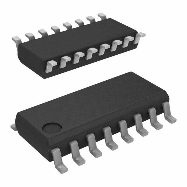
• Available in 16-pin SOIC package
• Supports 3.3V operation
• TTL compatible logic: VIL = 0.8V max., VIH = 2.0V min.,
VOL = 0.4V max., and VOH = 2.4V min.
• OE pin has internal pull-up
Functional Description
The W173 has been defined to meet the timing signal requirements for Hewlett Packard CPB tape drive system.
S
Block Diagram
REFIN
Pin Configuration
XTAL
OSC
13.2 MHz
PLL 1
6.6 MHz
VDD
1
16
VDD
X1
2
15
6.6MHZ
X2
3
14
GND
GND
4
13
13.2MHZ
OE
5
12
VDD
VDD
6
11
50MHZ
7
GND
10MHZ
GND
8
10
9
VDD
50 MHz
PLL 2
10 MHz
OE
..........Document #: 38-07313 Rev. *B Page Page 1 of 5 of 5
400 West Cesar Chavez, Austin, TX 78701
1+(512) 416-8500
1+(512) 416-9669
www.silabs.com
�W173
Pin Definitions
Pin Name
[1]
Pin No.
Pin Type
Pin Description
OE
5
I
Output Enable: When LOW, this input signal puts all outputs into a high-impedance
state.
13.2MHZ
13
O
Clock Output: Provides a TTL-level timing signal proportional in frequency to the
input signal. For a 26.5625 MHz reference, the frequency will be 13.2 MHz.
6.6MHZ
15
O
Clock Output: Provides a TTL-level timing signal proportional in frequency to the
input signal. For a 26.5625 MHz reference, the frequency will be 6.6 MHz.
10MHZ
10
O
Clock Output: Provides a TTL-level timing signal proportional in frequency to the
input signal. For a 26.5625 MHz reference, the frequency will be 10.0 MHz.
50MHZ
7
O
Clock Output: Provides a TTL-level timing signal proportional in frequency to the
input signal. For a 26.5625 MHz reference, the frequency will be 50.0 MHz.
X1
2
I
External Crystal Connection: This pin has dual functions. It can be used as an
external 26.5625 MHz crystal connection or as an external reference frequency
input.
X2
3
O
External Crystal Connection: An input connection for an external 26.5625 MHz
crystal. If using an external reference, this pin must be left unconnected.
VDD
1, 6, 9, 12, 16
P
Power Supply Connections: Connect both VDD pins to the same voltage, either
3.3V or 5.0V. Each VDD pin should have a decoupling capacitor (such as 0.1 µF)
placed as close to the pin as possible.
GND
4, 8, 11, 14
G
Ground Connections: Connect all ground pins to the common system ground
plane.
Note:
1. All inputs, except X1 or X2, have an internal pull-up resistor. Unconnected inputs will assume a logic HIGH condition.
......... Document #: 38-07313 Rev. *B Page Page 2 of 5 of 5
�W173
Power Supply Connections
The recommended single voltage power supply configuration
for the W173 is shown schematically in Figure 1. These recommendations should be followed to both ensure adequate
device performance and to control EMI. The major considerations can be summarized as follows:
1. Decoupling Capacitor—A 0.1-µF decoupling capacitor
should be used for each VDD pin to minimize crosstalk between output frequencies. The trace to the VDD pin and to
the ground via should be as short as possible.
0.1 µF
All ground connections should be made to the main system
ground plane. These connections should be as short as
possible. No cuts should be made in the ground plane around
the clock device since this can increase system EMI and
reduce clock performance.
1. The clock line width should be set to provide a 60 trace
impedance. This width will vary depending on the PCB material; the PCB supplier can suggest what width to use for
a 60 clock line. In general, an 8-mil trace will provide a
60impedance on a multi-level board.
2. The series termination resistor (sometimes called “damping
resistor”) must be placed in series with the clock line as
close to the clock output as possible (within one inch).
3. Assume an output resistance from the W173 of 40,
choose series resistors appropriate to the number of driven
traces.
FB
22 µF
C1
VDD
1
16
VDD
X1
2
15
6.6MHz
14
GND
13
13.2MHz
12
VDD
X2
3
GND
4
OE
5
VDD
6
11
GND
50MHz
GND
7
10
10MHz
8
9
VDD
W173
0.1 µF
Ground Connections
Clock Output Lines
2. Ferrite Bead (FB)—A common supply connection should
be used for all W173 VDD pins. A ferrite bead should be
used on this common supply as shown to remove high
frequency system noise.
3. 22-µF Supply Filter Capacitor—The 22-µF capacitor filters
low frequency supply noise that may produce clock output
jitter. Depending on the particular application, this capacitor
may not be required; its use should be considered optional.
Mounting pads should be implemented in PCB layout. Use
of this capacitor in production should be determined upon
prototype evaluation.
System VDD
4. PCB power supply traces should be at least 20 mils wide to
assure adequate trade impedance recommend Power
Supply Schematic–Single Voltage Supply Operation.
Figure 1. Test Circuit
......... Document #: 38-07313 Rev. *B Page Page 3 of 5 of 5
0.1 µF
0.1 µF
0.1 µF
�W173
Absolute Maximum Ratings[2]
Stresses greater than those listed in this table may cause
permanent damage to the device. These represent a stress
rating only. Operation of the device at these or any other condi-
tions above those specified in the operating sections of this
specification is not implied. Maximum conditions for extended
periods may affect reliability.
Table 1:
Parameter
Description
Rating
Unit
VDD, VIN
Voltage on Any Pin with Respect to GND
–0.5 to +7.0
V
TSTG
Storage Temperature
–65 to +150
°C
TB
Ambient Temperature under Bias
–55 to +125
°C
TA
Operating Temperature
0 to +70
°C
DC Electrical Characteristics: TA = 0°C to +70°C, VDD = 3.3V±5%
Parameter
Description
Test Condition
IDD
Supply Current
VIL
Input Low Voltage
VCC = 5.0V
VIH
Input High Voltage
VCC = 5.0V
Min.
Typ.
Note: CLK output = 50.0 MHz
output loaded
VOL
Output Low Voltage
IOL = 1 mA
VOH
Output High Voltage
IOH = –1 mA
Max.
Unit
40
mA
0.8
2.0
V
V
50
3.1
mV
V
IIL
Input Low Current
10
µA
IIH
Input High Current
10
µA
RP
Input Pull-up Resistor
VIN = 0V
CI
Input Capacitance
Except X1 and X2
LI
Input Inductance
Except X1 and X2
CL
XTAL Load Capacitance
Total load to crystal
k
500
6
pF
7
nH
12
pF
AC Electrical Characteristics: TA = 0°C to +70°C, VCC = 3.3V±5%[3]
Parameter
Description
Test Condition
Min.
Typ.
Max.
Unit
±175
±250
ps
Clock Outputs
tJC
Output Clock Jitter, Cycle-to-Cycle Excluding 13.2-MHz output
ZO
Output Buffer Impedance
40
W
dT
Output Duty Cycle
45
50
55
%
tR
Rise Time
Between 0.4V and 2.4V
0.8
1.5
4.0
V/ns
tF
Fall Time
Between 2.4V and 0.4V
0.8
1.5
4.0
V/ns
tPU
Stabilization Time from Power-Up To within 0.1% of final frequency
1.5
3.0
ms
fA
Long Term Output Frequency
Stability
0.01
%
Over VCC and TA range
Note:
2. Multiple Supplies: The Voltage on any input or I/O pin cannot exceed the power pin during power-up. Power supply sequencing is NOT required.
3. All AC tests are performed using the circuit shown in Figure 1 to simulate typical system load conditions. Measurements are taken at the load. Threshold voltage
for timing measurements is 1.5V.
......... Document #: 38-07313 Rev. *B Page Page 4 of 5 of 5
�W173
Ordering Information
Ordering Code
Package Type
W173G
16-pin SOIC (150 mil)
W173GT
16-pin SOIC (150 mil) - Tape and Reel
Lead Free
CYW173SXC
16-pin SOIC (150 mil)
CYW173SXCT
16-pin SOIC (150 mil) - Tape and Reel
Package Drawing and Dimensions
16-Lead (150-Mil) SOIC S16.15
16 Lead (150 Mil) SOIC
PIN 1 ID
8
1
DIMENSIONS IN INCHES[MM] MIN.
MAX.
REFERENCE JEDEC MS-012
PACKAGE WEIGHT 0.15gms
0.150[3.810]
0.157[3.987]
0.230[5.842]
0.244[6.197]
PART #
S16.15 STANDARD PKG.
SZ16.15 LEAD FREE PKG.
9
16
0.386[9.804]
0.393[9.982]
0.010[0.254]
0.016[0.406]
SEATING PLANE
X 45°
0.061[1.549]
0.068[1.727]
0.004[0.102]
0.050[1.270]
BSC
0°~8°
0.0138[0.350]
0.0192[0.487]
0.004[0.102]
0.0098[0.249]
0.016[0.406]
0.035[0.889]
0.0075[0.190]
0.0098[0.249]
The information in this document is believed to be accurate in all respects at the time of publication but is subject to change without notice. Silicon Laboratories assumes no responsibility for errors and omissions, and disclaims responsibility for any consequences resulting from the
use of information included herein. Additionally, Silicon Laboratories assumes no responsibility for the functioning of undescribed features or
parameters. Silicon Laboratories reserves the right to make changes without further notice. Silicon Laboratories makes no warranty, representation or guarantee regarding the suitability of its products for any particular purpose, nor does Silicon Laboratories assume any liability
arising out of the application or use of any product or circuit, and specifically disclaims any and all liability, including without limitation consequential or incidental damages. Silicon Laboratories products are not designed, intended, or authorized for use in applications intended to
support or sustain life, or for any other application in which the failure of the Silicon Laboratories product could create a situation where personal injury or death may occur. Should Buyer purchase or use Silicon Laboratories products for any such unintended or unauthorized application, Buyer shall indemnify and hold Silicon Laboratories harmless against all claims and damages.
......... Document #: 38-07313 Rev. *B Page Page 5 of 5 of 5
�
很抱歉,暂时无法提供与“CYW173SXC”相匹配的价格&库存,您可以联系我们找货
免费人工找货