®
SP6644/6645
Single/Dual Alkaline Cell, High Efficiency
Boost DC-DC Regulator
■ 90mA Output Current at 1.3V Input
■ 190mA Output Current at 2.6V Input
■ +2V to +5.5V Output Range
■ 0.88V Guaranteed Start-Up
■ 92% High Efficiency
■ 1.6µA Quiescent Supply Current at VBATT
■ Reverse Battery Protection
■ Internal Synchronous Rectifier
■ 5nA Logic Controlled Shutdown Current
From VBATT
■ Low-Battery Detection Active LOW Output
V B AT 1
B AT T L 0 2
RLIM 3
SHDN 4
SP6644
SP6645
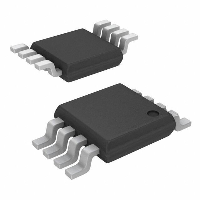
8 Pin MSOP
8 V OUT
7 LX
6 GND
4 FB
Now Available in Lead Free Packaging
■ Small 8 Pin MSOP Package
■ No External FETs
■ Flexibility to Optimize Inductor Type
with Programmable Peak Current
Control
DESCRIPTION
The SP6644/6645 devices are high-efficiency, low-power step-up DC-DC converters ideal
for single or dual alkaline cell applications such as pagers, remote controls, pointing devices,
medical monitors, and other low-power portable end products. Designers can control the
SP6644 device with an active LOW shutdown input. The SP6644 device features an active
low output for batteries below +1.0V. The SP6645 device features an active low output for
batteries below +2.0V. Both devices contain a 0.8Ω synchronous rectifier, a 0.5Ω
N-channel MOSFET power switch, an internal voltage reference, circuitry for pulsefrequency-modulation, and an under voltage comparator. The output voltage for the
SP6644/6645 devices is preset to +3.3V + 4% or can be adjusted from +2V to +5.5V by
manipulating two external resistors
TYPICAL APPLICATION CIRCUIT
22µH
0.7A
0.88V to
3.3V Input
VBATT
47µF
LX
VOUT
RLIM
+3.3VOUT
SP6644
SP6645
47µF
BATTLO
SHDN
FB
GND
Date: 11/30/04
SP6644/6645 High Efficiency Boost Regulator
1
© Copyright 2004 Sipex Corporation
�ABSOLUTE MAXIMUM RATINGS
These are stress ratings only and functional operation of the
device at these ratings or any other above those indicated in
the operation sections of the specifications below is not
implied. Exposure to absolute maximum rating conditions for
extended periods of time may affect reliability.
VBATT to GND.............................................-0.3 to 6.0V
VOUT to GND..............................................-0.3 to 6.0V
LX, SHDN, FB, BATTLO, to GND.............-0.3 to 6.0V
Reverse battery Current, TAMB=+25˚C.............220mA
(NOTE 1)
VBATT forward current............................................0.5A
VOUT, LX current......................................................1A
Storage Temperature Range............-65˚C to +165˚C
Lead Temperature (soldering 10s)..................+300˚C
Operating Temperature.......................-40˚C to +85˚C
Power Dissipation Per Package
8-pin µSOIC (derate 4.85mW/OC above +70OC)..........390mW
ELECTRICAL CHARACTERISTICS
o
VBATT = VSHDN = 1.3V, ILOAD = 0mA, FB = GND, TAMB = -40 C to +85 C, and typical values are at TAMB = +25oC unless otherwise noted.
PARAMETER
MIN.
o
TYP.
Maximum Operating Input Voltage,
VBATT(MAX)
Start-Up Input Voltage, VBATT
0.82
Start-Up Input Voltage, VBATT
Temperature Coefficient
-1
SHDN Input Voltage
VIL
VIH
MAX.
UNITS
♦
3.3
V
♦
1.1
V
♦
CONDITIONS
RL = 3kΩ,
mVºC
15
%
% of VBATT
% of VBATT
80
SHDN Input Current
1
10 0
nA
♦
FB Input Current
1
10 0
nA
♦
VFB =1.3V,
FB Set Voltage, VFB
1.215
1.262
1.309
V
♦
external feedback
BATTLO Falling Trip Voltage
0.94
1.88
1.00
2.00
1.06
2.12
V
♦
SP6644, VOUT = 3.3V
SP6645, VOUT = 3.3V
Output Voltage, VOUT
3.16
3.30
3.44
V
♦
VFB
很抱歉,暂时无法提供与“SP6644EU-L”相匹配的价格&库存,您可以联系我们找货
免费人工找货