Not Recommended for New Designs
(Suggested Alternate: XRP7714 with XR7620x frontend)
XR77129
40V Quad Output Digital PWM/PFM
Universal PMIC
FEATURES
General Description
The XR77129 is a quad channel digital Pulse Width Modulated (PWM)
step down (buck) controller. A wide 6V to 40V input voltage range allows
for single supply operation from standard power rails.
With integrated FET gate drivers, two LDOs for standby power and a
105kHz to 1.23MHz independent channel to channel programmable
constant operating frequency, the XR77129 reduces overall component
count, solution footprint and optimizes conversion efficiencies. A
selectable digital Pulse Frequency Mode (PFM) capable of better than
80% efficiency at light current load and low operating current allow for
portable and Energy Star compliant applications. Each XR77129
channel’s output voltage is individually programmable down to 0.6V with a
resolution of 2.5mV, and is configurable for precise soft start and soft stop
sequencing, including delay and ramp control.
2
The XR77129 operations are fully controlled via a SMBus-compliant I C
interface allowing for advanced local and/or remote reconfiguration, full
performance monitoring and reporting as well as fault handling.
Built-in independent output Over-Voltage, Over-Temperature, OverCurrent and Under-Voltage Lockout protections insure safe operation
under abnormal operating conditions.
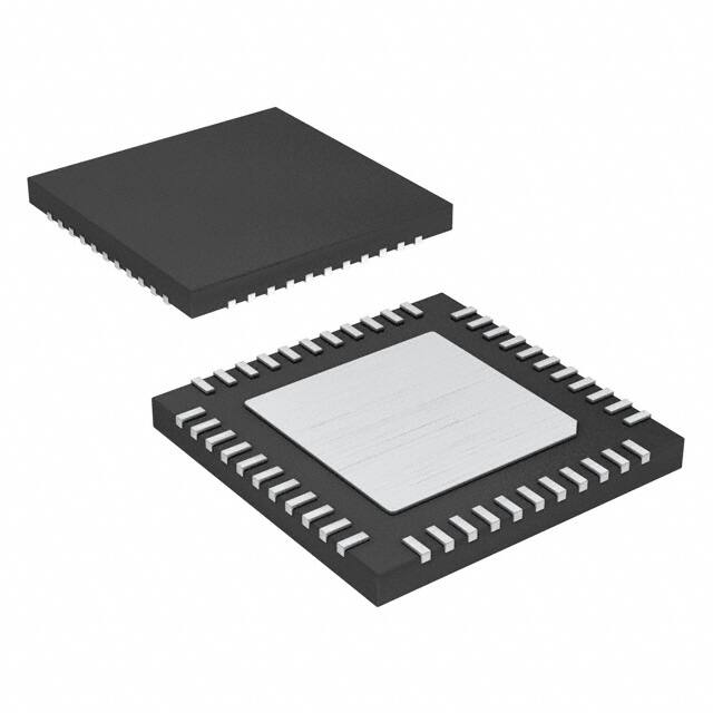
The XR77129 is offered in a RoHS compliant, “green”/halogen free 44-pin
TQFN package.
Quad Channel Step-down Controller
Digital PWM 105kHz-1.23MHz Operation
Individual Channel Frequency Selection
Patented digital PFM with Ultrasonic mode
Patented Over Sampling Feedback
Programmable 5 coefficient PID control
Integrated MOSFET Drivers
6V to 40V Input Voltage
0.6V to 5.5V Output Voltage (higher with
external feedback resistors)
SMBus Compliant I2C Interface
Full Power Monitoring and Reporting
3 x 15V Capable PSIO + 2 x GPIOs
Full Start/Stop Sequencing Support
Built-in Thermal, Over-Current, UVLO and
Output Over-Voltage Protections
On Board 5V and LDOOUT Standby LDOs
On Board Non-Volatile Memory
Supported by PowerArchitect™ (PA5)
APPLICATIONS
Industrial Control Systems
Automatic Test Equipment
Video Surveillance Systems
Automotive Infotainment
Ordering Information – back page
Typical Application
1 / 29
exar.com/XR77129
Rev 1C
�Not Recommended for New Designs
(Suggested Alternate: XRP7714 with XR7620x frontend)
XR77129
Absolute Maximum Ratings
Operating Conditions
Stresses beyond the limits listed below may cause
permanent damage to the device. Exposure to any
Absolute Maximum Rating condition for extended periods
may affect device reliability and lifetime.
Input Voltage Range VCC................................................6V to 40V
VCCD, LDO5, LDOOUT, GLx, VOUTx........................-0.3V to 7.0V
JEDEC Thermal Resistance JA.........................................32°C/W
VOUT1, 2, 3, 4.........................................................................5.5V
Junction Temperature Range................................-40°C to +125°C
ENABLE, V5EXT.........................................................-0.3V to 7.0V
GPIO0/1, SCL, SDA.................................................................6.0V
PSIO Inputs, BFB......................................................................18V
DVDD, AVDD...........................................................................2.0V
VCC..........................................................................................43V
LX#.................................................................................-1V to 43V
BSTx, GHx........................................................................VLx + 6V
Storage Temperature.............................................-65°C to +150°C
Power Dissipation................................................Internally Limited
Lead Temperature (Soldering, 10 sec)..................................300°C
ESD Rating (HBM - Human Body Model).................................2kV
Electrical Characteristics
Unless otherwise noted: TJ= 25°C, VCC=6V to 40V, V5EXT open. Limits applying over the full operating temperature range
are denoted by a “•”
Symbol
Parameter
Conditions
Min
Typ
Max
Units
SHUTDOWN
EN = 0V, VCC = 24V
20
30
µA
STANDBY
I/Os programmed as inputs, VCC = 12V,
EN = 5V
550
650
µA
2ch PFM
2 channels on set at 5V, VOUT forced to
5.1V, no load, non-switching, ultra-sonic
3.1
mA
4.0
mA
18
mA
Quiescent Current
ISUPPLY
VCC Supply Current
off, VCC = 12V, no I2C activity
4ch PFM
4 channels on set at 5V, VOUT forced to
5.1V, no load, non-switching, ultra-sonic
off, VCC = 12V, no I2C activity
4ch PWM
All channels enabled, fsw = 600kHz, gate
drivers unloaded, no I2C activity
2 / 29
exar.com/XR77129
Rev 1C
�Not Recommended for New Designs
(Suggested Alternate: XRP7714 with XR7620x frontend)
Symbol
Parameter
Conditions
VENABLE
ENABLE Turn On Threshold
VCC = 12V, Enable Rising
ILEAK
ENABLE Pin Leakage Current
EN = 5V
Min
XR77129
Typ
0.65
3.6
EN = 0V
Max
Units
0.95
V
10
µA
-10
µA
Input Voltage Range and Undervoltage Lockout
VCC
VCC Range
6
40
V
-5
5
mV
-12.5
12.5
mV
-10
10
mV
-25
25
mV
-20
20
mV
-50
50
mV
0.6
5.5
V
Voltage Feedback Accuracy and Output Voltage Set Point Resolution
VA_VO
VOUT Regulation Accuracy
Low Output Range
0.6 ≤ VOUT ≤ 1.6V, PWM operation
Mid Output Range
0.6 ≤ VOUT ≤ 3.2V, PWM operation
High Output Range
0.6 ≤ VOUT ≤ 5.5V, PWM operation
VR_VO
VOUT Regulation Range
Without external divider network
VNATIVE
VOUT Native Set Point Resolution
Low Range
12.5
mV
Mid Range
25
mV
High Range
50
mV
Low Range
2.5
mV
Mid Range
5
mV
High Range
10
mV
Low Range
120
kΩ
Mid Range
80
kΩ
High Range
65
kΩ
Low Range
10
MΩ
Mid Range
1
MΩ
High Range
0.67
MΩ
VFINE
RIN
RIN
VSET_PG
VSET_PG
VOUT Fine Set Point Resolution1
VOUT Input Resistance
VOUT Input Resistance in PFM
Power Good and OVP Set Point
Range (from set point)
Power Good and OVP Set Point
Accuracy
VSET_BF
BFB Set Point Range
VRES_BF
BFB Set Point Resolution
VA_BF
BFB Accuracy
Low Range
-155
157.5
mV
Mid Range
-310
315
mV
High Range
-620
630
mV
Low Range
-5
5
mV
Mid Range
-10
10
mV
High Range
-20
20
mV
9
16
V
1
-0.5
3 / 29
V
0.5
V
exar.com/XR77129
Rev 1C
�Not Recommended for New Designs
(Suggested Alternate: XRP7714 with XR7620x frontend)
Symbol
Parameter
Conditions
XR77129
Min
Typ
Max
Units
-2.5
±1.25
2.5
mV
6.25
mV
5
mV
12.5
mV
Current and AUX ADC (Monitoring ADCs)
VA_CS
Current Sense Accuracy
Low Range (≤120mV), -60mV applied
High Range (≤280mV), 150mV applied
-6.25
-5
±2.5
-12.5
INLCS
Current Sense ADC INL
±0.4
LSB
DNLCS
Current Sense DNL
±0.4
LSB
VSET_CS
Current Limit Set Point Resolution
and Current Sense ADC Resolution
Low Range (≤120mV)
1.25
mV
High Range (≤280mV)
2.5
mV
Current Sense ADC Range
Low Range (≤120mV)
-120
20
mV
High Range (≤280mV)
-280
40
mV
VCS
VADC_VO
VOUT ADC Resolution
Low Range
15
mV
Mid Range
30
mV
High Range
60
mV
LSBADC
VOUT ADC Accuracy
-1
1
LSB
VADC
VCC ADC Range
5.0
51.2
V
VR_ADC
VCC ADC Resolution
VA_ADC
VCC ADC Accuracy
TR_ADC
Die Temp ADC Resolution
TADC
Die Temp ADC Range
400
VCC ≤ 20V
-1
mV
1
5
Output value is in Kelvin
-44
LSB
°C
156
°C
Linear Regulators
VO_LDO5
LDO5 Output Voltage
5.5V ≤ VCC ≤ 25V
0mA < ILDO5OUT < 130mA, LDOOUT off
4.85
5.0
5.15
V
ICL_LDO5
LDO5 Current Limit
LDO5 Fault Set
135
155
180
mA
LDO5 UVLO
VCC Rising
4.6
LDO5 PGOOD Hysteresis
VCC Falling
V
375
LDO5 Bypass Switch Resistance
1.1
2.5
Bypass Switch Activation Threshold
V5EXT Rising, % of threshold setting
Bypass Switch Activation Hysteresis
V5EXT Falling
LDOOUT Output Voltage
4.6V ≤ LDO5 ≤ 5.5V
0mA < ILDOOUT < 50mA
LDOOUT set to 3.3V
3.15
LDOOUT Current Limit
LDOOUT Fault Set, LDOOUT set to 3.3V
50
Maximum total LDO5 loading during
ENABLE start-up
ENABLE transition from logic low to high.
Once LDO5 in regulation, above limits
apply.
mV
1.5
Ω
2.5
%
150
4 / 29
3.3
mV
3.45
V
85
mA
75
mA
exar.com/XR77129
Rev 1C
�Not Recommended for New Designs
(Suggested Alternate: XRP7714 with XR7620x frontend)
Symbol
Parameter
Conditions
Min
XR77129
Typ
Max
Units
105
1230
kHz
-5
5
%
PWM Generators and Oscillator
fSW
Switching Frequency Range
Steps defined in table
Switching Frequency Accuracy
fCLKIN
CLOCK IN Synchronization Frequency
When synchronizing to an external clock
(Range 1)
20
25.7
31
MHz
When synchronizing to an external clock
(Range 2)
10
12.8
15.5
MHz
0.8
V
I2C and GPIOs2
VIL
Input Pin Low Level
VIH
Input Pin High Level
1.35
V
Input Pin Leakage Current
VOL
Output Pin Low Level
ISINK = 1mA
VOH
Output Pin High Level
ISOURCE = 1mA
1
µA
0.4
V
2.4
ISOURCE = 0mA
V
3.3
3.6
V
10
µA
1
mA
I/O Frequency
30
MHz
VIL
Input Pin Low Level
0.8
V
VIH
Input Pin High Level
PSIO0 and PSIO1
VIH
Input Pin High Level
PSIO2
Output Pin High-Z Leakage Current
(GPIO pins only)
Maximum Sink Current
Open Drain Mode
PSIOs3
2
V
1.35
V
Input Pin Leakage Current
1
µA
VOL
Output Pin Low Level
ISINK = 3mA
0.4
V
VOH
Output Pin High Level
Open Drain. External pull-up resistor to
user supply.
15
V
Output Pin High-Z Leakage Current
(PSIO pins only)
10
µA
I/O Frequency
5
MHz
0.3VIO
V
SMBus (I2C) Interface
VIL
Input Pin Low Level
VIO = 3.3V ±10%
VIH
Input Pin High Level
VIO = 3.3V ±10%
0.7VIO
V
VHYS
Hysteresis of Schmitt Trigger Inputs
VIO = 3.3V ±10%
0.05
VIO
V
VOL
Output Pin Low Level (open drain or
collector)
ISINK = 3mA
ILEAK
Input Leakage Current
Input is between 0.1VIO and 0.9VIO
5 / 29
-10
0.4
V
10
µA
exar.com/XR77129
Rev 1C
�Not Recommended for New Designs
(Suggested Alternate: XRP7714 with XR7620x frontend)
Symbol
Parameter
Output Fall Time from VIHmin to VILmax
Conditions
Min
With a bus capacitance (Cb) from 10pF to
400pF
20 +
0.1Cb
XR77129
Typ
Internal Pin Capacitance
Max
Units
250
ns
1
pF
Gate Drivers
GH, GL Rise Time
At 10-90% of full scale, 1nF Cload
17
ns
GH, GL Fall Time
At 10-90% of full scale, 1nF Cload
11
ns
GH, GL Pull-Up On-State Output
Resistance
4.35
5
Ω
GH, GL Pull-Down On-State Output
Resistance
1.96
2.5
Ω
GH, GL Pull-Down Off-Mode Resistance
VCC = VCCD = 0V
48
kΩ
Bootstrap Diode Forward Resistance
at 10mA
8.5
Ω
Minimum On-Time
1nF of gate capacitance
50
ns
Minimum Off-Time
1nF of gate capacitance
125
ns
Minimum Programmable Dead Time
Does not include dead time variation from
driver output stage, TSW = switching
period
20
ns
TSW
103MHz internal clock frequency
607
Maximum Programmable Dead Time
Programmable Dead Time Adjustment Step
ps
Note 1: Fine Set Point Resolution not available in PFM
Note 2: 3.3V CMOS logic compatible, 5V tolerant
Note 3: 3.3V/5.0V CMOS logic compatible, maximum rating of 15.0V
6 / 29
exar.com/XR77129
Rev 1C
�Not Recommended for New Designs
(Suggested Alternate: XRP7714 with XR7620x frontend)
XR77129
Pin Configuration
Pin Assignments
Pin No.
Pin Name
Description
1
LDOOUT
Output of the standby LDO. This is a micro power LDO that needs to be configured or
commanded to turn on.
2
AGND
Analog ground pin. This is the small signal ground connection.
3
CPLL
Connect to a 2.2nF capacitor to GND.
4
AVDD
Output of the internal 1.8V LDO. A decoupling capacitor should be placed between AVDD and
AGND close to the chip.
VOUT1, VOUT2, VOUT3, VOUT4
Connect to the output of the corresponding power stage.The output is sampled at least once
every switching cycle.
GPIO0, GPIO1
These pins can be configured as inputs or outputs to implement custom flags, power good
signals, enable/disable controls and synchronization to an external clock.
SDA, SCL
SMBus/I2C serial interface communication pins.
5, 6, 7, 8
9,10
11, 12
7 / 29
exar.com/XR77129
Rev 1C
�Not Recommended for New Designs
(Suggested Alternate: XRP7714 with XR7620x frontend)
Pin No.
13, 14,
15
Pin Name
XR77129
Description
PSIO0, PSIO1, PSIO2
Open drain, these pins can be used to control external power MOSFETs to switch loads on
and off, shedding the load for fine grained power management. They can also be configures as
standard logic outputs or inputs just as any of the GPIOs can be configured, but as open
drains require an external pull-up when configured as outputs.
16
DVDD
1.8V supply input for digital circuitry. Connect pin to AVDD. Place a decoupling capacitor close
to the controller IC.
17
DGND
Digital ground pin. This is the logic ground connection, and should be connected to the ground
plane close to the PAD.
18, 24,
29, 35
BST4, BST3, BST2, BST1
High side driver supply pin(s). Connect BST to the external capacitor as shown in the Typical
Application Circuit. The high side driver is connected between the BST pin and LX pin and
delivers the BST pin voltage to the high side FET gate each cycle.
19, 25,
30, 36
GH4, GH3, GH2, GH1
Output pin of the high side gate driver. Connect directly to the gate of an external N-channel
MOSFET.
20, 26,
31, 37
LX4, LX3, LX2, LX1
Lower supply rail for the GH high-side gate driver. Connect this pin to the switching node at the
junction between the two external power MOSFETs and the inductor. These pins are also
used to measure voltage drop across bottom MOSFETs in order to provide output current
information to the control engine.
21, 27,
32, 38
GL4, GL3, GL2, GL1
Output pin of the low side gate driver. Connect directly to the gate of an external N-channel
MOSFET.
22, 28,
33, 39
GL_RTN4, GL_RTN3, GL_RTN2,
GL_RTN1
Ground connection for the low side gate driver. This should be routed as a signal trace with
GL. Connect to the source of the low side MOSFET.
23, 34
VCCD3-4, VCCD1-2
Gate Drive supply. Two independent gate drive supply pins where pin 34 supplies drivers 1 and
2 and pin 23 supplies drivers 3 and 4. One of the two pins must be connected to the LDO5 pin
to enable two power rails initially. It is recommended that the other VCCD pin be connected to
the output of a 5V switching rail (for improved efficiency or for driving larger external FETs), if
available, otherwise this pin may also be connected to the LDO5 pin. A bypass capacitor
(>1uF) to the system ground is recommended for each VCCD pin with the pin(s) connected to
LDO5 with shortest possible length of etch.
40
ENABLE
If ENABLE is pulled high or allowed to float high, the chip is powered up (logic is reset,
registers configuration loaded, etc.). The pin must be held low for the XR77129 to be placed
into shutdown.
41
VCC
Input voltage. Place a decoupling capacitor close to the controller IC. This input is used in
UVLO fault generation.
42
BFB
Input from the 15V output created by the external boost supply. When this pin goes below a
pre-defined threshold, a pulse is created on the low side drive to charge this output back to the
original level. If not used, this pin should be connected to GND.
43
V5EXT
External 5V that can be provided. If one of the output channels is configured for 5V, then this
voltage can be fed back to this pin for reduced operating current of the chip and improved
efficiency.
44
LDO5
Output of a 5V LDO. This LDO is used to power the internal Analog Blocks.
45
PAD
This is the die attach paddle, which is exposed on the bottom of the part. Connect externally to
the ground plane.
8 / 29
exar.com/XR77129
Rev 1C
�Not Recommended for New Designs
(Suggested Alternate: XRP7714 with XR7620x frontend)
XR77129
Functional Block Diagram
XR77129 Block Diagram
LDO Block Diagram
9 / 29
exar.com/XR77129
Rev 1C
�Not Recommended for New Designs
(Suggested Alternate: XRP7714 with XR7620x frontend)
XR77129
Typical Performance Characteristics
Unless otherwise noted: VCC = 12V, TA = 25°C
Figure 1: PFM to PWM Transition
Figure 2: PWM to PFM Transition
Figure 3: 0-6A Transient 300kHz PWM only
Figure 4: 0-6A Transient 300kHz with OVS +/-5%
Figure 5: PFM Zero Current Accuracy
Figure 6: LDO5 Brown Out Recovery, No Load
10 / 29
exar.com/XR77129
Rev 1C
�Not Recommended for New Designs
(Suggested Alternate: XRP7714 with XR7620x frontend)
XR77129
Figure 7: Sequential, Conditional Start-Up
Figure 8: Sequential, Conditional Shut-Down
Figure 9: Simultaneous Start-Up
Figure 10: Simultaneous Shut-Down
Figure 11: Ramp-Up Rate Dynamic Sweep
Figure 12: Ramp-Down Rate Dynamic Sweep
11 / 29
exar.com/XR77129
Rev 1C
�Not Recommended for New Designs
(Suggested Alternate: XRP7714 with XR7620x frontend)
XR77129
Figure 13: Start-Up Delay Dynamic Sweep
Figure 14: Shut-Down Delay Dynamic Sweep
Figure 15: Shut-Down Current Versus VCC
Figure 16: Enable Threshold Over Temperature at VCC=12V
12 / 29
exar.com/XR77129
Rev 1C
�Not Recommended for New Designs
(Suggested Alternate: XRP7714 with XR7620x frontend)
Functional Description
Overview
The XR77129 is a quad-output digital pulse width
modulation (PWM) controller with integrated gate drivers for
use with synchronous buck switching regulators. Each
output voltage can be programmed from 0.6V to 5.5V
without the need for an external voltage divider. The wide
range of programmable PWM switching frequency (from
105kHz to 1.2MHz) enables the user to optimize for
efficiency or component sizes. Since the digital regulation
loop requires no external passive components, loop
performance is not compromised due to external
component variation or operating condition.
The XR77129 provides a number of critical safety features
such as Over-Current Protection (OCP), Over-Voltage
Protection (OVP), Over-Temperature Protection (OTP), plus
input Under-Voltage Lockout (UVLO). In addition, it has a
number of key health monitoring features such as warning
level flags for the safety functions, Power Good (PGOOD),
etc., plus full monitoring of system voltages and currents.
The above are all programmable and/or readable from the
SMBus and many are steerable to the IOs for hardware
monitoring.
XR77129
configuration, control and monitoring information for the
chip. The second type is rewritable Non-Volatile Flash
Memory that is used for permanent storage of the
configuration data along with various chip internal
functions. During power up, the run time registers are
loaded from the flash memory allowing for standalone
operation.
The XR77129 brings an extremely high level of functionality
and performance to a programmable power system. Ever
decreasing product budgets require the designer to quickly
make good cost / performance trade-offs to be truly
successful. By incorporating 4 switching channels, two user
LDOs, a charge pump boost controller, along with internal
gate drivers, all in a single package, the XR77129 allows for
extremely cost effective power system designs. Another key
cost factor that is often overlooked is the unanticipated
Engineering Change Order (ECO). The programmable
versatility of the XR77129, along with the lack of hard wired
configuration components, allows for minor and major
changes to be made in circuit by simple reprogramming.
For hardware communication, the XR77129 has two logic
level General Purpose Input-Output (GPIO) pins and three
15V, open drain, Power System Input-Output (PSIO) pins.
Two pins are dedicated to the SMBus data (SDA) and clock
(SCL). Additional pins include Chip Enable (Enable), Aux
Boost Feedback (BFB) and External PLL Capacitor (CPLL).
In addition to providing four switching outputs, the XR77129
also provides control for an Aux boost supply, and two
stand-by linear regulators for a total of seven customer
usable supplies in a single device.
The 5V LDO is used for internal power and is also available
for customer use to power external circuitry. LDOOUT is
solely for customer use and is not used by the chip. There
is also a 1.8V linear regulator which is for internal use only
and should not be used externally.
A key feature of the XR77129 is its advanced power
management capabilities.
All four outputs are
independently programmable and provide the user full
control of the delay, ramp, and sequence during power up
and power down. The user may also control how the
outputs interact and power down in the event of a fault. This
includes active ramp down of the output voltages to remove
an output voltage as quickly as possible. Another useful
feature is that the outputs can be defined and controlled as
groups.
The XR77129 has two main types of programmable
memory. The first type is runtime registers that contain
13 / 29
exar.com/XR77129
Rev 1C
�Not Recommended for New Designs
(Suggested Alternate: XRP7714 with XR7620x frontend)
XR77129
Regulation Loops
Figure 17: Regulation Loops
Figure 17 shows a simplified functional block diagram of the
regulation loops for one output channel of the XR77129.
There are four separate parallel control loops: Pulse Width
Modulation (PWM), Pulse Frequency Modulation (PFM),
Ultrasonic, and Over Sampling (OVS). Each of these loops
is fed by the Analog Front End (AFE) as shown at the left of
the diagram. The AFE consist of an input voltage scaler, a
programmable Voltage Reference (Vref) DAC, Error
Amplifier, and a window comparator. Some of the functional
blocks are common and shared by each channel by means
of a multiplexer.
PWM Loop
The PWM loop operates in Voltage Control Mode (VCM)
with optional Vin feed forward based on the voltage at the
VCC pin. The reference voltage (Vref) for the error amp is
created by a 0.15V to 1.6V DAC that has a 12.5mV
resolution. In order to provide a 0.6V to 5.5V output voltage
range, an input scaler is used to reduce feedback voltages
for higher output voltages to bring them within the 0.15V to
1.6V control range. So for output voltages up to 1.6V (low
range), the scaler has a gain of 1. For output voltages from
1.6V to 3.2V (mid range) the scalar gain is 1/2, and for
voltages greater than 3.2V (high range) the gain is 1/4. This
results in the low range having a reference voltage
resolution of 12.5mV, the mid range having a resolution of
25mV, and the high range having a resolution of 50mV. The
error amp has a gain of 4 and compares the output voltage
of the scaler to Vref to create an error voltage on its output.
This is converted to a digital error term by the AFE ADC
and is stored in the error register. The error register has a
fine adjust function that can be used to improve the output
voltage set point resolution by a factor of 5 resulting in a low
range resolution of 2.5mV, a mid range resolution of 5mV
and a high range resolution of 10mV. The output of the error
register is then used by the Proportional Integral Derivative
(PID) controller to manage the loop dynamics.
The XR77129 PID is a 17-bit five-coefficient control engine
that calculates the required duty cycle under the various
operating conditions and feeds it to the digital Pulse Width
Modulator (PWM). Besides the normal coefficients, the PID
also uses the VCC voltage to provide a feed forward
function.
The XR77129 digital PWM includes a special delay timing
loop that provides a timing resolution that is 16 times the
master oscillator frequency (103MHz) for a timing resolution
of 607ps for both the driver pulse width and dead time
delays. The PWM produces the Gate High (GH) and Gate
Low (GL) signals to the driver. The maximum and minimum
on times and dead time delays are programmable by
configuration resisters.
To provide current information, the output inductor current
is measured by a differential amplifier that reads the voltage
drop across the RDSON of the synchronous FET during its
on time. There are two selectable ranges, a low range with
a gain of 8 for a -120mV to +20mV voltage range, and a
high range with a gain of 4 for -280mV to +40mV voltage
range. The optimum range to use will depend on the
maximum output current and the RDSON of the
synchronous FET. The measured voltage drop is then
converted to a digital value by the current ADC block. The
14 / 29
exar.com/XR77129
Rev 1C
�Not Recommended for New Designs
(Suggested Alternate: XRP7714 with XR7620x frontend)
resulting current value is stored in a readable register and
also used to determine when PWM to PFM transitions
should occur.
PFM Loop
The XR77129 has a PFM loop that can be enabled to
improve efficiency at light loads. By reducing switching
frequency and operating in the discontinuous conduction
mode (DCM), both switching and conduction losses are
minimized.
Figure 18 shows a functional diagram of the PFM logic.
# Cycles Reg
Default = 20
A
CHx Fsw
PFM Current
Threshold Reg
A
Clk
COUNTER
A