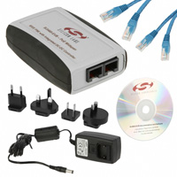
Si 3 4 6 0 - EVB
Si3460 E VALUATION B OARD U SER ’ S G U I D E
1. Introduction
This document is intended to be used in conjunction with the Si3460 data sheet for designers interested in:
An
Pl No
ea t
se Re
C com
on
si me
de n
r S de
i3 d f
46 or
2 N
fo ew
rN D
ew es
D ign
es s.
ig
ns
.
introduction to Power-over-Ethernet (PoE) and Power Sourcing Equipment (PSE) design
considerations
How the Si3460 PSE controller operates in the Si3460-EVB reference design
Configuring and operating the Si3460-EVB
2. Overview of the Si3460 and Evaluation Board
The Si3460 is a single-port –48 V power management controller for IEEE 802.3af compliant Power Sourcing
Equipment (PSE). The Si3460 operates directly from a 12 or 15 V isolated input supply and integrates a digital
PWM-based dc-dc converter for generating the –48 V PSE output supply. The negative polarity on the PSE supply
provides safety-extra-low-voltage (SELV) compatibility with telephony ports in the same system. The complete
Si3460 reference design (i.e., the Si3460-EVB) also provides full IEEE-compliant classification and detection as
well as a robust disconnect algorithm. Intelligent protection circuitry includes input under-voltage lockout (UVLO),
current limiting, and output short-circuit protection.
The Si3460 is designed to operate completely independently of host processor control. A reset input and an
optional LED status signal is provided to indicate the port status, including detect, power good and output fault
event information for use within the host system.
The Si3460 is pin programmable to support:
Endpoint
and midspan applications, with support for either 10/100BASE-T or 10/100/1000BASE-T
All four classification power levels specified by the IEEE 802.3 standard
Classification-based current limiting
Automatic or manual restart after various fault events are detected
3. Introduction to PoE
IEEE 802.3-2005 clause 33 (formerly IEEE 802.3af) is the standard for providing power to a remote Ethernet
device on the same cable that is carrying data. The power is either carried common mode on one of the data pairs
(for 10/100/1000BASE-T) or on the spare pairs for 10/100BASE-T only applications.
Figures 1 and 2 show the possible connections for the power. The connections shown in Figure 1 should be used
for power injection in an Ethernet midspan, and the connections shown in Figure 2 can be used for either midspan
or endpoint (switch) applications. Designed for use on the PSE side for providing power to a single Ethernet PD
port, the Si3460 can be configured to operate in either midspan or endpoint applications. Although at this time the
existing IEEE specification doesn't specifically allow or prohibit gigabit (10/100/1000BASE-T) midspans, in
midspan mode, the Si3460-EVB is designed to operate in 10/100BASE-T mode, as the power is carried on the
spare pairs. However, the Si3460 controller can also be designed into gigabit endpoints with the power connected
to either the data or spare pairs.
Rev. 1.2 3/13
Copyright © 2013 by Silicon Laboratories
Si3460-EVB
�Si3460-EVB
POWER SOURCING
EQUIPMENT (PSE)
POWERED DEVICE
(PD)
4
4
5
5
SPARE PAIR
TX
1
2
2
RX
PD I/F
and
DC-DC
Converter
Pl No
ea t
se Re
C com
on
si me
de n
r S de
i3 d f
46 or
2 N
fo ew
rN D
ew es
D ign
es s.
ig
ns
.
+
1
3
_
48 V
RX
SIGNAL PAIR
6
3
6
TX
SIGNAL PAIR
7
7
8
8
SPARE PAIR
Figure 1. Power Carried Over the Spare Pair (10/100BASE-T Applications Only)
Note: This is the connection scheme implemented on the Si3460-EVB reference design.
POWER SOURCING
EQUIPMENT (PSE)
POWERED DEVICE
(PD)
4
4
5
5
SPARE PAIR
±
48 V
±
TX
1
1
2
2
3
RX
SIGNAL PAIR
6
RX
3
6
DC-DC
Converter
and
PD I/F
TX
SIGNAL PAIR
7
7
8
8
SPARE PAIR
Figure 2. Power Carried Over the Signal (Data) Pair
2
Rev. 1.2
�Si3460-EVB
4. PSE Detection, Classification, Power-Up, and Power Removal
The basic sequence for applying power is shown in Figure 3. Following is a description of the functions that must
be performed in each phase.
57 V
Voltage
Pl No
ea t
se Re
C com
on
si me
de n
r S de
i3 d f
46 or
2 N
fo ew
rN D
ew es
D ign
es s.
ig
ns
.
44 V
20.5 V
15.5 V
10 V
Time
2.8 V
Detection
Classification
Apply Power
Turn off
Figure 3. Detection, Classification, Powerup, and Disconnect Sequence
4.1. Detection
During the detection phase, the PSE probes with limited current and voltage to determine if a 25 k signature is
present. A valid PD must present between 23.75 and 26.25 k in the range of 2.7 to 10.1 V, with an offset (due to
the bridge diodes) of up to 1.9 V, and a parallel capacitance of between 0.05 and 0.12 µF. An IEEE-compliant PSE
probes 2.8 and 10 V, with at least a 1 V step and current limit of 10 µF.
The strict limits on the detection phase ensure that non PoE enabled devices are not inadvertently powered. For
endpoint applications, detection must be completed within 500 ms of applying a valid signature. When configured
as a midspan there is a possibility that the PSE circuit will compete with an endpoint PSE, and, as required by the
IEEE specifications, the Si3460 is therefore required to wait at least 2 seconds after an unsuccessful detection
cycle to repeat the detection process.
Rev. 1.2
3
�Si3460-EVB
4.2. Classification
Classification is optional and is performed by applying between 15.5 and 20.5 V to the PD and measuring the
current. The maximum power level that can be drawn by the PD is determined according the following table.
Table 1. Classification Levels
Minimum PSE Power Level
Current Measured
Class 0
15.4 W
很抱歉,暂时无法提供与“SI3460-EVB”相匹配的价格&库存,您可以联系我们找货
免费人工找货