Si84xxCOM-EVB
S i 8 4 XX C M O S D IG ITA L I S O L A T O R - B ASED S ER IA L
I N T E R F A C E U S E R ’ S G U ID E
1. Introduction
SI84xx devices are CMOS-based galvanic isolators (1 kV/2.5 kV/5 kV) designed for industrial, commercial, and
medical isolation applications. They are available in various channel counts (1/2/3/4/5/6), speeds (1 and
150 Mbps), and options in two package options (narrow and wide body SOIC). They are also available in
unidirectional or bidirectional (I2C) channels option.
2. Kit Contents
The Si84xxCOM Evaluation Board contains the following items:
Si84xxCOM evaluation board show casing:
Si8442AB
4-channel unidirectional 1 Mbps digital isolator, narrow body, 2.5 kV
2-channel unidirectional 150 Mbps digital isolator, narrow body, 2.5 kV
Si8421AD 2-channel unidirectional 1 Mbps digital isolator, wide body, 5 kV*
*Note: The creepage and clearance are defined by the narrow-body SOIC (2.5 kV) isolators used in the EVB and must NOT be
used for 5 kV isolation testing.
Si8421BB
2.1. Hardware Overview
The Si84xxCOM Evaluation Board implements the isolated physical layer for RS232, RS422/485, and CAN bus
serial transceivers. Key features include:
Isolated RS232 transceiver: Maximum data rate of 1 Mbps. Isolated TXD, RXD, RTS, and CTS signals with
DB9 connector interface.
Isolated 4 Wire RS422/485: Maximum data rate of 52 Mbps; failsafe full duplex with passive flow control. DB9
and RJ45 connectors.
Isolated CAN Bus: Maximum data rate of 1 Mbps, which implements the ISO 11898-3 physical layer and DB9
connector.
A top-level hardware block diagram is shown in Figure 1. The RS232 and RS422/RS485 isolated transceivers
operate as a repeater, and the CAN Bus interface operates as an isolated controller-side interface.
Figure 1. Top-Level Hardware Overview
Rev. 0.1 6/10
Copyright © 2010 by Silicon Laboratories
Si84xxCOM-EVB
�Si84xxCOM-EVB
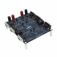
Figure 2. Si84xxCOM Evaluation Board
The evaluation board photo of Figure 2 shows the Silicon Labs Si844xx digital isolators placed at the center of the
board. The RS232 and 422/485 isolated transceivers are implemented with narrow-body, 2.5 kV Si8442AB and
Si8421BB digital isolators. The medical grade CAN bus interface is implemented with a wide-body Si8422AD
digital isolator rated at 5 kV.*
*Note: The creepage and clearance are defined by the narrow-body SOIC (2.5 kV) isolators used in the EVB and must NOT be
used for 5 kV isolation testing.
3. Required Equipment
Two dc power supplies (isolated)
Two red and black banana-to-banana cables
One straight-through RS232 cable (3'3, 2'2) (e.g.,. StarTech Model#MXT100_25)
One crossover (null modem) RS232 cable (3'2, 2'3) (Ex. StarTech Model # SCNM9FM)
One PC with COM1 port
Si84xxCOM evaluation board (board under test)
Si84xxCOM user's guide (this document)
3.1. Optional Equipment (User Can Test the Functionality of Standalone EVB Using the
Following Equipment)
One 4-channel oscilloscope, 250 MHz BW (e.g., TDS784A)
Dual output Pattern/Function generator, 80 MHz data rate (e.g., Agilent 81104A)
Two BNC to hook cable (e.g., Pomona #3788)
2
Rev. 0.1
�Si84xxCOM-EVB
4. Hardware Overview and Demo
The Si84xxCOM evaluation board operates from 4.75 to 5.25 V. Each isolated interface is enabled or disabled by
jumper option settings as shown in Figures 3, 4, and 5 (RS232, RS422/485 and CAN Bus isolated interfaces,
respectively).
Refer to Figure 3:
J3,J5
J9,J6
J15,J16
J1,J2
J4,J7,J8,J10
Refer to Figure 4:
Connector for +5 V bus (J3) and GND(J5) plane
Connector for +5VISO bus (J9) and ISOGND(J6) plane
Header 2x1, Supply for RS232 interface
DB9 Female (J1) and Male (J2) connector for RS232
Header 2x1, RS232 loopback test enable
J17, J18
J11,J12
RJ1,RJ2
Refer to Figure 5:
Header 2x1, Supply for RS422/485 interface
DB9 Female (J1) and Make (J2) connector for RS422/485
RJ45 connector for RS422/485
Header 2x1, Supply for CAN Bus interface
DB9 Female (J13) and Male (J14) connector for CAN bus
J19,J20
J13,J14
Figure 3. Power Supply Input and Isolated RS232 Interface
Rev. 0.1
3
�Si84xxCOM-EVB
Figure 4. Isolated 4-Wire R422/485 Interface
Figure 5. Isolated CAN Bus Interface
4.1. Common Board Setup
Perform the following steps for a common board setup:
1. Turn on the dc power supplies, and set the output voltage to 5.0 V, 500 mA current limit.
2. Connect red banana cables to each of the positive outputs of the power supply, and connect the black banana
cables to the respective negative or 0 V output.
3. Turn off the dc power supply.
4. Connect the other end of one of the red banana cables to J3 (+5 V) and the other end of the second red banana
cable to J9 (+5VISO).
5. Connect the other end of the black banana cable to J5 (GND) and J6 (ISOGND), respectively.
This completes the power supply connections to the board.
4
Rev. 0.1
�Si84xxCOM-EVB
4.2. Isolated RS232 interface Setup
Perform the following steps for an isolated RS232 interface setup:
1. Power up a PC with the COM1 port (Male DB9 connector).
2. Connect one end of the straight-through RS232 cable to the COM1 port and the other end to J1 of the
evaluation board. Table 1 lists the standard pin definitions of the interface.
Table 1. Isolated RS232 Pin Definitions
J1 DB9 (Female)
Pinout
RS232 Signal Name
J2 DB9 (Male)
Pinout
1,4,6,9
NC
1,4,6,9
2
RXD
2
3
TXD
3
5
GND
5
7
RTS
7
8
CTS
8
3. On the J2 side, use straight-through cable when connecting to DCE (Modem) and crossover cable when
connecting to DTE (PC, printers, PLCs etc). Refer to Figures 6 and 7.
4. Shunt jumpers J15 and J16 to apply power to the circuit.
5. Turn ON the dc power supply.
The board under test is ready to transfer datax.*
*Note: Most PCs support data rates up to 115 kbps, but the onboard transceiver and isolator can support a maximum data rate
of 1 Mbps.
Straight cable
Straight cable
J1
J2
Figure 6. DTE to DCE Connection
Rev. 0.1
5
�Si84xxCOM-EVB
�
Straight�cable
Crossover�cable�
��J1�
J2
Figure 7. DTE to DTE Connection
4.3. Isolated RS422/485 Interface Setup
The RS422 and RS485 standards are based on a balanced differential line. The RS422 interface is typically
implemented as a 4-wire, point-to-point communication system, whereas RS485 can be implemented in a 2-wire or
4-wire multipoint configuration.
Note: This EVB implements a full-duplex, isolated 4-wire RS422/RS485 interface with automatic flow control and should NOT
be used to implement a 2-wire interface
Please note that the RS422/485 standard does not recommend a specific connector or pinout like the RS232
standard. In light of this, the EVB has DB9 and 8-pin-RJ45 connectors for flexibility, allowing the user to choose
and follow the pinout definition table for proper cabling.
Proper termination is required at each end of the cable for reliable communication links and long wiring runs. The
EVB has place holders (RTERM1-4) for termination resistors to match the characteristic impedance of the cable
specified by the manufacturer. A typical value is around 120 . The RS422/RS485 transceivers used in the EVB
have 22 k (~0.5 UL) receiver input resistance and a fail-safe feature that guarantees the receiver output HIGH
when inputs are left open or shorted.
Perform the following steps for interface setup:
1. Turn off the dc power supplies (if they are not turned off already).
2. Shunt jumpers J17 and J18 to apply power to the circuit.
3. Refer to Table 2 for the RS422/485 connector pinout definition. Make sure the cable is made to this pinout
definition.
4. Recommended cables are 24 AWG 2 twisted pair with shield (e.g., Belden 9842-500).
5. A simple 4-wire master slave point-to-point connection is shown in Figure 8 for reference.
Connect the transmitter output of the master node to the receiver input (J12.1 and J12.2) of the EVB board.
Connect the transmitter output (J12.3 and J12.4) of the EVB to the receiver input of the master node.
Connect the isolated transmitter output (J11.1 and J11.2) of the EVB board to the receiver input of the slave
node. Connect the transmitter output of the slave node to the isolated receiver input (J11.4 and J11.3) of the
EVB.
6. Turn on the dc power supply.
7. The EVB is ready for data transfer and can support a maximum data rate of 52 Mbps.
6
Rev. 0.1
�Si84xxCOM-EVB
Table 2. RS422/485 Pinout Definition for DB9 and RJ45 Connector
J12
(Female DB9)
Pinout
RS422/485 Signal
Name
J11
(Male DB9) Pinout
RS422/485 Signal
Name
1
A (RxD+)
1
Y(TxD+)
2
B (RxD–)
2
Z(TxD–)
3
Z (TxD–)
3
B(RxD–)
4
Y (TxD+)
4
A(RxD+)
5
GND
5
GND
6,7,8,9
NC
6,7,8,9
NC
RJ1
Pinout
RS422/485 Signal
Name
RJ2
Pinout
RS422/485 Signal
Name
1,7,8
NC
1,7,8
NC
2
Y (TxD+)
2
A (RxD+)
3
Z (TxD–)
3
B(RxD–)
4
GND
4
GND
5
B (RxD–)
5
Z (TxD–)
6
A (RxD+)
6
Y (TxD+)
Master
Device
Y
Z
A
B
A
B
Y
Z
Y
Z
A
A
B
Y
B
Z
�
Slave
Device
Figure 8. Simple Point-to-Point RS422/485 Connection
Rev. 0.1
7
�Si84xxCOM-EVB
4.4. Isolated CAN Bus Interface Setup
CAN (Controller Area Network) Bus is a bidirectional, 2-wire (CANH and CANL) differential signaling bus with a
data rate up to 1 Mbps. The CAN bus signal has two states: recessive (logic High) and dominant (logic Low). When
no driver is active, the bus is in the recessive state (CANH=CANL). The non-bus side of the transceiver is
connected to a controller. The EVB implements an isolated controller-side CAN interface as shown in Figure 1. The
speed/slope control resistor RSPD is tied to GND for high-speed (1 Mbps) operation. Users can increase the value
of resistor RSPD for slower operation.
The CAN bus must be properly terminated at each end of the cable. The EVB comes with a standard termination of
120 (RTERM8) installed. The Si8422AD digital isolator powers up with default high output making sure the CAN
bus is in a recessive state.
Perform the following steps for interface setup:
1. Turn the power supply off, if it is not off already.
2. Shunt jumpers J19 and J20 to apply power to the circuit.
3. Standard twisted pair (24 AWG, ex HYCANBUS0901) with or without shield can be used. Refer to Table 3 for
pinout definition. Make sure the cable is made to this pinout definition.
4. A typical connection to the EVB is shown in Figure 9.
Connect the controller side driver output and receiver input to the J13.3 (DR) and J13.2 (RX) pins of EVB
respectively.
Connect the CANH (J14.7) and CANL (J14.2) of the EVB to the bus lines.
5. Turn on the dc power supply.
The EVB is ready for data transfer and can support a maximum data rate of 1 Mbps.
Table 3. CAN Bus Interface Pinout Definition
J13
(Female DB9)
Pinout
CAN Bus
Signal Name
J14
(Male DB9)
Pinout
CAN Bus
Signal Name
1,4,6,7,8,9
NC
1,4,5,6,8,9
NC
2
RX
(Receiver Output)
2
CANL
3
DR (Driver Input)
3,6
GND
5
GND
7
CANH
CAN Bus
Controller
CANH
DR
RX
BUS
CANL
Figure 9. Isolated CAN Bus Interface Connection
8
Rev. 0.1
�Si84xxCOM-EVB
5. Waveforms (tpdelay = Propagation Delay)
tpdelay
TxD
IsoTxD
Figure 10. Isolated RS232 Signal at 115 kbps
TxD
IsoTxD
Figure 11. Isolated RS232 Signal at 500 kbps
Rev. 0.1
9
�Si84xxCOM-EVB
A
B
IsoA
IsoB
Figure 12. Isolated RS422/485 Signals (Unterminated) at 10 Mbps
A
B
IsoA
IsoB
Figure 13. Isolated RS422/485 Signals (Unterminated) at 25 Mbps
10
Rev. 0.1
�Si84xxCOM-EVB
DR
CANH
CANL
RX
Figure 14. Isolated CAN Bus Signals (Terminated) at 1 Mbps
Rev. 0.1
11
�Figure 15. Isolated RS232 Interface Schematic
Si84xxCOM-EVB
6. Schematics
12
Rev. 0.1
�Figure 16. Isolated RS422/485 Interface Schematic
Si84xxCOM-EVB
Rev. 0.1
13
�Figure 17. Isolated CAN bus Interface Schematic
Si84xxCOM-EVB
14
Rev. 0.1
�Si84xxCOM-EVB
7. Si84xxCOM Bill Of Materials
(
Item Qty
1
1
2
1
3
1
4
1
5
2
6
11
)
Reference
Part Number
Manufacturer
J3
111-0702-001-ND
DIGIKEY
J9
111-0702-001-ND
DIGIKEY
J5
111-0703-001-ND
DIGIKEY
J6
111-0703-001-ND
DIGIKEY
C5 C11
C0805F104K4RACTU-ND DIGIKEY
C6 C14-20 C0805F104K4RACTU-ND DIGIKEY
C22 C24
C28
C2 C12
445-1357-1-ND
DIGIKEY
7
2
8
4
9
11
10
11
3
��
��
3
12
2
13
11
14
2
J4 J7-8
J10
J15-21
U3-4
15
16
17
18
1
2
4
1
U6
U1-2
MH1-4
RSPD
PCA82C251T/N3
MAX3232CSE+-ND
1902EK-ND/H546
P0.0ATR-ND
Linear
Technology
PHILIPS
MAXIM
DIGIKEY
DIGIKEY
19
1
RTERM8
RHM120AECT-ND
DIGIKEY
20
1
RPU1
P1.0KADTR-ND
DIGIKEY
21
2
RPU3-4
311-22KARTR-ND
DIGIKEY
22
4
RTERM1-4
23
1
RBIAS1
NO POP
DIGIKEY
24
1
RBIAS2
NO POP
DIGIKEY
25
2
RBIAS3-4
NO POP
DIGIKEY
26
1
IC2
Si8421BB-D-IS
Silicon Labs
27
1
IC1
Si8442AB-D-IS1
Silicon Labs
28
1
IC3
Si8422AD-B-IS
Silicon Labs
29
35
30
22
C29-32
C1 C3-4
C7-10 C13
C21 C23
C27
J1 J12-13
J2 J11
J14
RJ1-2
TP8-11
TP16-23
TP25-28
TP30
TP35-40
TP44-45
TP48-57
TP1-7
TP12-15
TP24 TP29
TP31-34
TP41-43
445-1357-1-ND
PCC2314CT-ND
DIGIKEY
Digikey
A35109-ND
DIGIKEY
A32092-ND
DIGIKEY
A31442-ND
DIGIKEY
S1011E-02-ND
LTC1686CS8#PBF-ND
12�323�
�
5000K-ND
DIGIKEY
DIGIKEY
DIGIKEY
Description
RED BANANA-JACK, RoHS.
RED BANANA-JACK, RoHS
BLACK BANANA-JACK, RoHS
BLACK BANANA-JACK , RoHS
CAP,0.1UF,X7R, 0805,16V,10% OR EQ, RoHS
CAP,0.1UF,X7R, 0805,16V,10% OR EQ, RoHS
CAP,0.47UF,X7R, 0805,16V,10% OR EQ,
RoHS
CAP,0.47UF,X7R, 0805,16V,10% OR EQ,
RoHS
CAP 1.0UF, X5R, CERAMIC, 0805, 16V,
10%, OR EQ, RoHS.
CONN, D-SUB PLUG, FEMALE, R/A, ANGLE,
9POS, 0.318MNT, RoHS.
CONN, D-SUB PLUG, MALE, R/A, ANGLE,
9POS, 0.318MNT, RoHS.
CONN, ETHERNET, RJ45-8 RIGHT ANGLE, OR
EQ, RoHS.
STAKE HEADER, 1X2, 0.1"CTR, GOLD, OR
EQ, RoHS..
5V RS422/485 TxRx, 52Mbps, SOIC8NB,
RoHS
IC, 5V, 1Mbps CAN TXRX, 8-SOIC, RoHS.
5V RS-232t TxRx, 1Mbps, SOIC16NB, RoHS
STAND OFF WITH SCREW, RoHS.
RES, 0 OHM, SMT, 0805, 1/8W,ᩋ1%, OR EQ,
RoHS.
RES, 120 OHM, SMT, 0805, 1/4W,ᩋ1%, OR
EQ, RoHS.
RES, 1.0K OHM, SMT, 0805, 1/4W,ᩋ5%, OR
EQ, RoHS.
RES, 22K OHM, SMT, 0805, 1/8W,ᩋ5%, OR
EQ, RoHS.
RES, NO POP OHM, SMT, 0805, 1/4W,ᩋ1%,
OR EQ, RoHS.
RES, NO POP, SMT, 0805, 1/8W, ᩋ5%, OR
EQ, RoHS.
RES, NO POP, 0805, 1/4W,ᩋ1%, OR EQ,
RoHS.
RES, NO POP, SMT, 0805, 1/4W,ᩋ1%, OR
EQ, RoHS.
2 Channel 2.5KV Digital Isolator,
150Mbps, SOIC8NB, RoHS
4 Channel 2.5KV Digital Isolator,
1Mbps, SOIC16NB, RoHS
2 Channel 5KV Digital Isolator,Default
High Ouput 1Mbps, SOIC16WB, RoHS
Test point
NO POP
Rev. 0.1
15
�Si84xxCOM-EVB
8. Ordering Guide
Table 4. Ordering Guide
16
Ordering Part
Number
Description
Si84xxCOM-RD
Isolated serial communication evaluation board
Rev. 0.1
�Si84xxCOM-EVB
NOTES:
Rev. 0.1
17
�Si84xxCOM-EVB
CONTACT INFORMATION
Silicon Laboratories Inc.
400 West Cesar Chavez
Austin, TX 78701
Tel: 1+(512) 416-8500
Fax: 1+(512) 416-9669
Toll Free: 1+(877) 444-3032
Please visit the Silicon Labs Technical Support web page:
https://www.silabs.com/support/pages/contacttechnicalsupport.aspx
and register to submit a technical support request.
The information in this document is believed to be accurate in all respects at the time of publication but is subject to change without notice.
Silicon Laboratories assumes no responsibility for errors and omissions, and disclaims responsibility for any consequences resulting from
the use of information included herein. Additionally, Silicon Laboratories assumes no responsibility for the functioning of undescribed features
or parameters. Silicon Laboratories reserves the right to make changes without further notice. Silicon Laboratories makes no warranty, representation or guarantee regarding the suitability of its products for any particular purpose, nor does Silicon Laboratories assume any liability
arising out of the application or use of any product or circuit, and specifically disclaims any and all liability, including without limitation consequential or incidental damages. Silicon Laboratories products are not designed, intended, or authorized for use in applications intended to
support or sustain life, or for any other application in which the failure of the Silicon Laboratories product could create a situation where personal injury or death may occur. Should Buyer purchase or use Silicon Laboratories products for any such unintended or unauthorized application, Buyer shall indemnify and hold Silicon Laboratories harmless against all claims and damages.
Silicon Laboratories and Silicon Labs are trademarks of Silicon Laboratories Inc.
Other products or brandnames mentioned herein are trademarks or registered trademarks of their respective holders.
18
Rev. 0.1
�