DATA SHEET
SKY13286-359LF: 0.1 to 6.0 GHz High Isolation SPDT
Absorptive Switch
Applications
GSM, PCS, WCDMA base stations
2.4 and 5.8 GHz ISM devices
Wireless local loops
J1
CBL
50
CBL
Features
50
CBL
J2
Small, QFN (16-pin, 4 x 4 mm) Pb-free package
(MSL1, 260 C per JEDEC J-STD-020)
Skyworks GreenTM products are compliant with
all applicable legislation and are halogen-free.
For additional information, refer to Skyworks
Definition of GreenTM, document number
SQ04–0074.
200570-001
Single, positive voltage control: 0 to 3 and 0 to 5 V
High isolation 64 dB at 1 GHz and 2 GHz
Integrated silicon CMOS driver
Absorptive
RFC
Decoder
VDD
VCTL
Figure 1. SKY13286-359LF Block Diagram
Description
The SKY13286-359LF is a GaAs pHEMT FET high-isolation,
absorptive switch. The device is an ideal component for base
station applications in which synthesizer isolation is critical.
The device is provided in a 4 x 4 mm, 16-pin Quad Flat No-Lead
(QFN) package. A functional block diagram is shown in Figure 1.
The pin configuration and package are shown in Figure 2. Signal
pin assignments and functional pin descriptions are provided in
Table 1.
Skyworks Solutions, Inc. • Phone [781] 376-3000 • Fax [781] 376-3100 • sales@skyworksinc.com • www.skyworksinc.com
200570K • Skyworks Proprietary Information • Products and Product Information are Subject to Change Without Notice • August 3, 2017
1
�GND
GND
GND
GND
DATA SHEET • SKY13286-359LF: SPDT ABSORPTIVE SWITCH
16
15
14
13
VDD
1
12
J1
VCTL
2
11
GND
RFC
3
10
GND
GND
4
9
J2
8
200570-002
GND
7
GND
6
GND
GND
5
Figure 2. SKY13286-359LF Pinout
(Top View)
Table 1. SKY13286-359LF Signal Descriptions
Pin
Name
Description
Pin
Name
Description
1
VDD
DC power supply
9
J2
RF output 2
2
VCTL
DC switch control pin. Switches insertion loss
state from RFC to J1 or J2 (see Table 5).
10
GND
Ground
3
RFC
RF input
11
GND
Ground
4
GND
Ground
12
J1
RF output 1
5
GND
Ground
13
GND
Ground
6
GND
Ground
14
GND
Ground
7
GND
Ground
15
GND
Ground
8
GND
Ground
16
GND
Ground
Electrical and Mechanical Specifications
The absolute maximum ratings of the SKY13286-359LF are
provided in Table 2. Recommended operating conditions are
specified in Table 3 and electrical specifications are provided in
Table 4.
Typical performance characteristics of the SKY13286-359LF are
illustrated in Figures 3 through 9.
The state of the SKY13286-359LF is determined by the logic
provided in Table 5.
Skyworks Solutions, Inc. • Phone [781] 376-3000 • Fax [781] 376-3100 • sales@skyworksinc.com • www.skyworksinc.com
2
August 3, 2017 • Skyworks Proprietary Information • Products and Product Information are Subject to Change Without Notice • 200570K
�DATA SHEET • SKY13286-359LF: SPDT ABSORPTIVE SWITCH
Table 2. SKY13286-359LF Absolute Maximum Ratings1
Parameter
Symbol
Minimum
Typical
Maximum
Units
5.5
V
Supply voltage
VDD
2.7
RF input power @ >500 MHz
VI
Operating temperature
TOP
–40
+95
C
Storage temperature
TSTG
–65
+150
C
1
W
1 Exposure to maximum rating conditions for extended periods may reduce device reliability. There is no damage to device with only one parameter set at the limit and all other parameters
set at or below their nominal value. Exceeding any of the limits listed here may result in permanent damage to the device.
ESD HANDLING: Although this device is designed to be as robust as possible, electrostatic discharge (ESD) can damage this device.
This device must be protected at all times from ESD when handling or transporting. Static charges may easily produce
potentials of several kilovolts on the human body or equipment, which can discharge without detection.
Industry-standard ESD handling precautions should be used at all times.
Table 3. Recommended Operating Conditions
Parameter
Symbol
Switching characteristics:
Rise, fall
Test Condition
Min
Typical
Max
Units
10/90% or 90/10% RF
30
ns
On/off
50% control to 90/10% RF
50
ns
Video feedthrough
TRISE = 3 ns, measurement bandwidth
= 500 MHz
25
mV
+23
+30
dBm
dBm
–80
dBm
+49
+47
+43
+46
dBm
dBm
dBm
dBm
Input power for 1 dB compression
PINPUT
VDD = 3V, 0.7-2.0 GHz
VDD = 5 V, 0.7-2.0 GHz
2nd harmonic
2fo
fO = 2400 MHz, PIN = –15 dBm
Third order intercept point
IP3
For 2-tone input power,
+8 dBm/tone, 1 MHz spacing:
VDD = 3.3 V, 0.7-1.0 GHz
VDD = 5.0 V, 0.7-1.0 GHz
VDD = 3.3 V, 1.0-2.0 GHz
VDD = 5.0 V, 1.0-2.0 GHz
+26
+45
+45
Control voltage:1
Low with VDD = 5 V
High with VDD = 5 V
VCTL_LOW
VCTL_HIGH
0
2.7
0.5
VDD
V
V
Low with VDD = 3.3 V
High with VDD = 3.3 V
VCTL_LOW
VCTL_HIGH
0
2.5
0.5
3.3
V
V
100
μA
Supply current
VDD = 5 V
Control current
VCTL = low or high
Supply voltage
μA
5
2.7
5.0
V
1 VDD must be applied before a Vctl high signal. A latch-up condition may occur if a logic high signal is applied before the VDD voltage. Control voltages switch the VDD voltage to the GaAs
switch.
Skyworks Solutions, Inc. • Phone [781] 376-3000 • Fax [781] 376-3100 • sales@skyworksinc.com • www.skyworksinc.com
200570K • Skyworks Proprietary Information • Products and Product Information are Subject to Change Without Notice • August 3, 2017
3
�DATA SHEET • SKY13286-359LF: SPDT ABSORPTIVE SWITCH
Table 4. SKY13286-359LF Electrical Specifications1
(VCTL = 0 V/3 V, VDD = 5 V, TOP = +25 C, PINPUT = 0 dBm, Characteristic Impedance [ZO] = 50 Ω, Unless Otherwise Noted)
Parameter
Symbol
Test Condition
Min
Typical
Max
Units
0.8
0.8
1.0
1.5
1.10
1.25
1.35
1.80
dB
dB
dB
dB
CW insertion loss
IL
0.1 to 2.0 GHz
2.0 to 3.0 GHz
3.0 to 4.0 GHz
4.0 to 6.0 GHz
Isolation
Iso
0.1 to 2.0 GHz
2.0 to 3.0 GHz
3.0 to 4.0 GHz
4.0 to 6.0 GHz
60
58
55
40
62
62
58
42
dB
dB
dB
dB
Return loss (insertion loss
state)2
RL
0.1 to 2.0 GHz
2.0 to 3.0 GHz
3.0 to 4.0 GHz
4.0 to 6.0 GHz
10
15
13
10
22
22
18
12
dB
dB
dB
dB
Return loss (isolation state) 2
RL
0.1 to 2.0 GHz
2.0 to 3.0 GHz
3.0 to 4.0 GHz
4.0 to 6.0 GHz
10
12
12
11
12
15
15
13
dB
dB
dB
dB
Insertion loss settling time
ΔIL
Insertion loss in db measured @ 1 μs
(referenced to a rising 10% RF level
on J1 & J2) minus the CW insertion
loss in dB. Freq = 2 GHz,
TOP = +25 °C, VCTL = 5 V,
pulse width = 1.15 ms, 50% duty
cycle.
0.40
dB
1 Performance is guaranteed only under the conditions listed in this table.
2 Lower frequency return loss is dependent on DC blocks.
Typical Performance Characteristics
(VCTL = 0 V/3 V, VDD = 5 V, TOP = +25 C, PIN = 0 dBm, Characteristic Impedance [Zo] = 50 Ω, Unless Otherwise Noted)
0
0
–0.5
–10
J1
J2
–20
–1.5
Isolation (dB)
–2.0
–2.5
–3.0
–30
–40
–50
–3.5
–60
–4.0
J1
J2
–4.5
200570-004
Insertion Loss (dB)
–1.0
–70
–5.0
–80
0
1
2
3
4
5
Frequency (GHz)
Figure 3. Insertion Loss vs Frequency
6
0
1
2
3
4
Frequency (GHz)
Figure 4. Isolation v s Frequency
Skyworks Solutions, Inc. • Phone [781] 376-3000 • Fax [781] 376-3100 • sales@skyworksinc.com • www.skyworksinc.com
4
August 3, 2017 • Skyworks Proprietary Information • Products and Product Information are Subject to Change Without Notice • 200570K
5
6
�DATA SHEET • SKY13286-359LF: SPDT ABSORPTIVE SWITCH
0
0
J1 |S11|
J2 |S11|
J1 |S22|
J2 |S22|
–5
–5
Return Loss (dB)
–20
–25
–30
J1 |S11|
J2 |S11|
J1 |S22|
J2 |S22|
–35
–40
–45
0
1
2
3
4
5
–10
–15
–20
–25
200570-006
–15
200570-005
Return Loss (dB)
–10
–30
6
0
1
2
Frequency (GHz)
4
5
6
Frequency (GHz)
Figure 5. Return Loss vs Frequency
(Insertion Loss State)
Figure 6. Return Loss vs Frequency
(Isolation State)
0
0
–10
–0.2
J1-J2
J2-J1
Insertion Loss (dB)
–20
–30
–40
–50
–60
3.0 V
3.3 V
5.0 V
–0.4
–0.6
–0.8
–1.0
–1.2
200570-007
–1.4
–70
–80
0
1
2
3
4
5
6
200570-008
Isolation (dB)
3
–1.6
–1.8
0
Frequency (GHz)
+4
+8
+12
+16
+20
+24
+28
+32
Input Power (dBm)
Figure 7. Output to Output Isolation
Figure 8. Insertion Loss vs Input Power Over Voltage
+55
+45
+40
0.7-1.0 GHz
1.0-2.0 GHz
+35
200570-009
IP3 (dBm)
+50
+30
2.8 3.0 3.2 3.4 3.6 3.8 4.0 4.2 4.4 4.6 4.8 5.0
Supply Voltage (V)
Figure 9. IP3 vs VDD Supply Voltage
Skyworks Solutions, Inc. • Phone [781] 376-3000 • Fax [781] 376-3100 • sales@skyworksinc.com • www.skyworksinc.com
200570K • Skyworks Proprietary Information • Products and Product Information are Subject to Change Without Notice • August 3, 2017
5
�DATA SHEET • SKY13286-359LF: SPDT ABSORPTIVE SWITCH
Table 5. SKY13286-359LF Truth Table
VCTL
RFC to J1
RFC to J2
0
Insertion loss
Isolation
1
Isolation
Insertion loss
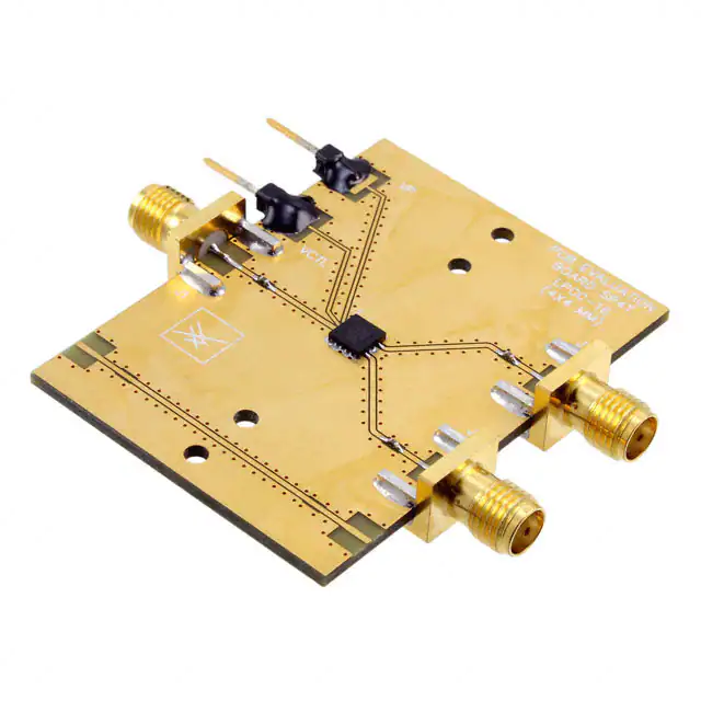
Evaluation Board Description
Package and Handling Information
The SKY13286-359LF Evaluation Board is used to test the
performance of the SKY13286-359LF SPDT absorptive switch. An
assembly drawing for the Evaluation Board is shown in Figure 10.
Instructions on the shipping container label regarding exposure to
moisture after the container seal is broken must be followed.
Otherwise, problems related to moisture absorption may occur
when the part is subjected to high temperature during solder
assembly.
Package Dimensions
The SKY13286-359LF is rated to Moisture Sensitivity Level 1
(MSL1) at 260 C. It can be used for lead or lead-free soldering.
For additional information, refer to the Skyworks Application Note,
Solder Reflow Information, document number 200164.
The PCB layout footprint for the SKY13286-359LF is shown in
Figure 11. Typical part markings are noted in Figure 12. Package
dimensions are shown in Figure 13, and tape and reel dimensions
are provided in Figure 14.
Care must be taken when attaching this product, whether it is
done manually or in a production solder reflow environment.
Production quantities of this product are shipped in a standard
tape and reel format.
GND
VP
VDD
J2
VCTL
J1
??
VCTL
1
RFC
??
J3
J1
CBLK
Through
??
CBL = 47 pF capacitor (5 places)
??
J2
Through
200570-010
Figure 10. SKY13286-359LF Evaluation Board Assembly Diagram
Skyworks Solutions, Inc. • Phone [781] 376-3000 • Fax [781] 376-3100 • sales@skyworksinc.com • www.skyworksinc.com
6
August 3, 2017 • Skyworks Proprietary Information • Products and Product Information are Subject to Change Without Notice • 200570K
�DATA SHEET • SKY13286-359LF: SPDT ABSORPTIVE SWITCH
8X 1.600
0.325 Typ
R0.200
Solderable Area
Pin 1
8X 1.600
2X 1.350
Package Outline
0.30
See Detail A
For Solderable Area
2X 1.350
Solderable Area
0.650 Pitch
0.55
Detail A
200570-011
Figure 11. SKY13286-359LF PCB Layout Footprint
Pin 1
Indicator
S286
XXXX
YWW
200570-012
Skyworks P/N
Skyworks GaAs Die Lot Number
Date Code
Y = Calendar Year
WW = Week
Figure 12. Typical Part Markings
Skyworks Solutions, Inc. • Phone [781] 376-3000 • Fax [781] 376-3100 • sales@skyworksinc.com • www.skyworksinc.com
200570K • Skyworks Proprietary Information • Products and Product Information are Subject to Change Without Notice • August 3, 2017
7
�DATA SHEET • SKY13286-359LF: SPDT ABSORPTIVE SWITCH
0.20 Ref
4.00
A
0.02 +0.03/–0.02
B
Seating
Plane
Pin 1
Indicator
2.70 +0.10/–0.15
1.35 +0.05/–0.075
Exposed Pad
Pin 1 Indicator
0.20 Min.
Typ.
0.65
4.00
0.325
2.70 +0.10/–0.15
1.35 +0.05/–0.075
2X
0.05 C
2X
0.40 ± 0.10
0.05 C
0.90 ± 0.10
0.30 ± 0.05
All dimensions are in millimeters
200570-013
Figure 13. SKY13286-359LF Package Dimensions
4.00 ± 0.10
0.30 ± 0.05 (T)
2.00 ± 0.05
∅1.50 +0.1/–0
8.00 ± 0.10
1.75 ± 0.10
B
A
B
∅1.50 Min.
R0.25 Typ.
1.10 ± 0.10 (Ko)
Detail B
4.35 ± 0.10 (Ao)
Notes:
1.
2.
3.
4.
Carrier tape material: black conductive polystyrene, non-bakeable
Cover tape material: transparent conductive HSA
Cover tape size: 9.2 mm width
ESD surface resistivity is ≥1 x 10⁵ ~ ≤ 1 x 10¹⁰ Ohms/square
per EIA, JEDEC TNR Specification.
Detail A
5. All measurements are in millimeters
200570-014
Figure 14. SKY13286-359LF Tape and Reel Dimensions
Skyworks Solutions, Inc. • Phone [781] 376-3000 • Fax [781] 376-3100 • sales@skyworksinc.com • www.skyworksinc.com
8
August 3, 2017 • Skyworks Proprietary Information • Products and Product Information are Subject to Change Without Notice • 200570K
12.00 ± 0.30
4.35 ± 0.10 (Bo)
A
5.50 ± 0.05
Pin 1
Indicator
�DATA SHEET • SKY13286-359LF: SPDT ABSORPTIVE SWITCH
Ordering Information
Model Name
SKY13286-359LF: SPDT Absorptive Switch
Manufacturing Part Number
SKY13286-359LF
Evaluation Board Part Number
SKY13286-359LF-EVB
Copyright © 2009, 2011-2014, 2017 Skyworks Solutions, Inc. All Rights Reserved.
Information in this document is provided in connection with Skyworks Solutions, Inc. (“Skyworks”) products or services. These materials, including the information contained herein, are provided by
Skyworks as a service to its customers and may be used for informational purposes only by the customer. Skyworks assumes no responsibility for errors or omissions in these materials or the
information contained herein. Skyworks may change its documentation, products, services, specifications or product descriptions at any time, without notice. Skyworks makes no commitment to
update the materials or information and shall have no responsibility whatsoever for conflicts, incompatibilities, or other difficulties arising from any future changes.
No license, whether express, implied, by estoppel or otherwise, is granted to any intellectual property rights by this document. Skyworks assumes no liability for any materials, products or
information provided hereunder, including the sale, distribution, reproduction or use of Skyworks products, information or materials, except as may be provided in Skyworks Terms and Conditions
of Sale.
THE MATERIALS, PRODUCTS AND INFORMATION ARE PROVIDED “AS IS” WITHOUT WARRANTY OF ANY KIND, WHETHER EXPRESS, IMPLIED, STATUTORY, OR OTHERWISE, INCLUDING FITNESS FOR A
PARTICULAR PURPOSE OR USE, MERCHANTABILITY, PERFORMANCE, QUALITY OR NON-INFRINGEMENT OF ANY INTELLECTUAL PROPERTY RIGHT; ALL SUCH WARRANTIES ARE HEREBY EXPRESSLY
DISCLAIMED. SKYWORKS DOES NOT WARRANT THE ACCURACY OR COMPLETENESS OF THE INFORMATION, TEXT, GRAPHICS OR OTHER ITEMS CONTAINED WITHIN THESE MATERIALS. SKYWORKS
SHALL NOT BE LIABLE FOR ANY DAMAGES, INCLUDING BUT NOT LIMITED TO ANY SPECIAL, INDIRECT, INCIDENTAL, STATUTORY, OR CONSEQUENTIAL DAMAGES, INCLUDING WITHOUT LIMITATION,
LOST REVENUES OR LOST PROFITS THAT MAY RESULT FROM THE USE OF THE MATERIALS OR INFORMATION, WHETHER OR NOT THE RECIPIENT OF MATERIALS HAS BEEN ADVISED OF THE
POSSIBILITY OF SUCH DAMAGE.
Skyworks products are not intended for use in medical, lifesaving or life-sustaining applications, or other equipment in which the failure of the Skyworks products could lead to personal injury,
death, physical or environmental damage. Skyworks customers using or selling Skyworks products for use in such applications do so at their own risk and agree to fully indemnify Skyworks for any
damages resulting from such improper use or sale.
Customers are responsible for their products and applications using Skyworks products, which may deviate from published specifications as a result of design defects, errors, or operation of
products outside of published parameters or design specifications. Customers should include design and operating safeguards to minimize these and other risks. Skyworks assumes no liability for
applications assistance, customer product design, or damage to any equipment resulting from the use of Skyworks products outside of stated published specifications or parameters.
Skyworks and the Skyworks symbol are trademarks or registered trademarks of Skyworks Solutions, Inc., in the United States and other countries. Third-party brands and names are for
identification purposes only, and are the property of their respective owners. Additional information, including relevant terms and conditions, posted at www.skyworksinc.com, are incorporated by
reference.
Skyworks Solutions, Inc. • Phone [781] 376-3000 • Fax [781] 376-3100 • sales@skyworksinc.com • www.skyworksinc.com
200570K • Skyworks Proprietary Information • Products and Product Information are Subject to Change Without Notice • August 3, 2017
9
�


 工商网监
湘ICP备2023018690号
工商网监
湘ICP备2023018690号