DATA SHEET
SKY16602-632LF: Low-Threshold PIN Diode Limiter
0.2 to 4.0 GHz
Applications
• Cellular infrastructure
• WLAN, WiMAX
• Receiver LNA protection
• Test instruments
Features
• Optimized for 0.2 to 4.0 GHz operation
• Low limiting threshold (+5 dBm typical)
Figure 1. SKY16602-632LF Block Diagram
• Low insertion loss
• Low distortion
Description
• Integrated PIN limiter and Schottky diodes, and DC blocks
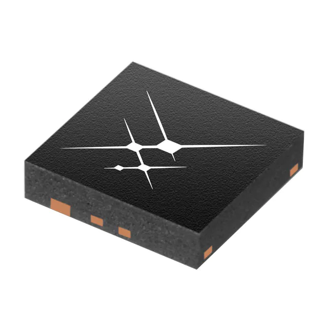
The SKY16602-632LF is a fully integrated PIN diode
low-threshold limiter module in a surface-mount package. It is
designed for use as a passive receiver protector in wireless or
other RF systems for frequencies up to 4 GHz. It features a low
limiting threshold, low-insertion loss, and low distortion in a Dual
Flat No Lead (DFN) package.
• DFN (2-pin, 2.3 x 2.3 mm) Pb-free package,
(MSL1, 260°C per JEDEC J-STD-020)
The SKY16602-632LF module is comprised of a PIN limiter diode,
a Schottky diode, and 2 DC blocking caps at the RF ports in a
2-lead DFN. The small package design reduces printed circuit
board area. The module can be tuned using external surface
mount technology (SMT) components for optimal narrow band
performance over the 0.2 to 4.0 GHz operating range.
The module can operate over the temperature range of -40 ˚C to
+85 ˚C.
A functional block diagram is shown in Figure 1. The pin
configuration and package are shown in Figure 2. Signal pin
assignments and functional pin descriptions are provided in
Table 1.
Skyworks Solutions, Inc. • Phone [781] 376-3000 • Fax [781] 376-3100 • sales@skyworksinc.com • www.skyworksinc.com
202945L • Skyworks Proprietary Information • Products and Product Information are Subject to Change Without Notice • November 11, 2021
1
�DATA SHEET ● SKY16602-632LF: LOW-THRESHOLD PIN DIODE LIMITER
Figure 2. SKY16602-632LF Pinout
(Top View)
Table 1. SKY16602-632LF Signal Descriptions
Pin
Name
Description
1
RF_IN
RF input, AC coupled
2
RF_OUT
RF output, AC coupled
3
GND
Must be connected to chassis ground
4
PAD
Exposed pad (must be isolated from ground)
Skyworks Solutions, Inc. • Phone [781] 376-3000 • Fax [781] 376-3100 • sales@skyworksinc.com • www.skyworksinc.com
202945L • Skyworks Proprietary Information • Products and Product Information are Subject to Change Without Notice • November 11, 2021
2
�DATA SHEET ● SKY16602-632LF: LOW-THRESHOLD PIN DIODE LIMITER
Electrical and Mechanical Specifications
The absolute maximum ratings of the SKY16602-632LF are
provided in Table 2. Electrical specifications for the un-tuned
limiter module are provided in Table 3, and typical performance
characteristics start at Figure 4. Electrical specifications for the
2.45 GHz tuned limiter module are provided in Table 4.
Figure 8 shows the power derating curve for the limiter. The
temperature is referenced to the bottom of the DFN package.
Table 2. SKY16602-632LF Absolute Maximum Ratings1
Parameter
Symbol
Minimum
Maximum
Unit
RF input power (CW) at TCASE = 120°C, without external tune
PIN
1
W
RF input power (1 μs pulse, 10% duty cycle) at TCASE = 120°C, without external tune
PIN
10
W
CW power dissipation at TCASE = 120°C
PDIS
0.4
W
Storage temperature
TSTG
-65
+150
°C
Operating temperature
TOP
-40
+85
°C
1000
250
150
V
V
V
Electrostatic discharge:
Charged-Device Model (CDM), Class 4
Human Body Model (HBM), Class 1B
Machine Model (MM), Class A
ESD
1 Exposure to maximum rating conditions for extended periods may reduce device reliability. There is no damage to device with only one parameter set at the limit and all other parameters set at or
below their nominal value. Exceeding any of the limits listed here may result in permanent damage to the device.
ESD HANDLING: Industry-standard ESD handling precautions must be adhered to at all times to avoid damage to this device.
Table 3. SKY16602-632LF Electrical Specifications (Untuned Circuit, Reference Figure 1)
(TOP = 25°C, ZO = 50 Ω, as Measured in Skyworks Evaluation Board Optimized for Operation at 0.2 to 4.0 GHz, Unless Otherwise Noted)
Parameter
Symbol
Condition
Frequency
Min
Typ
Max
Units
Reverse voltage
VR
20
V
Forward current
IF
50
mA
Insertion loss
IL
PIN = 0 dBm
0.90 GHz
0.3
0.5
dB
Return loss
RL
PIN = 0 dBm
0.90 GHz
14
Threshold level
TL
P1dB
0.90 GHz
Saturated CW input power1
PIN_CW
Flat leakage power2
FL
Recovery time3
tR
Thermal resistance
θJC
PIN = +10 dBm
5.3
6.0
dB
6.7
dBm
0.90 GHz
30
dBm
0.90 GHz
6
dBm
0.90 GHz
5
ns
55
°C/W
Junction-to-case
1 Saturated CW input power is defined as the point where the diode series resistance does not change with the rectified current. As the input power increases past this point, output power will
increase until the diode reaches its max power limit.
2 Flat leakage power is defined as the power level after the limiter has fully turned on and the output pulse reaches a constant level.
3 Recovery time represents the transition time from the high-loss to low-loss state following the removal of high-power input. RF pulse modulation: 1 μs pulse width and 0.1% duty factor.
Skyworks Solutions, Inc. • Phone [781] 376-3000 • Fax [781] 376-3100 • sales@skyworksinc.com • www.skyworksinc.com
202945L • Skyworks Proprietary Information • Products and Product Information are Subject to Change Without Notice • November 11, 2021
3
�DATA SHEET ● SKY16602-632LF: LOW-THRESHOLD PIN DIODE LIMITER
Theory of Operation
Tuned Circuit
A limiter prevents overload by allowing RF signals that are
below a certain threshold to pass through, but larger signals
exceeding the threshold are increasingly attenuated. The
SKY16602-632LF has a lower threshold level over a traditional
self-bias limiter circuit with an inductor for a ground return. It
accomplishes this by adding a basic PIN limiter diode (pin 1) in
parallel to a Schottky diode (pin 2). The low turn on voltage of
the Schottky diode reduces the threshold level while the PIN
limiter diode protects the Schottky diode at higher power levels.
Therefore, for maximum RF power handling, the RF input signal
is required to be connected to Pin 1. The two internal DC
input/output capacitors provide DC blocking needed for most
applications.
The module may be RF tuned for optional RF match and
insertion loss centered at a target frequency within its normal
band of operation. This is done with the use of external surface
mount components. The schematic diagram in Figure 3 shows
the SKY16602-632LF limiter with a shunt connected capacitor
and inductor tuned for 2.45 GHz. The Bill of Materials for the
2.45 GHz tuned circuit is shown in Table 4.
Electrical specifications for the 2.45 GHz tuned limiter module
are provided in Table 5.
For additional target frequencies, refer to Table 6 for inductor
and capacitor values.
Figure 3. SKY16602-632LF Schematic
with External Tuning Networks Optimized for 2.45 GHz
Skyworks Solutions, Inc. • Phone [781] 376-3000 • Fax [781] 376-3100 • sales@skyworksinc.com • www.skyworksinc.com
202945L • Skyworks Proprietary Information • Products and Product Information are Subject to Change Without Notice • November 11, 2021
4
�DATA SHEET ● SKY16602-632LF: LOW-THRESHOLD PIN DIODE LIMITER
Table 4. Evaluation Board Bill of Materials for EN33-D946-001 (2.45 GHz Tuned Circuit)
Component
Value
Size
Manufacturer
Mfr. Part Number
Characteristics
C1
15 pF
0402
Murata
GRM1555C1H150J
C0G, 50 V
L1
2.2 nH
0402
Taiyo Uden
HK10052N2S
300 mA, R = 0.13 Ω
Table 5. SKY16602-632LF Electrical Specifications (Tuned to 2.45 GHz Operation, Reference Figure 3)
(TOP = 25°C, ZO = 50 Ω, as Measured in Skyworks Evaluation Board Optimized for Operation at 2.45 GHz, Unless Otherwise Noted)
Parameter
Symbol
Condition
Frequency
Min
Typ
Max
Units
Insertion loss
IL
PIN= 0 dBm
2.45 GHz
0.5
dB
Return loss
RL
PIN= 0 dBm
2.45 GHz
25
dB
Threshold level
TL
P1dB
2.45 GHz
5
dBm
Saturated CW input power1
PIN_CW
2.45 GHz
23
dBm
Flat leakage power2
FL
PIN = +10 dBm
2.45 GHz
4
dBm
Input third order intercept
IIP3
PIN = -10 dBm/tone, spacing = 10 MHz
2.45 GHz
21
dBm
Recovery time3
tR
2.45 GHz
5
ns
Thermal resistance
θJC
55
°C/W
Junction to case
1 Saturated CW input power is defined as the point where the diode series resistance does not change with the rectified current. As the input power increases past this point, output power will
increase until the diode reaches its max power limit.
2 Flat leakage power is defined as the power level after the limiter has fully turned on and the output pulse reaches a constant level.
3 Recovery time represents the transition time from the high-loss to low-loss state following the removal of high-power input. RF pulse modulation: 1 μs pulse width and 0.1% duty factor.
Table 6. Bill of Materials for EN33-D946-001 Tuned Circuit
Frequency
(GHz)
L
(nH)
C
(pF)
Frequency
(GHz)
L
(nH)
C
(pF)
Frequency
(GHz)
L
(nH)
C
(pF)
1.06
12
15
1.55
5.6
10
2.50
1.8
15
1.16
12
4.7
1.57
6.8
4.7
2.60
1.8
9
1.22
10
15
1.68
4.7
47
2.90
1.5
5.6
1.22
10
12
1.70
4.7
22
2.95
1.5
5
1.23
10
12
1.75
4.7
10
3.05
1.4
5
1.29
10
10
1.85
4.7
5.6
3.50
1
4.7
1.35
9
10
1.90
4.7
4.7
3.63
1
3.6
1.40
8
13
2.40
2
15
4.30
0.7
1.8
1.45
6.8
10
2.45
2.2
15
4.50
0.3
1.8
Skyworks Solutions, Inc. • Phone [781] 376-3000 • Fax [781] 376-3100 • sales@skyworksinc.com • www.skyworksinc.com
202945L • Skyworks Proprietary Information • Products and Product Information are Subject to Change Without Notice • November 11, 2021
5
�DATA SHEET ● SKY16602-632LF: LOW-THRESHOLD PIN DIODE LIMITER
Typical Performance Characteristics
(TOP=25 °C, Characteristic Impedance = 50 Ω)
0
–4
–6
–8
–10
202945E-005
Insertion Loss (dB)
–2
–12
–14
–16
–10
–5
0
+5
+10
+15
+20
+25
+30
Power In (dBm)
Figure 4. Small Signal Performance without External Tuning
Figure 5. Insertion Loss vs CW Input Power at 0.90 GHz
without External Tuning
Figure 6. Small Signal Performance with External Tuning
Networks Optimized for 2.45 GHz
Figure 7. Insertion Loss vs CW Input Power
at 2.45 GHz (Tuned Circuit)
Figure 8. Power Derating Curve (Pdiss = 0.95 W) vs
Temperature on Bottom of Package Leadframe
Without External Tune
Skyworks Solutions, Inc. • Phone [781] 376-3000 • Fax [781] 376-3100 • sales@skyworksinc.com • www.skyworksinc.com
202945L • Skyworks Proprietary Information • Products and Product Information are Subject to Change Without Notice • November 11, 2021
6
�DATA SHEET ● SKY16602-632LF: LOW-THRESHOLD PIN DIODE LIMITER
Evaluation Board Description
Package and Handling Information
The SKY16602-632LF Evaluation Boards are used to test the
performance of the limiter. Assembly drawings for the
Evaluation Boards are shown in Figures 9 and 10. The
Evaluation Board layer detail is provided in Figure 11.
Instructions on the shipping container label regarding exposure
to moisture after the container seal is broken must be followed.
Otherwise, problems related to moisture absorption may occur
when the part is subjected to high temperature during solder
assembly.
Package Dimensions
The SKY16602-632LF is rated to Moisture Sensitivity Level 1
(MSL1) at 260 °C. It can be used for lead or lead-free soldering.
For additional information, refer to the Skyworks Application
Note, Solder Reflow Information, document number 200164.
The PCB layout footprint for the SKY16602-632LF is shown in
Figure 12. Typical part markings are noted in Figure 13.
Package dimensions are shown in Figure 14, and tape and reel
dimensions are provided in Figure 15.
Care must be taken when attaching this product, whether it is
done manually or in a production solder reflow environment.
Production quantities of this product are shipped in a standard
tape and reel format.
Figure 9. SKY16602-632LF Evaluation Board Assembly Diagram
Figure 10. SKY16602-632LF Evaluation Board Assembly Diagram (Tuned Circuit)
Skyworks Solutions, Inc. • Phone [781] 376-3000 • Fax [781] 376-3100 • sales@skyworksinc.com • www.skyworksinc.com
202945L • Skyworks Proprietary Information • Products and Product Information are Subject to Change Without Notice • November 11, 2021
7
�DATA SHEET ● SKY16602-632LF: LOW-THRESHOLD PIN DIODE LIMITER
Figure 11. Board Layer Detail Physical Characteristics
Skyworks Solutions, Inc. • Phone [781] 376-3000 • Fax [781] 376-3100 • sales@skyworksinc.com • www.skyworksinc.com
202945L • Skyworks Proprietary Information • Products and Product Information are Subject to Change Without Notice • November 11, 2021
8
�DATA SHEET ● SKY16602-632LF: LOW-THRESHOLD PIN DIODE LIMITER
Figure 12. SKY16602-632LF PCB Layout Footprint
Figure 13. SKY16602-632LF Typical Part Markings
Skyworks Solutions, Inc. • Phone [781] 376-3000 • Fax [781] 376-3100 • sales@skyworksinc.com • www.skyworksinc.com
202945L • Skyworks Proprietary Information • Products and Product Information are Subject to Change Without Notice • November 11, 2021
9
�DATA SHEET ● SKY16602-632LF: LOW-THRESHOLD PIN DIODE LIMITER
Figure 14. SKY16602-632LF Package Dimensions
Figure 15. SKY16602-632LF Tape and Reel Dimensions
Skyworks Solutions, Inc. • Phone [781] 376-3000 • Fax [781] 376-3100 • sales@skyworksinc.com • www.skyworksinc.com
202945L • Skyworks Proprietary Information • Products and Product Information are Subject to Change Without Notice • November 11, 2021
10
�DATA SHEET ● SKY16602-632LF: LOW-THRESHOLD PIN DIODE LIMITER
Ordering Information
Part Number
Product Description
Evaluation Board Part Number
SKY16602-632LF
Low-Threshold PIN Diode Limiter EVB
SKY16602-632EK1
SKY16602-632LF
Low-Threshold PIN Diode Limiter Tunable EVB
SKY16602-632EK2
Copyright © 2013-2014, 2016-2021 Skyworks Solutions, Inc. All Rights Reserved.
Information in this document is provided in connection with Skyworks Solutions, Inc. (“Skyworks”) products or services. These materials, including the information contained herein, are provided by
Skyworks as a service to its customers and may be used for informational purposes only by the customer. Skyworks assumes no responsibility for errors or omissions in these materials or the
information contained herein. Skyworks may change its documentation, products, services, specifications or product descriptions at any time, without notice. Skyworks makes no commitment to
update the materials or information and shall have no responsibility whatsoever for conflicts, incompatibilities, or other difficulties arising from any future changes.
No license, whether express, implied, by estoppel or otherwise, is granted to any intellectual property rights by this document. Skyworks assumes no liability for any materials, products or
information provided hereunder, including the sale, distribution, reproduction or use of Skyworks products, information or materials, except as may be provided in Skyworks’ Terms and Conditions
of Sale.
THE MATERIALS, PRODUCTS AND INFORMATION ARE PROVIDED “AS IS” WITHOUT WARRANTY OF ANY KIND, WHETHER EXPRESS, IMPLIED, STATUTORY, OR OTHERWISE, INCLUDING FITNESS FOR A
PARTICULAR PURPOSE OR USE, MERCHANTABILITY, PERFORMANCE, QUALITY OR NON-INFRINGEMENT OF ANY INTELLECTUAL PROPERTY RIGHT; ALL SUCH WARRANTIES ARE HEREBY EXPRESSLY
DISCLAIMED. SKYWORKS DOES NOT WARRANT THE ACCURACY OR COMPLETENESS OF THE INFORMATION, TEXT, GRAPHICS OR OTHER ITEMS CONTAINED WITHIN THESE MATERIALS. SKYWORKS
SHALL NOT BE LIABLE FOR ANY DAMAGES, INCLUDING BUT NOT LIMITED TO ANY SPECIAL, INDIRECT, INCIDENTAL, STATUTORY, OR CONSEQUENTIAL DAMAGES, INCLUDING WITHOUT LIMITATION,
LOST REVENUES OR LOST PROFITS THAT MAY RESULT FROM THE USE OF THE MATERIALS OR INFORMATION, WHETHER OR NOT THE RECIPIENT OF MATERIALS HAS BEEN ADVISED OF THE
POSSIBILITY OF SUCH DAMAGE.
Skyworks products are not intended for use in medical, lifesaving or life-sustaining applications, or other equipment in which the failure of the Skyworks products could lead to personal injury,
death, physical or environmental damage. Skyworks customers using or selling Skyworks products for use in such applications do so at their own risk and agree to fully indemnify Skyworks for any
damages resulting from such improper use or sale.
Customers are responsible for their products and applications using Skyworks products, which may deviate from published specifications as a result of design defects, errors, or operation of
products outside of published parameters or design specifications. Customers should include design and operating safeguards to minimize these and other risks. Skyworks assumes no liability for
applications assistance, customer product design, or damage to any equipment resulting from the use of Skyworks products outside of Skyworks’ published specifications or parameters.
Skyworks, the Skyworks symbol, Sky5®, SkyOne®, SkyBlue™, Skyworks Green™, Clockbuilder®, DSPLL®, ISOmodem®, ProSLIC®, and SiPHY® are trademarks or registered trademarks of
Skyworks Solutions, Inc. or its subsidiaries in the United States and other countries. Third-party brands and names are for identification purposes only and are the property of their respective
owners. Additional information, including relevant terms and conditions, posted at www.skyworksinc.com, are incorporated by reference.
Skyworks Solutions, Inc. • Phone [781] 376-3000 • Fax [781] 376-3100 • sales@skyworksinc.com • www.skyworksinc.com
202945L • Skyworks Proprietary Information • Products and Product Information are Subject to Change Without Notice • November 11, 2021
11
�