AEK-USB-2TYPEC1
Data brief
USB Type-C™ and Power Delivery dual port interface board with automotivegrade STUSB1702Y USB Type-C controller
Features
•
•
•
•
Both ports acting as Provider role
Type-C attach and cable orientation detection
High voltage protections on VBUS and CC lines
VBUS switch gate drivers
•
VBUS monitoring and discharge path
•
•
•
•
A current sensing circuit for each port on VBUS line
Power connector to interface with external power boards (not included)
Total board dimensions: 85 mm x 81 mm
RoHS compliant
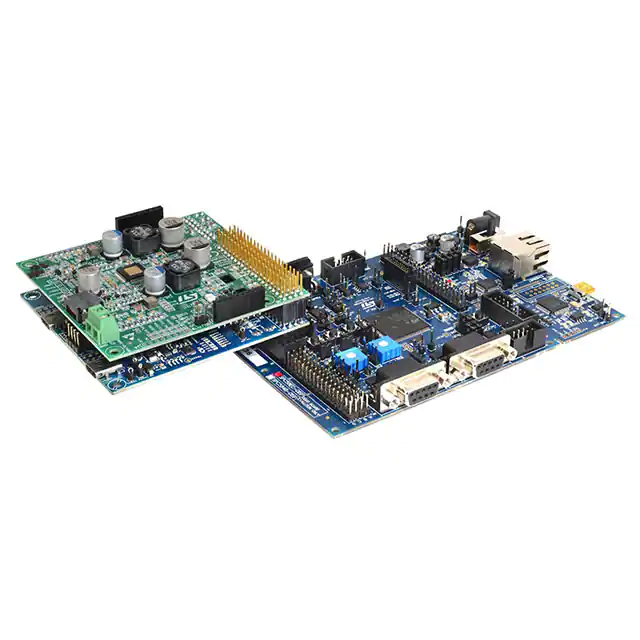
Description
The AEK-USB-2TYPEC1 automotive grade USB Type-C and Power Delivery dual
port expansion board is part of the ST AutoDevKit development initiative. It embeds
two STUSB1702Y USB Type-C™ port controllers for a two-port Provider solution.
Each STUSB1702Y USB Type-C port controller includes a fully-featured USB type-C
state machine for attach/detach and cable orientation detection, a USB PD PHY and
BMC transceiver, high voltage (20 V) technology VBUS voltage monitoring, 600 mA
VCONN power switch, VBUS and VCONN discharge paths, 22 V CC line protection,
VBUS switch gate drivers and data role configuration (not used in this case).
Product summary
dual-port USB Type-C
function board
AEKUSB-2TYPEC1
evaluation kit with
dual-port USB Type-C
function board and
SPC58 Chorus
discovery board
AEKDUSBTYPEC1
automotive grade USB
Type-C controller (with
STUSB1702Y
Tx/Rx line driver and
BMC)
firmware package for
the AEKDUSBTYPEC1 kit
STSWUSB2TYPEC1
The two USB Type-C ports have USB 2.0 data lines that are accessible through onboard connectors J101 and J102. The same connectors may be used to redirect the
data from one of the two USB 2.0 ports to the 4x20 pass-through connector.
The board also has a power status LED and three status LEDs to signal what each
Type-C port is advertising: power role, VBUS negotiation status and CC line
orientation (direct or flipped). Two alternate function connectors (not mounted) are
available for extension or future developments.
The AEK-USB-2TYPEC1 board is designed to be connected to a SPC58 Chorus
4 MB flash discovery board (SPC58EC-DISP) equipped with a 32-bit Power
Architecture® microcontroller for automotive ASIL-B applications. The AEKDUSBTYPEC1 kit consists of two boards and a USB-PD firmware package, so you can
develop application based on the USB-PD Provider role.
The AEK-USB-2TYPEC1 embeds a connector for an external power board, which
would allow the system to deliver output voltage profiles up to 20 V and satisfy
various power requests according to the USB Power Delivery specification.
DB3626 - Rev 1 - September 2018
For further information contact your local STMicroelectronics sales office.
www.st.com
�AEK-USB-2TYPEC1
AEK-USB-2TYPEC1 schematics
1
AEK-USB-2TYPEC1 schematics
Figure 2. AEK-USB-2TYPEC1 board schematic 1 - block diagram
USBD0[0..1]
VREG_0
Connectors
R1
47k N.M.
Type-C controller Port 0
USBD0_[0..1]
I2C_SDA
I2C_SCL
I2C_SDA
I2C_SCL
CS_0
SCK_0
MOSI_0
MISO_0
USBD[0..1]
R2
47k
CS
SCLK
MOSI
MISO
TX_EN_0
ALERT#_0
TX_EN
ALERT#
RESET_0
RESET
I_SENSE_0
V_SENSE_0
I
V
Power Supply
VBUS_OUT_0
CC1
CC1
CC2
CC2
I_SENSE
V_SENSE
I_SENSE
V_SENSE
VBUS_IN
VCONN
I2C_SCL
I2C_SDA
I2C_SCL
I2C_SDA
Type-C connector Port 0
ADDR0
VBUS
VBUS_OUT
03_Type-C_Controller_Port_0
04_Type-C_Connector_Port_0
VCONN_OUT_0
VREG_1
VBUS_0
VBUS_1
VCONN
VBUS_IN_0
VBUS_IN_1
VCONN_OUT_1
VCONN_IN
VBUS_OUT_1
VCONN
VBUS_IN
Type-C Connector Port 1
ADDR0
USBD[0..1]
R4
47k N.M.
CS
SCLK
MOSI
MISO
CS_1
SCK_1
MOSI_1
MISO_1
USBD1_[0..1]
R3
47k
Type-C controller Port 1
02_Power_Supply
TX_EN_1
ALERT#_1
TX_EN
ALERT#
RESET_1
RESET
I_SENSE_1
V_SENSE_1
CC1
CC2
I_SENSE
V_SENSE
I
V
I2C_SDA
I2C_SCL
CC1
CC2
I_SENSE
V_SENSE
VBUS
VBUS_OUT
I2C_SDA
I2C_SCL
06_Type-C_controller_Port_1
07_Type-C_Connector_Port_1
01_Connectors
USBD1[0..1]
Figure 3. AEK-USB-2TYPEC1 board schematic 2 - connectors
J102
CONN_SPC5_CD20x2
J101
CONN_SPC5_AB20x2
0
R134
0
PF12
PF13
MOSI1
PF1
PI5
PG3
LED02
LED03
PG4
USB_PIN_1
PE0
TXEN0
TXEN1
PE3
USB_PIN_2
ALERT1
PI2
ALERT0
PM14
PG15
PD2
PA10
PA0
PF0
PE7
I2C_SCL
MISO1
PG14
PC14
LED12
PI3
PI6
SCK1
PD13
PG5
USB_PIN_3
LED13
PG12
PG10
USB_PIN_4
MISO0
PD5
NSS0
PE8
V_SENSE_0
I_SENSE_0
SCK0
V_SENSE_1
RESET0
PF14
PA3
PC7
PK1
PI7
PG11
PG6
PB6
PD8
I_SENSE_1
MOSI0
PE15
+5V
NSS1
SCK1
MOSI1
MISO1
ALERT1
RESET1
DB3626 - Rev 1
VCONN
+VSYS
TP101
TEST POINT
TP102
TEST POINT
R111
JP101
USB_D
0
ALERT#_0
R113
+3V3
0
R122
0
TX_EN_1
CS_1
R125
0
R129
0
R130
0
R131
0
R132
0
USBD_1
USBD0_1
USBD1_1
USBD_1
JP102
USB_D
0
RESET_0
R118
1
2
3
4
SCK_1
LED01
+3V3
0 N.M
R119
0 N.M
R123
0 N.M
R126
0 N.M
USB_PIN_1
USB_PIN_2
USB_PIN_3
USB_PIN_4
R116
0 N.M
TP104
TEST POINT
R120
0 N.M
R124
0 N.M
R127
0 N.M
USBD_1
TP105
TEST POINT
R108
110
R110
110
R112
680
R114
110
R117
110
R121
680
R128
110
ROLE
D101
BLUE LED
D102
GREEN LED
D103
ORANGE LED
+5V
TP103
TEST POINT
LED02
LED03
LED11
R115
USBD_0
R102
2.2k
I2C_SDA
DP
1
2
3
4
I2C pull-up
+VSYS
R101
2.2k
Por t 0
MISO_0
+VEXT
PE2
PD4
PM2
1
USBD_0
USBD0_0
USBD1_0
USBD_0
MOSI_0
VBUS_0
0
VCONN
SCK_0
DM
J103
Power Connector 9x2
VBUS_0
2
VBUS_0
6
VBUS_0
4
VBUS_0
8
10
12
14
16
18
1
RESET1
Por t 1
TXEN1
0
NSS1
PL8
1
RESET0
R109
PD12
PH1
PG2
PI4
PG9
PB7
1
3
5
7
9
11
13
15
17
LED12
LED13
VBUS
CC
ROLE
VBUS
CC
D104
BLUE LED
D105
GREEN LED
D106
ORANGE LED
D107
BLUE LED
MOSI_1
+VSYS
MISO_1
USBD1_[0..1]
USBD0_[0..1]
USBD0_[0..1]
ALERT#_1
RESET_1
USER LEDS
USBD1_[0..1]
USBD1_1
ALERT0
0
USBD1_0
MISO0
0
R107
R105
1k
USBD0_1
MOSI0
CS_0
R106
VBUS_1
VBUS_1
VBUS_1
VBUS_1
VBUS_1
PF2
PB11
PC2
PA3
I2C_SCL
+VSYS
TX_EN_0
USBD0_0
SCK0
0
0
RX & TX Signals
NSS0
R103
R104
D1
D2
D3
D4
D5
D6
D7
D8
D9
D10
D11
D12
D13
D14
D15
D16
D17
D18
D19
D20
VOLTAGE TESTPOINTS
USB 2.0
TXEN0
C1
C2
C3
C4
C5
C6
C7
C8
C9
C10
C11
C12
C13
C14
C15
C16
C17
C18
C19
C20
1
R133
B1
B2
B3
B4
B5
B6
B7
B8
B9
B10
B11
B12
B13
B14
B15
B16
B17
B18
B19
B20
1
LED01
LED11
A1
A2
A3
A4
A5
A6
A7
A8
A9
A10
A11
A12
A13
A14
A15
A16
A17
A18
A19
A20
PD1
PA11
PI8
PF11
1
I2C_SDA
page 2/8
�AEK-USB-2TYPEC1
AEK-USB-2TYPEC1 schematics
Figure 4. AEK-USB-2TYPEC1 board schematic 3 - power supply
+VSYS
+VEXT
+5V
R207 0
VCONN_OUT_0
R206 0 N.M.
+3V3
VCONN_OUT_1
+5V
+5V
C204
10µF
VBUS_IN_0
R201
10k
JP202
VCONN
VBUS_IN_1
Q203
STL9P3LLH6
8
1
7
2
6
3
5
D201
SM4T26AY
+5V
R202
10k
4
C205
10µF
4
+5V
JP201
VCONN
VBUS_OUT_0
Q202
STL9P3LLH6
1
8
2
7
3
6
5
Q201
STL9P3LLH6
1
8
2
7
3
6
5
3
2
1
C202
100nF N.M.
0
ST
C206
10µF
R203
10k
VBUS_OUT_1
Q204
STL9P3LLH6
1
8
2
7
3
6
5
R204
10k
1
ST
C207
10µF
C208
10µF
1
7
2
1
5
6
7
2
1
5
6
0
Q206
Q205
JP204
VBUS_5V_nEN
STL6N2VH5
3
The power board plugged on top
of the Type-C expansion board
will close this jumper
4
8
1
2
STL6N2VH5
3
1
2
4
8
JP203
VBUS_5V_nEN
The power board plugged on top
of the Type-C expansion board
will close this jumper
D202
SM4T26AY
4
C203
10µF N.M
R205 0
2
VOUT
3
2
1
C201
100nF
VIN
VCONN_IN
4
3
GND
R208 0 N.M.
U201
LD1117A
1
+VEXT
TP301
TEST POINT
TP302
TEST POINT
1
1
Figure 5. AEK-USB-2TYPEC1 board schematic 4 - Type-C control port 0
VBUS_OUT
VDD
VBUS_IN
R301
21k
CC2
CC1
Q302
STD28P3LLH6AG
Q301
STD28P3LLH6AG
VBUS_OUT
R302
21k
TP303
TEST POINT N.M.
1
STD28P3LLH6AG
Q303
+VSYS
R303
10k
V_SENSE
TP304
TEST POINT N.M.
EN_SRC
VREG_0
EN_SNK
1
C301
1uF
0
C302
1uF
C303
1uF
TP306
TEST POINT N.M.
I_SENSE
I
R304
10k
R305
820
1
V
EN_SRC
EN_SNK
ADDR0
VBUS_OUT
R307
10k
TP305
TEST POINT N.M.
+VSYS
17
16
SCLK
15
TX_EN
14
R308
10k N.M.
MISO
13
ADDR0
10k
R310
NSS
12
11
10
25
MOSI
RESET
GND
MISO
18
+VSYS
1
20
19
VBUS_EN_SNK
VBUS_EN_SRC
23
22
21
VREG_1V2
VDD
CC2DB
SDA
R309
10k
+VSYS
TX_EN
CC2
SCL
6
RESET
SCLK
ALERT#
5
R306
2.2k
VBUS_SENSE
VCONN
8
4
CC2
CC2
+VSYS
A_B_SIDE
CC1
9
3
Exposed
2
CC1
CC1
VCONN
CC1DB
7
1
VSYS
C304
1uF
VREG_2V7
U301
STUSB1702Y
24
VDD
+VSYS
+VSYS
R312
10k
R311
10k
I2C_SCL
R314
0
I2C_SDA
R315
0
CS
R313
10k
MOSI
ALERT#
DB3626 - Rev 1
page 3/8
�AEK-USB-2TYPEC1
AEK-USB-2TYPEC1 schematics
Figure 6. AEK-USB-2TYPEC1 board schematic 5 - Type-C connector port 0
1
TP401
TEST POINT
R401
0.01
VBUS
CC2
CN401
USB Type-C Receptacle
GND1
TX1+
TX1VBUS1
CC1
D+1
D-1
SBU1
VBUS2
RX2RX2+
GND2
GND4
RX1+
RX1VBUS4
SBU2
D-2
D+2
CC2
VBUS3
TX2TX2+
GND3
A1
A2
A3
A4
A5
A6
A7
A8
A9
A10
A11
A12
D401
SM4T26AY
TX1+
TX1-
C401
4.7uF
0
V_SENSE
D402
ESDA25LY
R403
15k
C402
100nF
3
B12
RX1+ B11
RX1- B10
B9
SBU2 B8
D- B7
D+D- B6
B5
B4
TX2- B3
TX2+ B2
B1
R402
82k
1
2
CC1
D+
SBU1
0
Current Sensing Port 0
RX2RX2+
IN+
I_SENSE
OUT
IN-
05_Current_Sensing_Port_0
0
0
CN402
PORT0 USB 2.0 + ESD
VBUS
TX1+
RX1+
SBU1
TX2+
RX2+
U401
D+
1
2
D-
3
I/O1
GND
I/O2
I/O4
VBUS
I/O3
6
USBD1
USBD[0..1]
5
4
USBD[0..1]
13
11
9
7
5
3
1
14
12
10
8
6
4
2
0 Alt. Mode Conn. N.M.
USBD0
TX1RX1SBU2
TX2RX2-
VBUS
0
USBLC6-2SC6Y
Figure 7. AEK-USB-2TYPEC1 board schematic 6 - current sensor port 0
+VSYS
R501 0 N.M
R502 200
+VSYS
+VSYS
R503 0
C501
1µF
C502
100nF
V+
A1
Sel
R505 10
IN+
DB3626 - Rev 1
OUT
V-
IN-
+
GND
C503
1µF
R506 10
R504 0 N.M
U501
TSC1031IYPT
page 4/8
�AEK-USB-2TYPEC1
AEK-USB-2TYPEC1 schematics
TP602
TEST POINT
TP601
TEST POINT
1
1
Figure 8. AEK-USB-2TYPEC1 board schematic 7 - Type-C control port 1
VBUS_OUT
VDD
VBUS_IN
R601
21k
CC2
CC1
Q602
STD28P3LLH6AG
Q601
STD28P3LLH6AG
VBUS_OUT
R602
21k
TP603
TEST POINT N.M.
1
STD28P3LLH6AG
Q603
+VSYS
R603
10k
V_SENSE
TP604
TEST POINT N.M.
EN_SRC
VREG_1
EN_SNK
1
C601
1uF
1
C602
1uF
C603
1uF
TP606
TEST POINT N.M.
I_SENSE
I
R604
10k
R605
820
1
V
EN_SRC
EN_SNK
SCLK
TX_EN
RESET
ADDR0
GND
TP605
TEST POINT N.M.
+VSYS
17
16
SCLK
15
TX_EN
R608
10k N.M.
14
MISO
13
ADDR0
10k
R610
NSS
12
11
25
9
R609
10k
+VSYS
MOSI
MISO
ALERT#
CC2DB
R607
10k
VBUS_OUT
18
1
20
19
VBUS_EN_SNK
22
21
VSYS
VREG_1V2
VBUS_EN_SRC
VBUS_SENSE
CC2
Exposed
6
RESET
+VSYS
R606
2.2k
A_B_SIDE
10
5
CC1
SDA
4
CC2
CC2
CC1DB
+VSYS
VCONN
SCL
3
8
2
CC1
VCONN
7
1
CC1
24
VDD
C604
1uF
VREG_2V7
U601
STUSB1702Y
23
VDD
+VSYS
+VSYS
R612
10k
R611
10k
I2C_SCL
R614
0
I2C_SDA
R615
0
CS
R613
10k
MOSI
ALERT#
Figure 9. AEK-USB-2TYPEC1 board schematic 8 - Type-C connector port 1
1
TP701
TEST POINT
R701
0.01
VBUS
CC2
CN701
USB Type-C Receptacle
A1
A2
A3
A4
A5
A6
A7
A8
A9
A10
A11
A12
GND1
TX1+
TX1VBUS1
CC1
D+1
D-1
SBU1
VBUS2
RX2RX2+
GND2
GND4
RX1+
RX1VBUS4
SBU2
D-2
D+2
CC2
VBUS3
TX2TX2+
GND3
D701
SM4T26AY
TX1+
TX1D+
DSBU1
C701
4.7uF
1
V_SENSE
D702
ESDA25LY
3
B12
RX1+ B11
RX1- B10
B9
B8
SBU2
B7
DB6
D+
B5
B4
B3
TX2B2
TX2+
B1
1
2
CC1
R702
82k
R703
15k
C702
100nF
1
Current Sensing Port 1
RX2RX2+
IN+
I_SENSE
OUT
IN-
08_Current_Sensing_Port_1
1
1
CN702
PORT0 USB 2. 0 + ESD
VBUS
U701
D+
1
D-
3
2
I/O1
GND
I/O2
I/O4
VBUS
I/O3
6
USBD1
USBD[0..1]
5
4
USBD[0..1]
TX1+
RX1+
SBU1
TX2+
RX2+
13
11
9
7
5
3
1
14
12
10
8
6
4
2
TX1RX1SBU2
TX2RX2-
VBUS
USBD0
1 Alt. Mode Conn. N.M.
1
USBLC6-2SC6Y
DB3626 - Rev 1
page 5/8
�AEK-USB-2TYPEC1
AEK-USB-2TYPEC1 schematics
Figure 10. AEK-USB-2TYPEC1 board schematic 9 - current sensor port 1
+VSYS
R801
0 N.M
R802
200
R803
0
R804
0 N.M
+VSYS
+VSYS
R806
10
IN-
DB3626 - Rev 1
C803
1µF
+
OUT
V-
10
IN+
GND
R805
C802
100nF
V+
A1
Sel
C801
1µF
U801
TSC1031IYPT
page 6/8
�AEK-USB-2TYPEC1
Revision history
Table 1. Document revision history
DB3626 - Rev 1
Date
Version
06-Sep-2018
1
Changes
Initial release.
page 7/8
�AEK-USB-2TYPEC1
IMPORTANT NOTICE – PLEASE READ CAREFULLY
STMicroelectronics NV and its subsidiaries (“ST”) reserve the right to make changes, corrections, enhancements, modifications, and improvements to ST
products and/or to this document at any time without notice. Purchasers should obtain the latest relevant information on ST products before placing orders. ST
products are sold pursuant to ST’s terms and conditions of sale in place at the time of order acknowledgement.
Purchasers are solely responsible for the choice, selection, and use of ST products and ST assumes no liability for application assistance or the design of
Purchasers’ products.
No license, express or implied, to any intellectual property right is granted by ST herein.
Resale of ST products with provisions different from the information set forth herein shall void any warranty granted by ST for such product.
ST and the ST logo are trademarks of ST. All other product or service names are the property of their respective owners.
Information in this document supersedes and replaces information previously supplied in any prior versions of this document.
© 2018 STMicroelectronics – All rights reserved
DB3626 - Rev 1
page 8/8
�
很抱歉,暂时无法提供与“AEK-USB-2TYPEC1”相匹配的价格&库存,您可以联系我们找货
免费人工找货