0
登录后你可以
  • 下载海量资料
  • 学习在线课程
  • 观看技术视频
  • 写文章/发帖/加入社区
创作中心
发布
  • 发文章

  • 发资料

  • 发帖

  • 提问

  • 发视频

创作活动
B-G431B-ESC1

B-G431B-ESC1

  • 厂商:

    STMICROELECTRONICS(意法半导体)

  • 封装:

    -

  • 描述:

    B-G431B-ESC1

  • 数据手册
  • 价格&库存
B-G431B-ESC1 数据手册
UM2516 User manual 
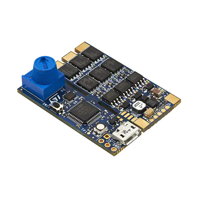
Electronic speed controller Discovery kit for drones with STM32G431CB Introduction The B-G431B-ESC1 Discovery kit is mainly based on the STM32G431CB microcontroller, the L6387 driver, and STL180N6F7 power MOSFETs. Its breakable form includes an electronic speed controller (ESC) board and a daughterboard for user interface with embedded ST-LINK/V2-1. The ESC has a very compacted size with the goal to drive a single 3-phase brushless motor (BLDC/PMSM), performing a sensorless field-oriented control (FOC) or 6-step control with speed regulation and active braking function. This unit can be connected with an external battery (LiPo type) and accepts a command signal from an external unit, for instance, a flight control board or similar. The system provides different communication buses (UART, CAN, PWM) for driving and monitoring, and also embeds an overcurrent and thermal protection circuit. The daughterboard contains an ST-LINK in-circuit debugger and programmer, allowing the user to program and debug the STM32G431CB microcontroller directly with a USB cable using a compatible toolset. Its form factor is suitable for small and very light R/C vehicles and their motor current capability, and also fits big vehicle requirements, for instance, a prosumer drone. . Figure 1. B-G431B-ESC1 Discovery kit (front view) Figure 2. B-G431B-ESC1 Discovery kit (bottom view) Pictures are not contractual. March 2021 UM2516 Rev 4 1/29 www.st.com 1 Contents UM2516 Contents 1 Features . . . . . . . . . . . . . . . . . . . . . . . . . . . . . . . . . . . . . . . . . . . . . . . . . . . 6 2 Ordering information . . . . . . . . . . . . . . . . . . . . . . . . . . . . . . . . . . . . . . . . 7 2.1 3 Codification . . . . . . . . . . . . . . . . . . . . . . . . . . . . . . . . . . . . . . . . . . . . . . . . . 7 Development environment . . . . . . . . . . . . . . . . . . . . . . . . . . . . . . . . . . . . 8 3.1 System requirements . . . . . . . . . . . . . . . . . . . . . . . . . . . . . . . . . . . . . . . . . 8 3.2 Development toolchains . . . . . . . . . . . . . . . . . . . . . . . . . . . . . . . . . . . . . . . 8 3.3 Software tool . . . . . . . . . . . . . . . . . . . . . . . . . . . . . . . . . . . . . . . . . . . . . . . 8 4 Description . . . . . . . . . . . . . . . . . . . . . . . . . . . . . . . . . . . . . . . . . . . . . . . . . 9 5 Hardware layout and configuration . . . . . . . . . . . . . . . . . . . . . . . . . . . . 11 6 7 5.1 Block diagram . . . . . . . . . . . . . . . . . . . . . . . . . . . . . . . . . . . . . . . . . . . . . . .11 5.2 Board dimensions . . . . . . . . . . . . . . . . . . . . . . . . . . . . . . . . . . . . . . . . . . . 13 5.3 Communication, programming, and command interfaces . . . . . . . . . . . . 14 5.4 Motor sensor connection (Hall or encoder) . . . . . . . . . . . . . . . . . . . . . . . 15 5.5 CAN connection and configuration . . . . . . . . . . . . . . . . . . . . . . . . . . . . . . 15 5.6 STM32G431CB pinout for motor control . . . . . . . . . . . . . . . . . . . . . . . . . 16 Connection and first execution of the electronic speed controller (ESC) program . . . . . . . . . . . . . . . . . . . . . . . . . . . . . . . . . . . . . . . . . . . . . . . . . . 19 6.1 First case: daughterboard not removed . . . . . . . . . . . . . . . . . . . . . . . . . . 19 6.2 Second case: daughterboard removed . . . . . . . . . . . . . . . . . . . . . . . . . . 21 B-G431B-ESC1 Discovery kit information . . . . . . . . . . . . . . . . . . . . . . 23 7.1 Product marking . . . . . . . . . . . . . . . . . . . . . . . . . . . . . . . . . . . . . . . . . . . . 23 7.2 B-G431B-ESC1 product history . . . . . . . . . . . . . . . . . . . . . . . . . . . . . . . . 24 7.3 2/29 7.2.1 Product identification BG431BESC1$AU1 . . . . . . . . . . . . . . . . . . . . . . 24 7.2.2 Product identification BG431BESC1$AU2 . . . . . . . . . . . . . . . . . . . . . . 24 7.2.3 Product identification BG431BESC1$AU3 . . . . . . . . . . . . . . . . . . . . . . 24 Board revision history . . . . . . . . . . . . . . . . . . . . . . . . . . . . . . . . . . . . . . . . 25 UM2516 Rev 4 UM2516 Contents Appendix A Federal Communications Commission (FCC) and ISED Canada Compliance Statements. . . . . . . . . . . . . . . . . . . . . . . 26 A.1 FCC Compliance Statement . . . . . . . . . . . . . . . . . . . . . . . . . . . . . . . . . . . 26 A.2 ISED Compliance Statement. . . . . . . . . . . . . . . . . . . . . . . . . . . . . . . . . . . 27 Revision history . . . . . . . . . . . . . . . . . . . . . . . . . . . . . . . . . . . . . . . . . . . . . . . . . . . . 28 UM2516 Rev 4 3/29 3 List of tables UM2516 List of tables Table 1. Table 2. Table 3. Table 4. Table 5. Table 6. Table 7. 4/29 Ordering information . . . . . . . . . . . . . . . . . . . . . . . . . . . . . . . . . . . . . . . . . . . . . . . . . . . . . . . 7 Codification explanation . . . . . . . . . . . . . . . . . . . . . . . . . . . . . . . . . . . . . . . . . . . . . . . . . . . . 7 Truth table. . . . . . . . . . . . . . . . . . . . . . . . . . . . . . . . . . . . . . . . . . . . . . . . . . . . . . . . . . . . . . 16 Main board STM32G431CB pinout for motor control . . . . . . . . . . . . . . . . . . . . . . . . . . . . . 16 Input/output terminal table . . . . . . . . . . . . . . . . . . . . . . . . . . . . . . . . . . . . . . . . . . . . . . . . . 18 SWD connector for MCU programming (daughterboard removed) . . . . . . . . . . . . . . . . . . 21 Document revision history . . . . . . . . . . . . . . . . . . . . . . . . . . . . . . . . . . . . . . . . . . . . . . . . . 28 UM2516 Rev 4 UM2516 List of figures List of figures Figure 1. Figure 2. Figure 3. Figure 4. Figure 5. Figure 6. Figure 7. Figure 8. Figure 9. Figure 10. Figure 11. Figure 12. Figure 13. Figure 14. Figure 15. Figure 16. B-G431B-ESC1 Discovery kit (front view) . . . . . . . . . . . . . . . . . . . . . . . . . . . . . . . . . . . . . . 1 B-G431B-ESC1 Discovery kit (bottom view). . . . . . . . . . . . . . . . . . . . . . . . . . . . . . . . . . . . . 1 Target application . . . . . . . . . . . . . . . . . . . . . . . . . . . . . . . . . . . . . . . . . . . . . . . . . . . . . . . . . 6 System structure overview . . . . . . . . . . . . . . . . . . . . . . . . . . . . . . . . . . . . . . . . . . . . . . . . . 10 Block diagram with ST products . . . . . . . . . . . . . . . . . . . . . . . . . . . . . . . . . . . . . . . . . . . . . 11 B-G431B-ESC1 top view . . . . . . . . . . . . . . . . . . . . . . . . . . . . . . . . . . . . . . . . . . . . . . . . . . 11 B-G431B-ESC1 bottom view . . . . . . . . . . . . . . . . . . . . . . . . . . . . . . . . . . . . . . . . . . . . . . . 12 B-G431B-ESC1 board mechanical dimensions (top view) . . . . . . . . . . . . . . . . . . . . . . . . . 13 Communication, programming, and command interfaces . . . . . . . . . . . . . . . . . . . . . . . . . 14 Motor sensor connection . . . . . . . . . . . . . . . . . . . . . . . . . . . . . . . . . . . . . . . . . . . . . . . . . . 15 ESC connections with CAN communication . . . . . . . . . . . . . . . . . . . . . . . . . . . . . . . . . . . . 16 B-G431B-ESC1 connection for MCU programming . . . . . . . . . . . . . . . . . . . . . . . . . . . . . . 19 ST MC Workbench screen . . . . . . . . . . . . . . . . . . . . . . . . . . . . . . . . . . . . . . . . . . . . . . . . . 20 B-G431B-ESC1 I/O connection . . . . . . . . . . . . . . . . . . . . . . . . . . . . . . . . . . . . . . . . . . . . . 20 PWM input signal for motor speed regulation . . . . . . . . . . . . . . . . . . . . . . . . . . . . . . . . . . . 21 SWD configuration on IAR tool . . . . . . . . . . . . . . . . . . . . . . . . . . . . . . . . . . . . . . . . . . . . . . 22 UM2516 Rev 4 5/29 5 Features 1 UM2516 Features • Full reference design for electronic speed controller capable of both sensorless FOC and 6-step algorithm • Designed for drones with up to 6S LiPo battery pack or equivalent suitable DC supply • 3-phase driver board for BLDC/PMSM motors with discrete N-channel 60 V, 120 A STripFET F7 power MOSFETs • Arm®(a) Cortex®-M4 32-bit STM32G431CB MCU, 213 DMIPS, 128 Kbytes of Flash memory, 32 Kbytes of SRAM, analog rich, math accelerator • On-board ST-LINK/V2-1 debugger /programmer detachable from the main board • Output peak motor current (maximum peak current tested with a propeller to have an air-forced cooling): 40 A • Designed with SMD ceramic capacitors with very low profiles • BEC available through the daughterboard (5 V for external board supplying, for example a flight control board) • Support for motor sensors (Hall or encoder) • Supported by ST motor control software development kit (SDK) with ST motor profiler • 3-shunt mode supported for motor current sensing • L6387 High voltage high and low-side driver with integrated interlocking function • Overcurrent and overvoltage protection feature (OCP/OVP) • Thermal measuring and overheating protection with NTC on board • ESC ready for communication with any standard flight control unit (FCU): PWM/CAN/UART • Potentiometer and user button available on the daughterboard • 2 user LEDs: 1 green LED for 3.3 V level, and 1 red LED configurable by the user • Target applications: motor driving for R/C vehicles, UAV drone, electric car, or boat • PCB type and size: • – FR-4 PCB material – 8-layer layout – Dimensions (including the daughterboard with ST-LINK part): 30 mm x 41 mm – Weight (including the daughterboard with ST-LINK part): 9.2 g RoHS compliant Figure 3. Target application a. Arm is a registered trademark of Arm Limited (or its subsidiaries) in the US and/or elsewhere. 6/29 UM2516 Rev 4 UM2516 2 Ordering information Ordering information To order the B-G431B-ESC1 Discovery kit, refer to Table 1. Additional information is available from the datasheet and reference manual of the target STM32. Table 1. Ordering information 2.1 Order code Board reference Target STM32 B-G431B-ESC1 MB1419 STM32G431CBU6 Codification The meaning of the codification of the Discovery kit is explained in Table 2. Table 2. Codification explanation B-XXYYZ-ESCN Description Example: B-G431B-ESC1 XX MCU series in STM32 32-bit Arm Cortex MCUs STM32G4 Series YY MCU product line in the series STM32G431 Z STM32 Flash memory size: – B for 128 Kbytes 128 Kbytes ESCN Electronic speed controller version number ESC1 UM2516 Rev 4 7/29 28 Development environment UM2516 3 Development environment 3.1 System requirements 3.2 3.3 • Windows® OS (7, 8 and 10), Linux® 64-bit, or macOS®(a)(b) • USB Type-A or USB Type-C® to Micro-B cable Development toolchains • IAR Systems® - IAR Embedded Workbench®(c) • Keil® - MDK-ARM(c) • STMicroelectronics - STM32CubeIDE Software tool This board is supported by the X-CUBE-MCSDK STM32Cube Expansion Package dedicated for motor-control applications. The source code is available and it is included and generated with this tool. The B-G431B-ESC1 does not have a demonstration firmware preloaded in the STM32 Flash memory, so for the first usage, the user must connect it with the X-CUBE-MCSDK tool. a. macOS® is a trademark of Apple Inc. registered in the U.S. and other countries. b. All other trademarks are the property of their respective owners. c. 8/29 On Windows® only. UM2516 Rev 4 UM2516 4 Description Description The B-G431B-ESC1 Discovery kit is an electronic speed controller (ESC) that drives a single 3-phase brushless motor with very high-performance control. It is commonly used inside the R/C field, for instance, drones, electric cars, and boats, to provide fast and efficient propulsion for the movement. This unit must be capable of low- and very highspeed regulation and strong dynamic response to different load conditions. An external signal, through a communication bus between the ESC board and a generic central unit, sets the reference value for the speed regulation, and another signal sends the status of the system. For instance, if a fault occurs, a central unit can decide to enable an emergency procedure. In the mass market, a lot of ESCs are available to cover different kinds of R/C models, from the toy up to the professional unit, with different motor current capabilities, different sizes, and input voltage requirements. All of these boards are based on the same control algorithm, 6-step or trapezoidal, with no shunt resistors in a lot of cases. B-G431B-ESC1 performs otherwise more sophisticated and smart control algorithm based on Field Oriented Control (FOC) comparing with the 6-step algorithm, in particular, it offers the following features: • Better torque control • Motor current regulation in case of a fast load change • Vibration reduction • Active braking function • Better efficiency • Noise reduction • A real-time monitor of the rotor speed • Energy recovery during the deceleration The Discovery kit is also compatible with the 6-step control with embedded Bemf hardware circuit for rotor position estimation. UM2516 Rev 4 9/29 28 Description UM2516 The typical system architecture is shown in Figure 4. Each ESC board is connected with a single brushless motor, in this case, a quadcopter system is taken as an example. An external LiPo battery provides the right power to the four connected boards and through a wired bus, each ESC board receives or sends commands from or to an external unit, for instance, a flight control unit. Figure 4. System structure overview The B-G431B-ESC1 provides the maximum flexibility in term of communication protocol (UART, PWM, and CAN are available on-board), and it also contains a DC-DC converter on the daughterboard, with 5 V output connector (BEC) to supply an external board, for instance, a flight control unit or sensors. 10/29 UM2516 Rev 4 UM2516 Hardware layout and configuration 5 Hardware layout and configuration 5.1 Block diagram The B-G431B-ESC1 Discovery kit is a complete hardware platform (power and control) based on several ST products as shown in the following block diagram: Figure 5. Block diagram with ST products The top side is mainly dedicated to the power section. It is composed of power MOSFETs, gate drivers, and a DC-DC converter. Figure 6. B-G431B-ESC1 top view UM2516 Rev 4 11/29 28 Hardware layout and configuration UM2516 The bottom side is mainly dedicated to the digital section. It is composed of the STM32G431CB microcontroller that performs a three shunt both sensorless and sensored FOC control and 6-step control in an LQFP 48pin package. The STM32G431CB devices are based on the high-performance Arm® Cortex®-M4 32-bit RISC core. They operate at a frequency of up to 170 MHz. The Cortex-M4 core features a single-precision floating-point unit (FPU), which supports all the Arm® single-precision dataprocessing instructions and all the data types. It also implements a full set of DSP (digital signal processing) instructions and a memory protection unit (MPU) which enhances the application's security. The devices embed peripherals allowing mathematical/arithmetic function acceleration (CORDIC co-processor for trigonometric functions and FMAC unit for Filter Functions). They offer two fast 12-bit ADCs (5 Msps), four comparators, three operational amplifiers, four DAC channels (2 external and 2 internal), an internal voltage reference buffer, a lowpower RTC, one general-purpose 32-bit timers, two 16-bit PWM timers dedicated to motor control, seven general-purpose 16-bit timers, and one 16-bit low-power timer. Figure 7. B-G431B-ESC1 bottom view 12/29 UM2516 Rev 4 UM2516 5.2 Hardware layout and configuration Board dimensions The total dimension of the B-G431B-ESC1 Discovery kit (PCB) is 30 mm x 41 mm as shown in Figure 8. Figure 8. B-G431B-ESC1 board mechanical dimensions (top view) UM2516 Rev 4 13/29 28 Hardware layout and configuration 5.3 UM2516 Communication, programming, and command interfaces The B-G431B-ESC1 Discovery kit is equipped with a USB connector and different pads for communication, such as: • U4 USB port for programming and debugging • J1 for CAN port • J2 for SWD-STM32F103 (reserved) • J3 for PWM/UART/BECout input/output signal • J4 for SWD-STM32G431 debug/programming port (without daughterboard) • J8 for motor sensor (Hall or encoder) Figure 9. Communication, programming, and command interfaces The USB interface is provided on the daughterboard and it allows to program and debug the main board. It provides also the supply voltage to the STM32G431CB MCU in case of no voltage on the bus (J5 and J6 not connected to the LiPo battery). The USB port is available to use the ST MC Workbench and Motor Profiler tool directly connected with the PC (no external dongle is needed). The CAN interface is provided with an onboard transceiver and a termination resistor is provided and manageable by firmware. The J1 connector has also 5V and GND pins (see Section 5.5 for further info) The J2 is reserved to program the MCU on the daughterboard. The J3 pads are available on the top side of the main board. They provide the UART TX and RX (for telemetry and firmware update respectively), the input PWM channel for motor speed regulation. In particular, the PWM input signal (5 V tolerant) sets the motor speed according to the Ton duration, for instance, 1060 µs for the minimal speed and 1860 µs for the maximum speed. Other pins are for GND and 5 V. It is a power line to supply an external board, for example, a flight control unit or equivalent. This voltage line is available only if the daughterboard is not removed. 14/29 UM2516 Rev 4 UM2516 Hardware layout and configuration The J4 solder pads provide the SWD connection between the STM32G431CB and the external ST-LINK programmer if the daughterboard is removed. In this case, other pins are available, such as 3V3 and GND. The J8 solder pads allow the connection of the motor sensor, Hall, or encoder. Refer to Section 5.4 for further information. 5.4 Motor sensor connection (Hall or encoder) The Discovery kit embeds the hardware circuit for Hall or encoder sensor. A supply voltage line is provided with 5 V and GND lines in J8 solder pads. This voltage is available also if the daughterboard is removed. The ST MC workbench must be configured to use these sensors during the FOC control. Figure 10. Motor sensor connection 5.5 CAN connection and configuration The main board includes the transceiver and the connection pads to use the CAN peripheral available in the STM32G431CB MCU. The hardware circuit is based on UAVCAN standard (https://uavcan.org/) so a little fuse is included to protect by overcurrent so that an accidental short circuit on the device does not bring down the power on the entire bus. One CAN output (J1) is provided on-board and T-connectors are needed to create the bus line with several boards. This circuit accepts also the supply voltage from the external unit, for example, a flight control unit with a power CAN (5.0 V to 5.5 V on the bus power line). In this case, J1 solder pads contain the 5V line (input) and if a voltage is applied to it, the main board generates the 3.3 V for G4MCU and the transceiver. This feature allows keeping the communication also when the battery is discharged or removed. Figure 11 shows that two terminator resistors are needed to open and close the CAN bus line. B-G431B-ESC1 includes this terminator resistor (120 Ω) and it is manageable by firmware (CAN_TERM pin) with a low voltage single-pole-double-throw analog onboard switch (see the CAN page on the electrical schematic). Table 3 shows the logic to add or remove this resistor. UM2516 Rev 4 15/29 28 Hardware layout and configuration UM2516 Figure 11. ESC connections with CAN communication Table 3. Truth table CAN_TERM pin 120 Ω resistor H ON L OFF(1) 1. High impedance 5.6 STM32G431CB pinout for motor control Table 4. Main board STM32G431CB pinout for motor control Pin 16/29 Default Signal Solder Bridge 1 VBAT 3V3 - 2 PC13/TAMP/RTC TIM1_CH1N - 3 PC14 CAN_TERM R26 4 PC15 N.C. - 5 PF0/OSC-IN OSC 8Mhz - 6 PF1/OSC-OUT OSC 8Mhz R27 7 PG10/NRST RESET - 8 PA0 VBUS - 9 PA1 Curr_fdbk1_OPAmp+ - 10 PA2 OP1_OUT - 11 PA3 Curr_fdbk1_OPAmp- - 12 PA4 BEMF1 - 13 PA5 Curr_fdbk2_OPAmp- - 14 PA6 OP2_OUT - UM2516 Rev 4 UM2516 Hardware layout and configuration Table 4. Main board STM32G431CB pinout for motor control (continued) Pin Default Signal Solder Bridge 15 PA7 Curr_fdbk2_OPAmp+ - 16 PC4 BEMF2 - 17 PB0 Curr_fdbk3_OPAmp+ - 18 PB1 TP3 - 19 PB2 Curr_fdbk3_OPAmp- - 20 VREF+ 3v3 - 21 VDDA 3v3 - 22 PB10 N.C. - 23 VDD4 3V3 - 24 PB11 BEMF3 - 25 PB12 POTENTIOMETER - 26 PB13 N.C. - 27 PB14 Temperature feedback - 28 PB15 TIM1_CH3N - 29 PC6 STATUS - 30 PA8 TIM1_CH1 - 31 PA9 TIM1_CH2 - 32 PA10 TIM1_CH3 - 33 PA11 CAN_RX - 34 PA12 TIM1_CH2N - 35 VDD6 3V3 - 36 PA13 SWDIO - 37 PA14 SWCLK - 38 PA15 PWM - 39 PC10 BUTTON - 40 PC11 CAN_SHDN,TP2 - 41 PB3 USART2_TX - 42 PB4 USART2_RX - 43 PB5 GPIO_BEMF - 44 PB6 A+/H1 - 45 PB7 B+/H2 - 46 PB8 Z+/H3 - 47 PB9 CAN_TX - 48 VDD8 3V3 - UM2516 Rev 4 17/29 28 Hardware layout and configuration UM2516 Table 5. Input/output terminal table Main I/O Terminal 18/29 Function J5/J6 LiPo battery power input (3S-6S) J7 3-phase motor connector UM2516 Rev 4 UM2516 6 Connection and first execution of the electronic speed controller (ESC) program Connection and first execution of the electronic speed controller (ESC) program For the correct usage and the first run of the B-G431B-ESC1 Discovery kit, the procedure explained in Section 6.1 or Section 6.2 is suggested. The ESC board is usually powered with a battery (on J5 and J6 input connectors). It can be supplied with a laboratory power supply during software development. In this case, it is recommended to disconnect the power supply wires when the supply is switched-off while USB is connected (Some power supply types may cause board overheating in this case). 6.1 First case: daughterboard not removed 1. Connect a micro USB cable to the USB port on the daughterboard as shown in Figure 12, and verify if the green led (D5) is turned on in the main board. Figure 12. B-G431B-ESC1 connection for MCU programming 2. Connect the other part of the cable to the PC port and run the ST MC Workbench tool for motor and parameter configuration (see Figure 13). 3. Generate and upload the firmware code into the STM32G431CB MCU with the available IDE tool. UM2516 Rev 4 19/29 28 Connection and first execution of the electronic speed controller (ESC) program UM2516 Figure 13. ST MC Workbench screen 4. Solder the three motor wires U, V, W at the motor (J7) solder pad with no particular color sequence (see Figure 14) 5. Solder the PWM input and GND at J3 connector (pin 4 and pin 5). The PWM input signal is either 3.3 V or 5 V (the PWM is connected to a 5 V tolerant MCU input pin). 6. Connect the main board with a LiPo battery (or DC power supply: min 3S - max 6S) with the right polarity and turn ON. The input connector is composed of two large pads for soldering. The Transil device prevents damage in case of reverse polarity at the input side for a low time. Figure 14. B-G431B-ESC1 I/O connection 20/29 UM2516 Rev 4 UM2516 Connection and first execution of the electronic speed controller (ESC) program 7. Generate on J3 connector a PWM signal at 490 Hz and duty cycle value between 1060 µs and 1860 µs, the motor starts to rotate respectively from the minimum to the maximum speed. The ESC is not armed (no driving signals generated) if the duty cycle is lower than 1060 µs. Figure 15. PWM input signal for motor speed regulation Note: In case the motor is already started, a blank time of 1500 ms on the PWM signal determines the switch off of the system (ESC turned OFF). 6.2 Second case: daughterboard removed In case the daughterboard is removed, Table 6 shows the relation between the SWD pinout on the main board and SWD on ST-LINK/V2 (not isolated version) external programmer. Table 6. SWD connector for MCU programming (daughterboard removed) Pin no. in STLINK STLINK/V2 connector ST-LINK/V2 function Target connection (SWD) Pin no. in DK B-G431BESC1 (J4 pad) 1 VAPP Target VCC MCU VDD 3 2 VAPP Target VCC MCU VDD 3 6 GND - GND 4 7 - SW IO SWDIO 1 9 - SW CLK SWCLK 2 Set the SWD interface inside the IDE tool, for instance, a picture of IAR Workbench is shown in Figure 16. If the daughterboard is removed the following pad connections are available on it: • On the top side -> SWDIO, SWCLK • On the bottom side -> NRST, +10V,+5V, 5V_ESC, GND UM2516 Rev 4 21/29 28 Connection and first execution of the electronic speed controller (ESC) program Figure 16. SWD configuration on IAR tool 22/29 UM2516 Rev 4 UM2516 UM2516 B-G431B-ESC1 Discovery kit information 7 B-G431B-ESC1 Discovery kit information 7.1 Product marking The stickers located on the top or bottom side of the PCB provide product information: • Product order code and product identification for the first sticker • Board reference with revision, and serial number for the second sticker On the first sticker, the first line provides the product order code, and the second line the product identification. On the second sticker, the first line has the following format: “MBxxxx-Variant-yzz”, where “MBxxxx” is the board reference, “Variant” (optional) identifies the mounting variant when several exist, "y" is the PCB revision and "zz" is the assembly revision, for example B01. The second line shows the board serial number used for traceability. Evaluation tools marked as “ES” or “E” are not yet qualified and therefore not ready to be used as reference design or in production. Any consequences deriving from such usage will not be at ST charge. In no event, ST will be liable for any customer usage of these engineering sample tools as reference designs or in production. “E” or “ES” marking examples of location: • On the targeted STM32 that is soldered on the board (For an illustration of STM32 marking, refer to the STM32 datasheet “Package information” paragraph at the www.st.com website). • Next to the evaluation tool ordering part number that is stuck or silk-screen printed on the board. UM2516 Rev 4 23/29 28 B-G431B-ESC1 Discovery kit information UM2516 7.2 B-G431B-ESC1 product history 7.2.1 Product identification BG431BESC1$AU1 This product identification is based on the mother board MB1419-G431CBU6-B01. It embeds the STM32G431CBU6 microcontroller with silicon revision code "Z". The limitations of this silicon revision are detailed in the errata sheet STM32G431xx/441xx device errata (ES0431). 7.2.2 Product identification BG431BESC1$AU2 This product identification is based on the mother board MB1419-G431CBU6-B04. It embeds the STM32G431CBU6 microcontroller with silicon revision code "Y". The limitations of this silicon revision are detailed in the errata sheet STM32G431xx/441xx device errata (ES0431). 7.2.3 Product identification BG431BESC1$AU3 This product identification is based on the mother board MB1419-G431CBU6-C01. It embeds the STM32G431CBU6 microcontroller with silicon revision code "X". The limitations of this silicon revision are detailed in the errata sheet STM32G431xx/441xx device errata (ES0431). 24/29 UM2516 Rev 4 UM2516 7.3 B-G431B-ESC1 Discovery kit information Board revision history Revision B-01 The revision B-01 of the MB1419 board is the initially released version. Limitations Over lighting of the LD2 LED Revision B-04 The revision B-04 of the MB1419 board removes the limitations of the revision B01 by setting the resistor value of R8 and R9 to 470 Ω. Limitations No limitation is identified for this board. Revision C-01 The revision C-01 of the MB1419 board replaces some part references and improves the PCB layout. Limitations No limitation is identified for this board. UM2516 Rev 4 25/29 28 Federal Communications Commission (FCC) and ISED Canada Compliance Statements UM2516 Appendix A A.1 Federal Communications Commission (FCC) and ISED Canada Compliance Statements FCC Compliance Statement Identification of product: ST / B-G431B-ESC1 Part 15.19 This device complies with Part 15 of the FCC Rules. Operation is subject to the following two conditions: (1) this device may not cause harmful interference, and (2) this device must accept any interference received, including interference that may cause undesired operation. Part 15.21 Any changes or modifications to this equipment not expressly approved by STMicroelectronics may cause harmful interference and void the user’s authority to operate this equipment. Part 15.105 This equipment has been tested and found to comply with the limits for a Class B digital device, pursuant to part 15 of the FCC Rules. These limits are designed to provide reasonable protection against harmful interference in a residential installation. This equipment generates uses and can radiate radio frequency energy and, if not installed and used in accordance with the instructions, may cause harmful interference to radio communications. However, there is no guarantee that interference will not occur in a particular installation. If this equipment does cause harmful interference to radio or television reception, which can be determined by turning the equipment off and on, the user is encouraged to try to correct the interference by one or more of the following measures: Note: • Reorient or relocate the receiving antenna. • Increase the separation between the equipment and the receiver. • Connect the equipment into an outlet on a circuit different from that to which the receiver is connected. • Consult the dealer or an experienced radio/TV technician for help. Use only shielded cables. Responsible party (in the USA) Terry Blanchard Americas Region Legal | Group Vice President and Regional Legal Counsel, The Americas STMicroelectronics, Inc. 750 Canyon Drive | Suite 300 | Coppell, Texas 75019 USA Telephone: +1 972-466-7845 26/29 UM2516 Rev 4 UM2516 Federal Communications Commission (FCC) and ISED Canada Compliance Statements A.2 ISED Compliance Statement This device complies with FCC and ISED Canada RF radiation exposure limits set forth for general population for mobile application (uncontrolled exposure). This device must not be collocated or operating in conjunction with any other antenna or transmitter. Compliance Statement Notice: This device complies with ISED Canada licence-exempt RSS standard(s). Operation is subject to the following two conditions: (1) this device may not cause interference, and (2) this device must accept any interference, including interference that may cause undesired operation of the device. ISED Canada ICES-003 Compliance Label: CAN ICES-3 (B) / NMB-3 (B). Déclaration de conformité Avis: Le présent appareil est conforme aux CNR d'ISDE Canada applicables aux appareils radio exempts de licence. L'exploitation est autorisée aux deux conditions suivantes : (1) l'appareil ne doit pas produire de brouillage, et (2) l'utilisateur de l'appareil doit accepter tout brouillage radioélectrique subi, même si le brouillage est susceptible d'en compromettre le fonctionnement. Étiquette de conformité à la NMB-003 d'ISDE Canada : CAN ICES-3 (B) / NMB-3 (B). UM2516 Rev 4 27/29 28 Revision history UM2516 Revision history Table 7. Document revision history Date Revision 8-Apr-2019 1 Initial release. 17-Jan-2020 2 Added: – Section 3.3: Software tool – Recommendation note in Section 6 introduction 3 Added: – Section 7: B-G431B-ESC1 Discovery kit information with updated Product marking, B-G431B-ESC1 product history, and Board revision history – Class-B Section Appendix A: Federal Communications Commission (FCC) and ISED Canada Compliance Statements Removed: – Schematic diagrams 4 Updated: – Third mother board identification in Section 7.2.3: Product identification BG431BESC1$AU3 – Third board revision in Section 7.3: Board revision history 18-Feb-2021 23-Mar-2021 28/29 Changes UM2516 Rev 4 UM2516 IMPORTANT NOTICE – PLEASE READ CAREFULLY STMicroelectronics NV and its subsidiaries (“ST”) reserve the right to make changes, corrections, enhancements, modifications, and improvements to ST products and/or to this document at any time without notice. Purchasers should obtain the latest relevant information on ST products before placing orders. ST products are sold pursuant to ST’s terms and conditions of sale in place at the time of order acknowledgement. Purchasers are solely responsible for the choice, selection, and use of ST products and ST assumes no liability for application assistance or the design of Purchasers’ products. No license, express or implied, to any intellectual property right is granted by ST herein. Resale of ST products with provisions different from the information set forth herein shall void any warranty granted by ST for such product. ST and the ST logo are trademarks of ST. For additional information about ST trademarks, please refer to www.st.com/trademarks. All other product or service names are the property of their respective owners. Information in this document supersedes and replaces information previously supplied in any prior versions of this document. © 2021 STMicroelectronics – All rights reserved UM2516 Rev 4 29/29 29
B-G431B-ESC1 价格&库存

很抱歉,暂时无法提供与“B-G431B-ESC1”相匹配的价格&库存,您可以联系我们找货

免费人工找货