BUL1102E
High voltage fast-switching
NPN power transistor
Features
■
High voltage capability
■
Very high switching speed
TAB
Applications
Four lamp electronic ballast for:
3
3
■
120 V mains in push-pull configuration
■
277 V mains in half bridge current feed
configuration
1
2
2
1
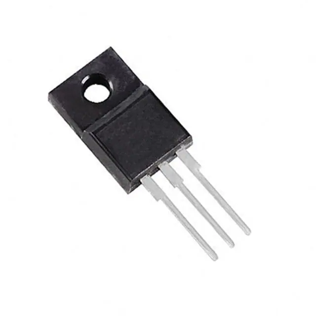
TO-220FP
TO-220
Description
This is a high voltage fast switching NPN power
transistor manufactured in multi epitaxial planar
technology. It uses a cellular emitter structure with
planar edge termination to enhance switching
speeds while maintaining a wide RBSOA.
Figure 1.
Thanks to an increased intermediate layer, it has
an intrinsic ruggedness which enables the
transistor to withstand a high collector current
level during breakdown condition, without using
the Transil™ protection usually necessary in
typical converters for lamp ballast.
Table 1.
Internal schematic diagram
C
(2, TAB)
E
(3)
(1)
B
Device summary
Order codes
Marking
Package
Packaging
BUL1102E
BUL1102E
TO-220
Tube
BUL1102EFP
BUL1102EFP
TO-220FP
Tube
February 2012
Doc ID 7929 Rev 5
1/13
www.st.com
13
�Absolute maximum ratings
1
Absolute maximum ratings
Table 2.
Absolute maximum ratings
Symbol
Parameter
Value
Unit
VCES
Collector-emitter voltage (VBE = 0)
1100
V
VCEO
Collector-emitter voltage (IB = 0)
450
V
VEBO
Emitter-base voltage (IC = 0)
12
V
Collector current
4
A
Collector peak current (tP < 5 ms)
8
A
Base current
2
A
Base peak current (tP < 5 ms)
4
A
PTOT
BUL1102E total dissipation at TC = 25°C
BUL1102EFP total dissipation at TC = 25 °C
70
30
W
VISO
BUL1102EFP insolation withstand voltage (RMS) from
all three leads to external heatsink
1500
V
TSTG
Storage temperature
-65 to 150
°C
150
°C
Value
Unit
BUL1203E thermal resistance junction-case
1.8
°C/W
BUL1203EFP thermal resistance junction-case
4.2
°C/W
IC
ICM
IB
IBM
TJ
Table 3.
Symbol
RthJC
2/13
BUL1102E
Max. operating junction temperature
Thermal data
Parameter
Doc ID 7929 Rev 5
�BUL1102E
2
Electrical characteristics
Electrical characteristics
(TJ = 25 °C; unless otherwise specified)
Table 4.
Symbol
Electrical characteristics
Parameter
Test conditions
ICES
Collector cut-off
current (VBE = 0)
VCE =1100 V
IEBO
Emitter cut-off current
(IC = 0)
VEB = 12 V
Collector-emitter
VCEO(sus)(1) sustaining voltage
(IB=0)
IC = 100 mA
Collector-emitter
saturation voltage
IC = 2 A
VBE(sat)(1)
Base-emitter
saturation voltage
IC = 2 A
DC current gain
IC = 250 mA_ VCE = 5 V
VCE = 5 V
IC = 2 A,
for BUL1102E
VCE = 5 V
IC = 2 A_
for BUL1102EFP
hFE(1)
ts
tf
Ear
100
µA
1
mA
450
VCE(sat)(1)
_
Min. Typ. Max. Unit
V
IB =400 mA
1.5
V
IB = 400 mA
1.5
V
Resistive load
Storage time
Fall time
IC = 2.5 A
VCC = 250 V
IB1 = 0.5 A
IB2 = 1 A
TP=30 µs (see Figure 14)
Avalanche energy
L = 2 mH
C = 1.8 nF
IBR ≤ 2.5 A
25 °C < TC
很抱歉,暂时无法提供与“BUL1102EFP”相匹配的价格&库存,您可以联系我们找货
免费人工找货- 国内价格 香港价格
- 1+20.120941+2.60219
- 50+9.7038850+1.25498
- 100+8.69336100+1.12429
- 500+6.91929500+0.89486
- 1000+6.348741000+0.82107
- 2000+5.868902000+0.75901
- 5000+5.349915000+0.69189
- 10000+5.0656210000+0.65513
- 国内价格
- 1+17.10458
- 10+9.11526
- 50+7.90548
- 100+7.62999
- 500+7.16284
- 国内价格
- 50+7.60835
- 250+7.45631