BZW50
Datasheet
5 kW TVS
Features
•
R6
•
•
•
•
•
Peak pulse power:
–
5000 W (10/1000 µs)
Stand off voltage range from 10 V to 180 V
Unidirectional and bidirectional diode
Low clamping factor
Fast response time
UL497B, file number: QVGQ2.E136224
Description
Transil diodes provide high overvoltage protection by clamping action. Their
instantaneous response to transient overvoltages makes them particularly suited to
protect voltage sensitive devices such as MOS Technology and low voltage supplied
ICs.
Product status link
BZW50
DS0662 - Rev 6 - June 2018
For further information contact your local STMicroelectronics sales office.
www.st.com
�BZW50
Characteristics
1
Characteristics
Table 1. Absolute maximum ratings (Tamb = 25 °C)
Symbol
Value
Unit
5000
W
Power dissipation on infinite heatsink
6.5
W
IFSM
Non repetitive surge peak forward current for unidirectional types
500
A
Tstg
Storage temperature range
-65 to +175
°C
Top
Maximum operating junction temperature
175
°C
TL
Maximum lead temperature for soldering during 10 s at 5 mm from case.
260
°C
PPP
P
Parameter
Peak pulse power dissipation(1)
1. For a surge greater than the maximum values, the diode will fail in short-circuit.
Table 2. Thermal resistance parameter
Symbol
Parameter
Value
Unit
Rth(j-l)
Junction to leads
15
°C/W
Rth(j-a)
Junction to ambient on printed circuit. L lead = 10 mm
65
°C/W
Figure 1. Electrical characteristics (definitions)
Symbol
VRM
VBR
VCL
IRM
IPP
αT
VF
RD
Parameter
Stand-off voltage
Breakdown voltage
Clamping voltage
Leakage current @ VRM
Peak pulse current
Voltage temperature coefficient
Forward voltage drop
Dynamic resistance
Unidirectional
I
I
IF
IPP
VF
VCL VBR VRM
V
VCLVBR VRM
IRM
IR
IPP
IR
IRM
V
IRM
IR
IPP
VRMVBR VCL
Bidirectional
Figure 2. Pulse definition for electrical characteristics
DS0662 - Rev 6
page 2/10
�BZW50
Characteristics
Table 3. Electrical characteristics - values (Tamb = 25 °C)
Order code
Unidirectional Bidirectional
IRM @ VRM
max.
VBR @ IR(1) min.
VCL @ IPP
10/1000 µs max.
VCL @ IPP 8/20 µs
max.
αT(2)
C(3)typ.
µA
V
V
mA
V
A
V
A
10-4/°C
pF
BZW50-10
BZW50-10B
5
10
11.1
1
18.8
266
23.4
2564
7.8
24000
BZW50-12
BZW50-12B
5
12
13.3
1
22
227
28
2143
8.4
18500
BZW50-15
BZW50-15B
5
15
16.6
1
26.9
186
35
1714
8.8
13500
BZW50-18
BZW50-18B
5
18
20
1
32.2
155
41.5
1446
9.2
11500
BZW50-22
BZW50-22B
5
22
24.4
1
39.4
127
51
1177
9.6
8500
BZW50-27
BZW50-27B
5
27
30
1
48.3
103
62
968
9.8
7000
BZW50-33
BZW50-33B
5
33
36.6
1
59
85
76
789
10
5750
BZW50-39
BZW50-39B
5
39
43.3
1
69.4
72
90
667
10.1
4800
BZW50-47
BZW50-47B
5
47
52
1
83.2
60.1
108
556
10.3
4100
BZW50-56
BZW50-56B
5
56
62.2
1
99.6
50
129
465
10.4
3400
BZW50-68
BZW50-68B
5
68
75.6
1
121
41
157
382
10.5
3000
BZW50-82
BZW50-82B
5
82
91
1
145
34
189
317
10.6
2600
BZW50-100
BZW50-100B
5
100
111
1
179
28
228
263
10.7
2300
BZW50-120
BZW50-120B
5
120
133
1
215
23
274
219
10.8
1900
BZW50-150
BZW50-150B
5
150
166
1
269
19
343
175
10.8
1700
BZW50-180
BZW50-180B
5
180
200
1
322
16
410
146
10.8
1500
1. Pulse test: tp < 50 ms.
2. To calculate VBR versus Tj: VBR at TJ = VBR at 25 °C x (1 + αT x (Tj - 25))
3. VR = 0 V, F = 1 MHz. For bidirectional types, capacitance value is divided by 2.
DS0662 - Rev 6
page 3/10
�BZW50
Characteristics (curves)
1.1
Characteristics (curves)
Figure 3. Peak power dissipation vs. initial junction
temperature (printed circuit board)
Figure 4. Peak pulse power versus exponential pulse
duration
%
P p p(W)
1E7
100
T j initial(°C)
1E6
80
1E5
60
1E4
40
1E3
20
j
0
0
20
40
60
80
100 120 140 160 180 200
Figure 5. Clamping voltage vs. peak pulse current
1000
tp(ms)EXPO.
T initial (°C)
1E2
0.001
%I pp
10
1.0
Tj = 25 °C
F = 1 MHz
50
0
BZ W5 0-180
10 0
tr
tp
B ZW 5
t
t 220 V.
Figure 9. Transient thermal impedance junction to
ambient vs. pulse duration
100
Figure 10. Relative variation of leakage current vs.
junction temperature
Zth (j-a) (°C/W)
5E+3
IR (Tj)
IR (Tj = 25 °C)
VR = VRM
1E+3
1E+2
10
1E+1
1E+0
tp (s)
1
0.01
DS0662 - Rev 6
Tj (25°C)
1E-1
0.1
1
10
100
1000
0
25
50
75
100
125
150
page 5/10
�BZW50
Package information
2
Package information
In order to meet environmental requirements, ST offers these devices in different grades of ECOPACK®
packages, depending on their level of environmental compliance. ECOPACK® specifications, grade definitions
and product status are available at: www.st.com. ECOPACK® is an ST trademark.
2.1
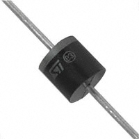
R6 package information
Figure 11. R6 package outline
B
B
A
ØD
ØC
Table 4. R6 package mechanical data
Dimensions
Millimeters
Ref.
DS0662 - Rev 6
Inches
Min.
Typ.
Max.
Typ.
Max.
A
8.6
-
9.1
0.338
-
0.358
B
25.4
-
1
-
C
8.6
-
9.1
0.338
-
0.358
D
1.20
-
1.30
0.047
-
0.051
page 6/10
�BZW50
R6 package information
Table 5. Marking
DS0662 - Rev 6
Unidirectional order code
Marking
Bidirectional order code
Marking
BZW50-10
BZW50-10
BZW50-10B
BZW50-10B
BZW50-12
BZW50-12
BZW50-12B
BZW50-12B
BZW50-15
BZW50-15
BZW50-15B
BZW50-15B
BZW50-18
BZW50-18
BZW50-18B
BZW50-18B
BZW50-22
BZW50-22
BZW50-22B
BZW50-22B
BZW50-27
BZW50-27
BZW50-27B
BZW50-27B
BZW50-33
BZW50-33
BZW50-33B
BZW50-33B
BZW50-39
BZW50-39
BZW50-39B
BZW50-39B
BZW50-47
BZW50-47
BZW50-47B
BZW50-47B
BZW50-56
BZW50-56
BZW50-56B
BZW50-56B
BZW50-68
BZW50-68
BZW50-68B
BZW50-68B
BZW50-82
BZW50-82
BZW50-82B
BZW50-82B
BZW50-100
BZW50-100
BZW50-100B
BZW50-100B
BZW50-120
BZW50-120
BZW50-120B
BZW50-120B
BZW50-150
BZW50-150
BZW50-150B
BZW50-150B
BZW50-180
BZW50-180
BZW50-180B
BZW50-180B
page 7/10
�BZW50
Ordering information
3
Ordering information
Figure 12. Ordering information scheme
BZW
50
10
CA
RL
Transil
Peak pulse power
50 = 5000 W
Breakdown voltage
100 = 100 V
Types
A = Unidirectional
CA = Bidirectional
Packaging
Blank = Ammopack tape
RL = Tape and reel
Table 6. Ordering information
Order code
Marking
Package
Weight
BZW50xxxx
BZW50xxxxB
BZW50xxxxRL
See Table 5. Marking
R6
BZW50xxxxBRL
Base qty.
Delivery mode
1000
Ammopack
100
Tape and reel
2.050 g
1. Logo, date code, type code, cathode band (for unidirectional types only).
DS0662 - Rev 6
page 8/10
�BZW50
Revision history
Table 7. Document revision history
DS0662 - Rev 6
Date
Revision
Changes
Feb-2003
1
Last update.
14-Dec-2012
2
Updated ECOPACK statement.
25-May-2018
3
Updated tittle description. Updated Figure 2. Pulse definition for electrical characteristics
and Figure 12. Ordering information scheme.
page 9/10
�BZW50
IMPORTANT NOTICE – PLEASE READ CAREFULLY
STMicroelectronics NV and its subsidiaries (“ST”) reserve the right to make changes, corrections, enhancements, modifications, and improvements to ST
products and/or to this document at any time without notice. Purchasers should obtain the latest relevant information on ST products before placing orders. ST
products are sold pursuant to ST’s terms and conditions of sale in place at the time of order acknowledgement.
Purchasers are solely responsible for the choice, selection, and use of ST products and ST assumes no liability for application assistance or the design of
Purchasers’ products.
No license, express or implied, to any intellectual property right is granted by ST herein.
Resale of ST products with provisions different from the information set forth herein shall void any warranty granted by ST for such product.
ST and the ST logo are trademarks of ST. All other product or service names are the property of their respective owners.
Information in this document supersedes and replaces information previously supplied in any prior versions of this document.
© 2018 STMicroelectronics – All rights reserved
DS0662 - Rev 6
page 10/10
�
很抱歉,暂时无法提供与“BZW50-68”相匹配的价格&库存,您可以联系我们找货
免费人工找货- 国内价格
- 1+23.89219
- 10+18.28484
- 25+16.09066
- 100+12.75875
- 200+11.21470
- 300+10.88964