CS30
High side current sense high voltage op amp
Datasheet - production data
Applications
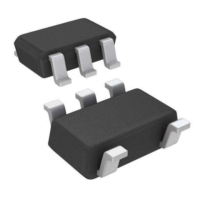
SOT23-5L
(Plastic package)
• Wireless battery chargers
• Chargers for portable equipment
• Precision current sources
• Wearable
Description
Pin connection
(Top view)
Out 1
The CS30 measures a small differential voltage
on a high-side shunt resistor and translates it into
a ground referenced output voltage. The gain is
internally fixed.
5 Vcc
Gnd 2
Vp 3
Wide input common-mode voltage range, low
quiescent current, and tiny SOT23 packaging
enable use in a wide variety of applications.
4 Vm
The input common-mode and power supply
voltages are independent. The common-mode
voltage can range from 2.8 to 30 V in operating
conditions and up to 60 V in absolute maximum
rating conditions.
Features
• Independent supply and input common-mode
voltages
• Wide common-mode operating range: 2.8 to
30 V
The current consumption below 300 µA and the
wide supply voltage range enable the power
supply to be connected to either side of the
current measurement shunt with minimal error.
• Wide common-mode surviving range: - 0.3 to
60 V (load-dump)
• Wide supply voltage range: 4 to 24 V
• Low current consumption: ICC max = 300 µA
• Internally fixed gain: 20 V/V, 50 V/V or 100 V/V
• Buffered output
Table 1. Device summary
Part number
Temperature range
Package
Packaging
CS30AL
CS30BL
-40°C to +125°C
SOT23-5L
CS30CL
March 2014
This is information on a product in full production.
DocID026040 Rev 1
Tape & reel
Marking
Gain
O104
20
O105
50
O106
100
1/18
www.st.com
�Contents
CS30
Contents
1
Application schematic and pin description . . . . . . . . . . . . . . . . . . . . . . 3
2
Absolute maximum ratings and operating conditions . . . . . . . . . . . . . 4
3
Electrical characteristics . . . . . . . . . . . . . . . . . . . . . . . . . . . . . . . . . . . . . 5
3.1
4
Electrical characteristics curves . . . . . . . . . . . . . . . . . . . . . . . . . . . . . . . . . 8
Parameter definitions . . . . . . . . . . . . . . . . . . . . . . . . . . . . . . . . . . . . . . . 12
4.1
Common mode rejection ratio (CMR) . . . . . . . . . . . . . . . . . . . . . . . . . . . . 12
4.2
Supply voltage rejection ratio (SVR) . . . . . . . . . . . . . . . . . . . . . . . . . . . . 12
4.3
Gain (Av) and input offset voltage (Vos) . . . . . . . . . . . . . . . . . . . . . . . . . . 12
4.4
Output voltage drift versus temperature . . . . . . . . . . . . . . . . . . . . . . . . . . 13
4.5
Output voltage accuracy . . . . . . . . . . . . . . . . . . . . . . . . . . . . . . . . . . . . . . 14
5
Application information . . . . . . . . . . . . . . . . . . . . . . . . . . . . . . . . . . . . . 15
6
Package information . . . . . . . . . . . . . . . . . . . . . . . . . . . . . . . . . . . . . . . . 16
7
Revision history . . . . . . . . . . . . . . . . . . . . . . . . . . . . . . . . . . . . . . . . . . . 17
2/18
DocID026040 Rev 1
�CS30
1
Application schematic and pin description
Application schematic and pin description
The CS30 high-side current sense amplifier features a 2.8 to 30 V input common-mode
range that is independent of the supply voltage. The main advantage of this feature is that it
allows high-side current sensing at voltages much greater than the supply voltage (VCC).
Figure 1. Application schematic
9VHQVH
,ORDG
���ĆWRĆ��Ć9Ć
5 VHQVH
9S
�
5J�
�ĆWRĆ��Ć9Ć
�
�
ORDG
9P
5J�
9&&
�
5J�
2XW
9RXWĆ Ć$YĆ[Ć9VHQVH
*QG
�
$0�����
Table 2 describes the function of each pin. The pin positions are shown in the illustration on
the cover page and in Figure 1 above.
Table 2. Pin description
Symbol
Type
Function
Out
Analog output
Output voltage, proportional to the magnitude of the sense voltage
Vp-Vm.
Gnd
Power supply
Ground line
VCC
Power supply
Positive power supply line
Vp
Analog input
Connection for the external sense resistor. The measured current
enters the shunt on the Vp side.
Vm
Analog input
Connection for the external sense resistor. The measured current
exits the shunt on the Vm side.
DocID026040 Rev 1
3/18
18
�Absolute maximum ratings and operating conditions
2
CS30
Absolute maximum ratings and operating conditions
Table 3. Absolute maximum ratings
Symbol
Vid
Vi
Parameter
Input pins differential voltage (Vp-Vm)
Input pin voltages (Vp and Vm)
(1)
(1)
Value
Unit
±60
V
-0.3 to 60
V
-0.3 to 25
V
VCC
DC supply voltage
Vout
DC output pin voltage(1)
-0.3 to VCC
V
Tstg
Storage temperature
-55 to 150
°C
Maximum junction temperature
150
°C
SOT23-5 thermal resistance junction to ambient
250
°C/Ω
HBM: human body model(2)
2.5
kV
150
V
1.5
kV
Tj
Rthja
ESD
MM: machine model
(3)
CDM: charged device
model(4)
1. Voltage values are measured with respect to the ground pin.
2. Human body model: a 100 pF capacitor is charged to the specified voltage, then discharged through a
1.5kΩ resistor between two pins of the device. This is done for all couples of connected pin combinations
while the other pins are floating.
3. Machine model: a 200 pF capacitor is charged to the specified voltage, then discharged directly between
two pins of the device with no external series resistor (internal resistor < 5 Ω). This is done for all couples of
connected pin combinations while the other pins are floating.
4. Charged device model: all pins plus package are charged together to the specified voltage and then
discharged directly to the ground.
Table 4. Operating conditions
Symbol
4/18
Parameter
VCC
DC supply voltage from Tmin to Tmax
Toper
Operational temperature range (Tmin to Tmax)
Vicm
Common mode voltage range
DocID026040 Rev 1
Value
Unit
4.0 to 24
V
-40 to 125
°C
2.8 to 30
V
�CS30
3
Electrical characteristics
Electrical characteristics
Table 5. Supply(1)
Symbol
ICC
Parameter
Total supply current
Test conditions
Min.
Vsense = 0 V
Tmin < Tamb < Tmax
Typ.
Max.
Unit
165
300
µA
1. Unless otherwise specified, the test conditions are Tamb = 25°C, VCC = 12 V, Vsense = Vp-Vm = 50 mV, Vm = 12 V, no load
on Out.
Table 6. Input(1)
Symbol
Parameter
Test conditions
Min.
Typ.
Max.
Unit
CMR
Common mode rejection
Variation of Vout versus Vicm
referred to input(2)
2.8 V < Vicm < 30 V
Tmin < Tamb < Tmax
90
105
dB
SVR
Supply voltage rejection
Variation of Vout versus VCC(3)
4.0 V < VCC < 24 V
Vsense = 30 mV
Tmin < Tamb < Tmax
90
105
dB
Vos
Input offset voltage(4)
Tamb = 25°C
Tmin < Tamb < Tmax
±0.2
±0.9
dVos/dT
Input offset drift vs. T
Tmin < Tamb < Tmax
-3
Ilk
Input leakage current
VCC = 0 V
Tmin < Tamb < Tmax
Iib
Input bias current
Vsense = 0 V
Tmin < Tamb < Tmax
5.5
±1.5
±2.3
mV
µV/°C
1
µA
8
µA
1. Unless otherwise specified, the test conditions are Tamb = 25°C, VCC = 12 V, Vsense = Vp-Vm = 50 mV, Vm = 12 V, no load
on Out.
2. See Section 4.1: Common mode rejection ratio (CMR) on page 12 for the definition of CMR.
3. See Section 4.2: Supply voltage rejection ratio (SVR) on page 12 for the definition of SVR.
4. See Section 4.3: Gain (Av) and input offset voltage (Vos) on page 12 for the definition of Vos.
DocID026040 Rev 1
5/18
18
�Electrical characteristics
CS30
Table 7. Output(1)
Symbol
Av
ΔAv
ΔVout/ΔT
Parameter
Test conditions
Gain
CS30A
CS30B
CS30C
Gain accuracy
Tamb = 25°C
Tmin < Tamb < Tmax
Output voltage drift vs. T(2)
Tmin < Tamb < Tmax
ΔVout/ΔIout Output stage load regulation
Min.
Typ.
Max.
20
50
100
V/V
±2.5
±4.5
0.4
-10 mA < Iout
很抱歉,暂时无法提供与“CS30BL”相匹配的价格&库存,您可以联系我们找货
免费人工找货- 国内价格 香港价格
- 1+20.503121+2.54632
- 10+15.2277810+1.89116
- 25+13.8986125+1.72609
- 100+12.43512100+1.54434
- 250+11.73770250+1.45773
- 500+11.31709500+1.40549
- 1000+10.970991000+1.36251
- 国内价格 香港价格
- 3000+10.406043000+1.29235
- 6000+10.199046000+1.26664
- 国内价格 香港价格
- 3000+9.227183000+1.14594
- 6000+9.035956000+1.12219
- 国内价格
- 1+17.55070
- 10+11.70050
- 30+9.75040


 工商网监
湘ICP备2023018690号
工商网监
湘ICP备2023018690号
