TDA7478
Single chip RDS demodulator
Features
■
Very high RDS demodulation quality with
improved digital signal processing
■
High performance, 57 kHz bandpass filter (8th
order)
■
Filter adjustment free and without external
components
■
Purely digital RDS demodulation without
external components
■
RDS signal quality output
■
4.332 MHz crystal oscillator (8.664 MHz
optionaL)
■
Low noise cmos technologY
■
Low radiation
*$3*36�����
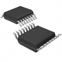
TSSOP16
Description
The TDA7478 recovers the additional inaudible
RDS information which is transmitted by FM radio
broadcasting stations and operates in accordance
with the EBU (European Broadcasting Union)
specifications.
Table 1.
The device is made up of two sections: a
cascaded antialiasing + switched capacitors 8th
bandpass filter for precise RDS band selection
and a demodulating section that performs the
extraction od RDS data stream (RDDA) and clock
(RDCL), to be further processed by a suitable
RDS decoder.
Output for RDS signal quality is also present.
Device summary
Order code
Package
E-TDA7478AD
Packing
Tube
TSSOP16
E-TDA7478ADTR
September 2013
Tape and reel
Doc 10679 Rev 4
1/11
www.st.com
11
�Contents
TDA7478
Contents
1
2
Block diagram and pins description . . . . . . . . . . . . . . . . . . . . . . . . . . . . 3
1.1
Block diagram . . . . . . . . . . . . . . . . . . . . . . . . . . . . . . . . . . . . . . . . . . . . . . . 3
1.2
Pins description . . . . . . . . . . . . . . . . . . . . . . . . . . . . . . . . . . . . . . . . . . . . . 4
Electrical specifications . . . . . . . . . . . . . . . . . . . . . . . . . . . . . . . . . . . . . . 5
2.1
Thermal data . . . . . . . . . . . . . . . . . . . . . . . . . . . . . . . . . . . . . . . . . . . . . . . 5
2.2
Absolute maximum ratings . . . . . . . . . . . . . . . . . . . . . . . . . . . . . . . . . . . . . 5
2.3
Electrical characteristics . . . . . . . . . . . . . . . . . . . . . . . . . . . . . . . . . . . . . . . 5
3
Output timing . . . . . . . . . . . . . . . . . . . . . . . . . . . . . . . . . . . . . . . . . . . . . . . 7
4
Oscillator controls (FSEL, OSEL) . . . . . . . . . . . . . . . . . . . . . . . . . . . . . . 8
5
Package information . . . . . . . . . . . . . . . . . . . . . . . . . . . . . . . . . . . . . . . . . 9
6
Revision history . . . . . . . . . . . . . . . . . . . . . . . . . . . . . . . . . . . . . . . . . . . 10
2/11
Doc 10679 Rev 4
�TDA7478
Block diagram and pins description
1
Block diagram and pins description
1.1
Block diagram
Figure 1.
Block diagram
&����S)
7��
�����0+]
26&,1
26&287
��
��
&����S)
��
�
03;
�QG�25'(5
$17,$/,$6,1*
),/7(5
���S)
�
26&,//$725�
',9,'(5
�
��
),/287
�WK�25'(5
6&�%$1'3$66
),/7(5
�
������+]
3//
��.+]�3//
�
�
��
96
48$/�'(7�
26(/
)6(/
5'&/
1�8�
48$/
���Q)
95()
�
�
�
32/$5,7<
%,3+$6(�'(&�
�
�
��P)
08;
',))��'(&2'(5
��
,17(*5$/
%,3+$6(�'(&�
�
�
7(67�/2*,&
5''$
70
��
*1'
(;75(6
Doc 10679 Rev 4
*$3*36�����
3/11
�Block diagram and pins description
1.2
TDA7478
Pins description
Figure 2.
Pin connection (top view)
48$/
�
��
5'&/
5''$
�
��
7��
95()
�
��
26&287
03;
�
��
26&,1
26(/
�
��
96
*1'
�
��
(;75(6
1�8�
�
��
70
),/287
�
�
)6(/
*$3*36�����
Table 2.
Pin #
Name
1
QUAL
Output for signal quality indication (High = good)
2
RDDA
RDS data output
3
VREF
Reference voltage
4
MPX
RDS input signal
5
OSEL
Oscillator selector pin:
– open, closed to VS = quartz oscillator
– closed to GND = external driven
6
GND
Ground
7
N.U.
Not Used (to be left open)
8
FILOUT
Description
Filter output
Frequency selector pin:
– open = 4.332 MHz
– closed to VS = 8.664 MHz
9
FSEL
10
TM
11
EXTRES
12
VS
Supply voltage
13
OSCIN
Oscillator input
14
4/11
Pins description
Test mode pin:
– open = normal operation
– closed to VS = testmode
Reset pin:
– open = run mode
– closed to VS = reset condition
OSCOUT Oscillator output
15
T57
16
RDCL
Testing output pin: 57 kHz clock output
RDS clock output 1187.5 Hz
Doc 10679 Rev 4
�TDA7478
Electrical specifications
2
Electrical specifications
2.1
Thermal data
Table 3.
Thermal data
Symbol
Rth j-case
2.2
Description
Thermal resistance junction-to-case
Unit
200
°C/W
Value
Unit
Absolute maximum ratings
Table 4.
Absolute maximum ratings
Symbol
2.3
Max.
Value
Parameter
VS
Supply voltage
-0.3 to 7
V
Top
Operating temperature range
-40 to 85
°C
Tstg
Storage temperature
-55 to 150
°C
Electrical characteristics
Tamb = 25°C, VS = 5V, unless otherwise specified.
Table 5.
Electrical characteristics
Symbol
Parameter
Test condition
Min.
Typ.
Max.
Unit
VS
Supply voltage
-
4.5
5
5.5
V
IS
Supply current
-
-
7.5
12.0
mA
Filter
fC
BW
G
A
Center frequency
-
56.6
57
57.4
kHz
3 dB bandwidth
-
2.5
3
3.5
kHz
Gain
f = 57 kHz
17
20
23
dB
Δf ± 4 kHz
-
22
-
dB
f = 38 kHz
-
60
-
dB
f = 67 kHz
-
45
-
dB
Attenuation
RI
Input impedance of MPX
-
-
120
-
KΩ
RL
Load impedance on FILOUT
-
1
-
-
MΩ
S/N
Signal to noise ratio
VIN = 3 mVRMS
30
40
-
dB
(1)
VIN
SRDS
MPX input signal
f = 19 kHz; T3 ≤ 40 dB
f = 57 kHz (RDS)
-
-
1000
50
mVRMS
mVRMS
RDS detection sensitivity
-
1
-
-
mVrms
Doc 10679 Rev 4
5/11
�Electrical specifications
Table 5.
TDA7478
Electrical characteristics (continued)
Symbol
Parameter
Test condition
Min.
Typ.
Max.
Unit
SARI
ARI detection sensitivity
-
3
-
-
mVrms
VREF
Reference
-
-
VS/2
-
V
Demodulator
Input pins (EXTRES, FSEL, TM)
all with internal pull down resistor
Input pin (OSEL)
with internal pull up resistor
IPD
Input current
VIN = 5 V (pull-down input)
15
-
30
μA
IPU
Input current
VIN = 0 V (pull-up input)
-25
-
-10
μA
VIH
Input voltage high
-
-
V
VIL
Input voltage low
-
-
0.7 · VS 0.8 · VS
0.2 · VS 0.3 · VS
V
Output pins (RDCL, RDDA, QUAL, T57)
VOH
Output voltage high
IL = 0.5 mA
4
4.6
-
V
VOL
Output voltage low
IL = 0.5 mA
-
0.4
1
V
Oscillator
VCLL
Input level OSCIN pin
OSEL = open circuit
-
-
1
V
Input level OSCIN pin
OSEL = open circuit
4
-
-
V
Amplitude OSCOUT
OSEL = open circuit
-
4.5
-
V
Amplitude OSCIN
(for external drive)
OSEL = GND, f = 4.332 MHz
OSEL = GND, f = 8.664 MHz
-
100
120
-
mVpp
mVpp
VCLH
VPP
1. The 3rd harmonic (57 kHz) must be less than -40 dB with respect to the input signal plus gain.
6/11
Doc 10679 Rev 4
�TDA7478
3
Output timing
Output timing
The RDS (1187.5Hz) output clock on RDCL line is synchronized to the incoming data.
According to the internal PLL lock condition data change can result on the falling or on the
rising clock edge. (see Figure 3). Whichever clock edge is used by the decoder (rising or
falling edge) the data will remain valid for 416.7 μs after the clock transition.
Figure 3.
RDS timing diagram
5'&/
&/2&.
/,1(
'$7$
/,1(
5''$
���V
WG
�����V
���V
���V
���V
*$3*36�����
Doc 10679 Rev 4
7/11
�Oscillator controls (FSEL, OSEL)
4
TDA7478
Oscillator controls (FSEL, OSEL)
Two different crystal frequencies can be used. The adaption of the internal clock divider to
the external crystal is achieved via the input pin FSEL. See the following table for reference.
Table 6.
Crystal frequencies
Crystal
4.332MHz
8.664MHz
FSEL (pin configuration)
connected to GND or open
connected to Vs
A special mode is introduced to reduce EMI. With pin OSEL connected to GND the internal
oscillator is switched off and an external sinusoidal frequency could be applied on OSCIN.
The peak to peak voltage of this signal can be reduced down to 60 mV.
In this mode the frequency selection via FSEL is still active.
Suggested values of C1 and C2 are shown in the following table.
Table 7.
8/11
C1 and C2 suggested value
Crystal
C1
C2
4.332MHz
8.664MHz
27pF
27pF
47pF
-
Doc 10679 Rev 4
�TDA7478
5
Package information
Package information
In order to meet environmental requirements, ST offers these devices in different grades of
ECOPACK® packages, depending on their level of environmental compliance. ECOPACK®
specifications, grade definitions and product status are available at: www.st.com.
ECOPACK® is an ST trademark.
Figure 4.
TSSOP16 mechanical data and package dimensions
PP
LQFK
',0�
0,1�
7
很抱歉,暂时无法提供与“E-TDA7478AD”相匹配的价格&库存,您可以联系我们找货
免费人工找货- 国内价格 香港价格
- 1+6.691491+0.86822
- 国内价格 香港价格
- 10+6.6914910+0.86822