ECMF02-2HSMX6
Datasheet
ESD protected common mode filter for USB3.2 interface
Features
•
Pin out, top view
D+ connector
1
6
D+ IC
D- connector
2
5
D- IC
3
4
To be left floating
GND
High common mode attenuation:
–
-10 dB at 300 MHz
–
-20 dB at 2.4 and 5 GHz
–
-15 dB from 500 MHz to 6 GHz
•
Compliant with USB3.2 gen 2 eye diagram
•
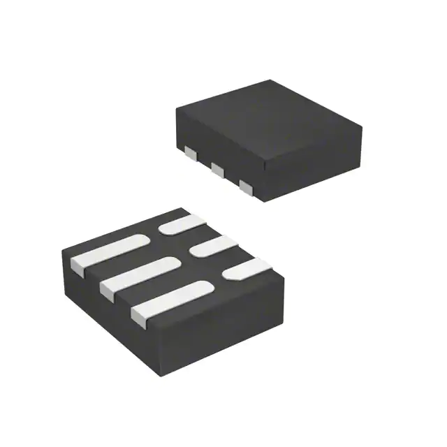
Small and thin package 1.5 x 1.7 x 0.5 mm
•
RoHS compliant
•
High reduction of parasitic elements through integration
•
ESD protection compliant with IEC 61000-4-2 level 4 standards (8 kV contact)
Benefits
•
Suppress the common mode noise but keep signal integrity
•
Low PCB space consumption
•
Save components count
•
Make the application robust against ESD strikes from external environment
Applications
Product status link
ECMF02-2HSMX6
Consumer and computer electronics featuring USB3.2 such as:
•
Mobile phones
•
Notebook, laptop
•
Portable devices
•
PND
Description
The ECMF02-2HSMX6 is a highly integrated common mode filter designed to
suppress EMI/RFI common mode noise on high speed differential serial buses like
USB3.2 transceiver.
DS9863 - Rev 4 - December 2021
For further information contact your local STMicroelectronics sales office.
www.st.com
�ECMF02-2HSMX6
Functional description
1
Functional description
The ECMF02-2HSMX6 is an ESD protected common mode filter especially designed for USB3.2 Tx/Rx
differential pair, for host and device. The USB3.2 is actually made of 3 differential pairs. The first differential
pair supports the high speed USB mode (also called USB2.0 mode). The 2 other differential pairs are used
to support the super speed USB mode in full duplex. Bit rate on super speed USB can reach 5 Gbps. The
ECMF02-2HSMX6 is able to filter the common mode noise from 300 MHz to 6 GHz, helping to make the
application compliant with the electromagnetic interference emission standard such as CISPR22 or FCC part 15,
or EN55022 and avoiding antenna desense on mobile phones, WiFi/Bluetooth, GPS,/GNSS frequencies. At the
same time, the ECMF02-2HSMX6 keeps the high speed signal integrity and provides an efficient ESD protection.
More application information available in following AN:
•
•
•
Application Note AN4356: "Antenna desense on handheld equipment"
Application Note AN4511: "Common Mode filters"
Application Note AN4540: "MHL link filtering and protection"
Figure 1. Functional diagram
D+ connector
1
6
D+ IC
D- connector
2
5
D- IC
3
4
To be left floating
GND
A typical application diagram is shown in Figure 2. ST offers a global approach to USB3.0 interface by providing a
comprehensive range of dedicated products.
Figure 2. Typical application diagram
Host
USB 2.0
VBUS
D+
High
Speed
Driver
DGND
VBUS
GND
VBUS
GND
D-
D-
D-
D-
D+
D+
D+
D+
GND
ID
ID
GND
ECMF02-4CMX8
+
USB 3.0
Super
Speed
Driver
+
SSTX+
SSTX -
D
6-
D1
D+
5
D
2+
I4D
GND
3
ECMF02-2HSMX6
SSR X+
SSR X -
-1
D
-6
D
+2
D
+5D
D3
NG
4
DI
ECMF02-2HSMX6
D
6-
D1
-1
D
-6
D
D
2+
+2
D
+5D
I4D
G3ND
D3
NG
4
DI
CONNECTOR
VBUS USB 2.0
D+
High
DSpeed
GND Driver
ECMF02-4CMX8
D+
5
ECMF02-2HSMX6
DS9863 - Rev 4
Hub/device
USB 3.0 cable
SSTX+
+
SSTX USB 3.0
Super
Speed
Driver
SSR X+
+
SSR X -
ECMF02-2HSMX6
CONNECTOR
page 2/13
�ECMF02-2HSMX6
Characteristics
2
Characteristics
Table 1. Absolute maximum ratings (Tamb = 25 °C)
Symbol
Parameter
Value
Unit
Contact discharge
±8
kV
Air discharge
±15
IEC 61000-4-2:
VPP
Peak pulse voltage
IDC
Maximum DC current
Top
Operating ambient temperature range
Tj
Tstg
100
mA
-55 to +125
Maximum junction temperature
+125
Storage temperature range
°C
-55 to +150
Figure 3. Electrical characteristics (definitions)
Table 2. Electrical characteristics (Tamb = 25 °C)
Symbol
DS9863 - Rev 4
Test conditions
VBR
IR = 1 mA
IRM
VRM = 3 V
RDC
DC serial resistance
Min.
Typ.
Max.
6
Unit
V
7
100
nA
9
Ω
page 3/13
�ECMF02-2HSMX6
Characteristics (curves)
2.1
Characteristics (curves)
Figure 4 shows that USB3.0 devices and cables can interfere with radio frequency devices operating between
700 MHz and 5 GHz.
Figure 4. USB3.2 frequency radiation measured with
current loop
-70
Figure 5. Differential and common mode impedance
versus frequency
dB
Skew
-75
-80
-85
-90
-95
-100
0
Frequency (GHz)
0,5
1
1,5
2
2,5
3
3,5
4
4,5
5
5,5
6
Figure 6. Differential attenuation versus frequency
Figure 7. Common mode attenuation versus frequency
Figure 8. Return loss versus frequency (Z0 DIFF = 100 Ω SDD11)
Figure 9. Return loss versus frequency (Z0 DIFF = 100 Ω SDD22)
DS9863 - Rev 4
page 4/13
�ECMF02-2HSMX6
Characteristics (curves)
Figure 10. Typical ESD response to IEC 61000-4-2 +8kV
contact
Figure 11. Typical ESD response to IEC 61000-4-2 -8kV
contact
Figure 12. USB2.0 (480 Mbps) eye diagram without device
Figure 13. USB2.0 (480 Mbps) eye diagram with device
Figure 14. USB 3.2 Gen 1 - 5.0 Gbps eye diagram without
ECMF02-2HSMX6 (with type C connector, reference cable
and equalizer)
Figure 15. USB 3.2 Gen 1 - 5.0 Gbps eye diagram with
ECMF02-2HSMX6 (with type C connector, reference cable
and equalizer)
DS9863 - Rev 4
page 5/13
�ECMF02-2HSMX6
Characteristics (curves)
Figure 16. USB 3.2 Gen 2 - 10.0 Gbps eye diagram without
Figure 17. USB 3.2 Gen 2 - 10.0 Gbps eye diagram with
ECMF02-2HSMX6 (with type C connector, reference cable, ECMF02-2HSMX6 (with type C connector, reference cable,
equalizer with ADC = 6 dB and DFE)
equalizer with ADC = 6 dB and DFE)
Figure 18. Display Port HBR2 5.4 Gbps eye diagram
without ECMF02-2HSMX6
DS9863 - Rev 4
Figure 19. Display Port HBR2 5.4 Gbps eye diagram with
ECMF02-2HSMX6
page 6/13
�ECMF02-2HSMX6
Package information
3
Package information
In order to meet environmental requirements, ST offers these devices in different grades of ECOPACK packages,
depending on their level of environmental compliance. ECOPACK specifications, grade definitions and product
status are available at: www.st.com. ECOPACK is an ST trademark.
3.1
QFN-6L package information
Figure 20. QFN-6L package outline
Table 3. QFN-6L mechanical data
Symbol
DS9863 - Rev 4
Dimesions (milimeters)
Min.
Typ.
Max.
A
0.45
0.50
0.55
A1
0.00
0.02
0.05
b
0.18
0.25
0.30
D
1.65
1.70
1.75
E
1.45
1.50
1.55
e
0.45
0.50
0.55
L1
0.35
0.45
0.55
L2
0.65
0.75
0.85
page 7/13
�ECMF02-2HSMX6
Packing information
3.2
Packing information
Figure 21. Marking
Note:
The marking can be rotated to differentiate assembly location. Refer to Table 4 for xx definition.
Figure 22. Tape outline
DS9863 - Rev 4
page 8/13
�ECMF02-2HSMX6
PCB assembly recommendation
4
PCB assembly recommendation
4.1
Footprint
SMD footprint design is recommended.
Figure 23. Footprint in mm
4.2
Stencil opening design
Stencil opening thickness: 100 μm
Figure 24. Stencil opening recommendations
4.3
Solder paste
1.
2.
3.
4.
DS9863 - Rev 4
Halide-free flux, qualification ROL0 according to ANSI/J-STD-004.
“No clean” solder paste recommended.
Tack force high enough to resist component displacement during PCB movement.
Particles size 20-38 µm per IPCJ STD-005.
page 9/13
�ECMF02-2HSMX6
Placement
4.4
Placement
1.
2.
3.
4.
4.5
PCB design preference
1.
2.
4.6
It is recommended to use leads recognition instead of package outline for accurate placement on footprint
with adequate resolution tool.
Tolerance of ±50 µm (25% offset allowed on the smallest dimension of the smallest pad) is recommended.
3.5 N placement force is recommended. Too much placement force can lead to squeezed out solder paste
and cause solder joints to short. Too low placement force can lead to insufficient contact between package
and solder paste that could cause open solder joints or badly centered packages.
For assembly, a perfect supporting of the PCB (all the more on flexible PCB) is recommended during solder
paste printing, pick and place and reflow soldering by using optimized tools.
Any via around or inside the footprint area must be closed to avoid solderpaste migration in the via.
Position and dimensions of the tracks should be well balanced. A symmetrical layout is recommended to
prevent assembly troubles.
Reflow profile
Figure 25. ST ECOPACK recommended soldering reflow profile for PCB mounting
250
240-245 °C
Temperature (°C)
-2 °C/s
2 - 3 °C/s
60 sec
(90 max)
200
-3 °C/s
150
-6 °C/s
100
0.9 °C/s
50
Time (s)
0
Note:
DS9863 - Rev 4
30
60
90
120
150
180
210
240
270
300
Minimize air convection currents in the reflow oven to avoid component movement. Maximum soldering profile
corresponds to the latest IPC/JEDEC J-STD-020.
page 10/13
�ECMF02-2HSMX6
Ordering information
5
Ordering information
Figure 26. Ordering information scheme
ECMF 02 - 2
HS MX6
Function
ESD common mode filter
Number of lines
02 = 2 lines
Number of ESD protected lines
2 = 2 ESD protected lines
Version
HS = High speed lines
Package
MX6 = µQFN-6L
Table 4. Ordering information
DS9863 - Rev 4
Order code
Marking
Package
Weight
Base qty.
Delivery mode
ECMF02-2HSMX6
KR
µQFN-6L
3.4 mg
3000
Tape and reel
page 11/13
�ECMF02-2HSMX6
Revision history
Table 5. Document revision history
Date
Version
Changes
13-Nov-2013
1
Initial release.
25-Aug-2014
2
Inserted Figure 10: Differential (ZDD21) and common mode (ZCC21)
impedance versus frequency.
13-Dec-2017
3
Updated Table 1.
20-Dec-2021
4
Updated title description, Section 2.1 Characteristics (curves) and removed
PCB layout chapter.
Minor text changes.
DS9863 - Rev 4
page 12/13
�ECMF02-2HSMX6
IMPORTANT NOTICE – PLEASE READ CAREFULLY
STMicroelectronics NV and its subsidiaries (“ST”) reserve the right to make changes, corrections, enhancements, modifications, and improvements to ST
products and/or to this document at any time without notice. Purchasers should obtain the latest relevant information on ST products before placing orders. ST
products are sold pursuant to ST’s terms and conditions of sale in place at the time of order acknowledgement.
Purchasers are solely responsible for the choice, selection, and use of ST products and ST assumes no liability for application assistance or the design of
Purchasers’ products.
No license, express or implied, to any intellectual property right is granted by ST herein.
Resale of ST products with provisions different from the information set forth herein shall void any warranty granted by ST for such product.
ST and the ST logo are trademarks of ST. For additional information about ST trademarks, please refer to www.st.com/trademarks. All other product or service
names are the property of their respective owners.
Information in this document supersedes and replaces information previously supplied in any prior versions of this document.
© 2021 STMicroelectronics – All rights reserved
DS9863 - Rev 4
page 13/13
�
很抱歉,暂时无法提供与“ECMF02-2HSMX6”相匹配的价格&库存,您可以联系我们找货
免费人工找货- 国内价格 香港价格
- 1+4.988451+0.64534
- 国内价格
- 1+5.74070
- 10+4.78400
- 30+3.82720
- 100+3.18930