EV-VNQ5E160K
VNQ5E160K evaluation board
Data brief − production data
Features
Parameter
Symbol
Value
Unit
Max transient supply
voltage
VCC
41
V
Operating voltage range
VCC
4.5 to 28
V
Max On-State resistance
RON
160
mΩ
Current limitation (typ)
ILIMH
10
A
Off-state supply current
IS
2
µA(1)
active low digital status pin is associated with
every output channel that provides enhanced
diagnostic functions including fast detection of
overload and short-circuit to ground,
overtemperature indication, short-circuit to VCC
diagnosis and ON-state and OFF-state open-load
detection.
The diagnostic feedback of the whole device can
be disabled by pulling the STAT_DIS pin up, thus
allowing wired-ORing with similar devices.
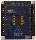
Figure 1.
VNQ5E160K evaluation board
Table 1.
Device summary
1. Typical value with all loads connected.
■
Simple single IC application board dedicated
for VNQ5E160K-E
■
Provides thermal heat-sinking for ease of use
in prototyping
■
Provides electrical connectivity for easy
prototyping
Description
EV-VNQ5E160K provides you an easy way to
connect ST’s surface mounted VIPower® drivers
into your existing prototype circuitry. This
evaluation board comes pre-assembled with
VNQ5E160K-E high-side driver.
The VNQ5E160K-E is a quad channel
high-side driver manufactured using ST
proprietary VIPower M0-5 technology and housed
in PowerSSO-24 package. The VNQ5E160K-E is
designed to drive automotive grounded loads,
providing protection, diagnostics and easy 3 V
and 5 V CMOS-compatible interface with any
microcontroller.
The device integrates advanced protective
functions such as load current limitation, inrush
and overload active management by power
limitation, overtemperature shut-off with autorestart and overvoltage active clamp. A dedicated
September 2013
Order code
EV-VNQ5E160K
Reference
VNQ5E160K evaluation board
Doc ID 023996 Rev 2
This is information on a product in full production. For further information contact your local STMicroelectronics sales
office.
1/9
www.st.com
1
�Design recommendations
1
EV-VNQ5E160K
Design recommendations
This evaluation board provides mounting solution and some heat sinking capability for
prototype development, but there are still external components that are required to make
these devices work in any application. For further information on how the evaluation board
has to be used you can refer to the AN4212 (see Appendix A: Reference documents).
Figure 2 illustrates the necessary components for any application.
Figure 2.
VNQ5E160K evaluation board
9&&��%DWWHU\�
��9
��9
��9
��9
����O'
5"#
5"#
��N
��N
��N
��N
��
�
���O'
�
,1387�
/54054�
�
*1'
287387�
�
,1387�
287387�
67$786�
287387�
,1387�
287387�
��N
67$786�
��N
�
,1387�
��N
�
67$786�
��
9&&
��N
,1387�
�
��N
67$786�
�
��N
,1387�
�
��N
��
67$786�
287387�
67$786�
,1387�
��N
�7$%�
��
���O'
��
��
287387�
67$786�
287387�
,1387�
287387�
67$786�
287387�
67$7B',6
287387�
9&&
287387�
9�
/RDGV
��
9�
/RDGV
��
���O'
��
��
9�
/RDGV
��
���O'
��N
67$7B',6
��
��
��
��
��N
9�
/RDGV
2SWLRQDO
�N
6PDOO�6LJQDO
'LRGH
)RU�5HYHUVH
%DWWHU\�3URWHFWLRQ
*$3*&)7�����
ST has produced a user manual for safe designs using ST’s VIPower devices. This is
UM1556 (see Appendix A: Reference documents). UM1556 is a VIPower Hardware design
guide that provides all necessary information to successfully design your circuit using our
VIPower drivers.
All designs have different needs and requirements. Whatever design you decide to use, it
will still need to be verified in order to meet your application specifications. ST implies no
guarantee or warranty (see Appendix A: Reference documents).
2/9
Doc ID 023996 Rev 2
�EV-VNQ5E160K
2
Thermal data
Thermal data
Table 2.
VNQ5E160K-E thermal data
Symbol
Rthj-amb
Table 3.
Parameter
Thermal resistance junction-ambient (MAX)
Max. value
Unit
30.5
°C/W
PCB specifications
Parameter
Value
Unit
38 x 43
mm
Number of Cu layer
2
—
Layer Cu thickness
70
µm
1.6 +/- 10%
mm
Board Material
FR4
—
Thermal vias separation
1.2
mm
0.3 /- 0.08
mm
Board dimensions
Board finish thickness
Thermal vias diameter
Doc ID 023996 Rev 2
3/9
�Board connector reference
3
4/9
EV-VNQ5E160K
Board connector reference
Figure 3.
Board layout
Table 4.
Board connector specification
Connector
Board lead number
Device pin function(1)
J1
TAB
VCC
J1
1
VCC
J1
2
GND
J1
3
INPUT1
J1
4
STATUS1
J1
5
INPUT2
J1
6
STATUS2
J1
7
INPUT3
J1
8
STATUS3
J1
9
INPUT4
J1
10
STATUS4
J1
11
STAT_DIS
J1
12
VCC
J2
TAB
VCC
J2
13
OUTPUT4
J2
14
OUTPUT4
J2
15
OUTPUT4
Doc ID 023996 Rev 2
�EV-VNQ5E160K
Board connector reference
Table 4.
Board connector specification (continued)
Connector
Board lead number
Device pin function(1)
J2
16
OUTPUT3
J2
17
OUTPUT3
J2
18
OUTPUT3
J2
19
OUTPUT2
J2
20
OUTPUT2
J2
21
OUTPUT2
J2
22
OUTPUT1
J2
23
OUTPUT1
J2
24
OUTPUT1
1. For further clarification on pin functions please refer to the related datasheet (see Appendix A: Reference
documents).
Doc ID 023996 Rev 2
5/9
�Package information
EV-VNQ5E160K
4
Package information
4.1
ECOPACK® packages
In order to meet environmental requirements, ST offers these devices in different grades of
ECOPACK® packages, depending on their level of environmental compliance. ECOPACK®
specifications, grade definitions and product status are available at: www.st.com.
ECOPACK® is an ST trademark.
6/9
Doc ID 023996 Rev 2
�EV-VNQ5E160K
Reference documents
Appendix A
Reference documents
1.
Quad channel high side driver for automotive applications (VNQ5E160K-E,
DocID 14471)
2.
VIPower M0-5 and M0-5Enhanced high-side drivers (UM1556, DocID 023520)
3.
PowerSSO-24 devices evaluation bord (AN4212, DocID 023983)
4.
Evaluation Product Licence Agreement on www.st.com
Doc ID 023996 Rev 2
7/9
�Revision history
EV-VNQ5E160K
Revision history
Table 5.
8/9
Document revision history
Date
Revision
Changes
29-Nov-2012
1
Initial release.
16-Sep-2013
2
Updated disclaimer.
Doc ID 023996 Rev 2
�EV-VNQ5E160K
Please Read Carefully:
Information in this document is provided solely in connection with ST products. STMicroelectronics NV and its subsidiaries (“ST”) reserve the
right to make changes, corrections, modifications or improvements, to this document, and the products and services described herein at any
time, without notice.
All ST products are sold pursuant to ST’s terms and conditions of sale.
Purchasers are solely responsible for the choice, selection and use of the ST products and services described herein, and ST assumes no
liability whatsoever relating to the choice, selection or use of the ST products and services described herein.
No license, express or implied, by estoppel or otherwise, to any intellectual property rights is granted under this document. If any part of this
document refers to any third party products or services it shall not be deemed a license grant by ST for the use of such third party products
or services, or any intellectual property contained therein or considered as a warranty covering the use in any manner whatsoever of such
third party products or services or any intellectual property contained therein.
UNLESS OTHERWISE SET FORTH IN ST’S TERMS AND CONDITIONS OF SALE ST DISCLAIMS ANY EXPRESS OR IMPLIED
WARRANTY WITH RESPECT TO THE USE AND/OR SALE OF ST PRODUCTS INCLUDING WITHOUT LIMITATION IMPLIED
WARRANTIES OF MERCHANTABILITY, FITNESS FOR A PARTICULAR PURPOSE (AND THEIR EQUIVALENTS UNDER THE LAWS
OF ANY JURISDICTION), OR INFRINGEMENT OF ANY PATENT, COPYRIGHT OR OTHER INTELLECTUAL PROPERTY RIGHT.
ST PRODUCTS ARE NOT DESIGNED OR AUTHORIZED FOR USE IN: (A) SAFETY CRITICAL APPLICATIONS SUCH AS LIFE
SUPPORTING, ACTIVE IMPLANTED DEVICES OR SYSTEMS WITH PRODUCT FUNCTIONAL SAFETY REQUIREMENTS; (B)
AERONAUTIC APPLICATIONS; (C) AUTOMOTIVE APPLICATIONS OR ENVIRONMENTS, AND/OR (D) AEROSPACE APPLICATIONS
OR ENVIRONMENTS. WHERE ST PRODUCTS ARE NOT DESIGNED FOR SUCH USE, THE PURCHASER SHALL USE PRODUCTS AT
PURCHASER’S SOLE RISK, EVEN IF ST HAS BEEN INFORMED IN WRITING OF SUCH USAGE, UNLESS A PRODUCT IS
EXPRESSLY DESIGNATED BY ST AS BEING INTENDED FOR “AUTOMOTIVE, AUTOMOTIVE SAFETY OR MEDICAL” INDUSTRY
DOMAINS ACCORDING TO ST PRODUCT DESIGN SPECIFICATIONS. PRODUCTS FORMALLY ESCC, QML OR JAN QUALIFIED ARE
DEEMED SUITABLE FOR USE IN AEROSPACE BY THE CORRESPONDING GOVERNMENTAL AGENCY.
Resale of ST products with provisions different from the statements and/or technical features set forth in this document shall immediately void
any warranty granted by ST for the ST product or service described herein and shall not create or extend in any manner whatsoever, any
liability of ST.
ST and the ST logo are trademarks or registered trademarks of ST in various countries.
Information in this document supersedes and replaces all information previously supplied.
The ST logo is a registered trademark of STMicroelectronics. All other names are the property of their respective owners.
© 2013 STMicroelectronics - All rights reserved
STMicroelectronics group of companies
Australia - Belgium - Brazil - Canada - China - Czech Republic - Finland - France - Germany - Hong Kong - India - Israel - Italy - Japan Malaysia - Malta - Morocco - Philippines - Singapore - Spain - Sweden - Switzerland - United Kingdom - United States of America
www.st.com
Doc ID 023996 Rev 2
9/9
�