EVAL6470H
Fully integrated stepper motor driver mounting the L6470
Data brief
Description
The EVAL6470H demonstration board is a fully
integrated microstepping motor driver. In
combination with the STEVAL-PCC009V2
communication board and the SPIN evaluation
software, the board allows the user to investigate
all the features of the L6470 device. In particular,
the board can be used to check the voltage mode
driving and to regulate the L6470 parameters in
order to fit the application requirements.
The EVAL6470H supports the daisy chain
configuration making it suitable for the evaluation
of the L6470 in multi motor applications.
Features
Voltage range from 8 V to 45 V
Phase current up to 3 Arms.
SPI with daisy chain feature
Socket for external resonator or crystal
SW input
FLAG and BUSY LED indicators
Adjustable supply voltage compensation
Suitable to be used in combination with
STEVAL-PCC009V2
March 2015
DocID022736 Rev 3
For further information contact your local STMicroelectronics sales office.
1/11
www.st.com
�Board description
EVAL6470H
Board description
Table 1. EVAL6470H specifications
Parameter
Value
Supply voltage (VS)
8 to 45 V
Maximum output current (each phase)
3 Ar.m.s.
Logic supply voltage (VREG)
Externally supplied: 3.3 V, internally supplied: 3 V
(typ.)
Logic interface voltage (VDD)
Externally supplied: 3.3 V or 5 V, internally supplied:
VREG
Low level logic inputs voltage
0V
High level logic input voltage
VDD(1)
Operating temperature
-25 to +125 °C
L6470H thermal resistance junction to ambient
21 °C/W (typ.)
1. All logic inputs are 5 V tolerant.
Figure 1. Jumpers and connectors location
FLAG LED
(Red)
Application reference
area
Power supply connector
(8 V - 45 V)
BUSY LED
(Amber)
JP1: VDD supply from
master SPI connector
JP3: Daisy chain
termination
Slave SPI
connector
Master SPI
connector
JP2: VDD to VREG
connection
External switch connector
(SW input)
Motor supply voltege
compensation
partitioning regulation
(ADCIN input)
OSCIN/OSCOUT
connector
Phase A connector
Phase B connector
AM11330v1
2/11
DocID022736 Rev 3
�EVAL6470H
Board description
Table 2. Jumpers and connectors description
Name
Type
Function
J1
Power supply
Motor supply voltage
J5
Power output
Bridge A outputs
J6
Power output
Bridge B outputs
J2
SPI connector
Master SPI
J3
SPI connector
Slave SPI
J4
NM connector
OSCIN and OSCOUT pins
J7
NM connector
External switch input
TP1 (VS)
Test point
Motor supply voltage test point
TP4 (VDD)
Test point
Logic interface supply voltage test point
TP5 (VREG)
Test point
Logic supply voltage/L6470 internal regulator test point
TP6 (GND)
Test point
Ground test point
TP2 (STCK)
Test point
Step clock input test point
TP3 (STBY/RES)
Test point
Standby/reset input test point
TP7 (FLAG)
Test point
FLAG output test point
TP8 (BUSY/SYNC)
Test point
BUSY/SYNC output test point
Table 3. Master SPI connector pinout (J10)
Pin number
Type
Description
1
Open drain output
L6470 BUSY/SYNC output
2
Open drain output
L6470 FLAG output
3
Ground
Ground
4
Supply
EXT_VDD (can be used as external logic power supply)
5
Digital output
SPI “Master In Slave Out” signal (connected to L6470 SDO
output through daisy chain termination jumper JP2)
6
Digital input
SPI serial clock signal (connected to L6470 CK input)
7
Digital input
SPI “Master Out Slave In” signal (connected to L6470 SDI
input)
8
Digital input
SPI slave select signal (connected to L6470 CS input)
9
Digital input
L6470 step-clock input
10
Digital input
L6470 STBY/RST input
DocID022736 Rev 3
3/11
11
�Board description
EVAL6470H
Table 4. SPI connector pinout (J11)
4/11
Pin number
Type
Description
1
Open drain output
L6470 BUSY/SYNC output
2
Open drain output
L6470 FLAG output
3
Ground
Ground
4
Supply
EXT_VDD (can be used as external logic power supply)
5
Digital output
SPI “Master In Slave Out” signal (connected to pin 5 of J10)
6
Digital input
SPI serial clock signal (connected to L6470 CK input)
7
Digital input
SPI “Master Out Slave In” signal (connected to L6470 SDO
output)
8
Digital input
SPI slave select signal (connected to L6470 CS input)
9
Digital input
L6470 step-clock input
10
Digital input
L6470 STBY/RST input
DocID022736 Rev 3
��
�
5�
�N�
5�
���.
5�
��N�
�
DocID022736 Rev 3
�
�
/('�5('
�
)/$*
���
�
�
/('�$0%(5
'/�
%86<
6:
1�0�
5�
���
��
���
5�
'*1'
�
�
��
-�
&6
&.
6',
6'2
�
&�
��Q)���9
�
96
287�%
287�%
287�$
287�$
&��
��Q)��9�
6:
73�
&�
���Q)��9�
�
��
��
��
73�
9''
*1'
�
&�
��X)��9�
(;7B9''
&.
Q&6
67%
很抱歉,暂时无法提供与“EVAL6470H”相匹配的价格&库存,您可以联系我们找货
免费人工找货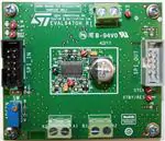


 工商网监
湘ICP备2023018690号
工商网监
湘ICP备2023018690号
