EVSPIN32G4, EVSPIN32G4NH
Data brief
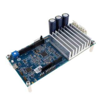
STSPIN32G4 demonstration board for three-phase brushless motors
Features
•
•
•
Input bus voltage from 10 V to 75 V with dedicated monitoring
Power stage based on the STL110N10F7 power MOSFETs with output current
up to 20 Arms (with heatsink mounted) and protected to overcurrent conditions
STSPIN32G4, high performance three-phase motor controller with embedded
STM32G431 MCU:
32-bit ARM® Cortex®-M4 MCU+FPU
Up to 170 MHz clock frequency
CORDIC mathematical hardware accelerator for trigonometric functions
128 kB Flash memory with proprietary code readout protection (PCROP),
securable memory area, 1 kB OTP
–
32 kB SRAM memory with HW parity check
–
2 x advanced timers for motor control, 16-bit with up to 6 x PWM channels
each
–
8 x general purpose timers
–
2 x ADCs 12-bit resolution (up to 19 channels) with 4 Msps conversion rate
–
4 x 12-bit DAC channels
–
4 x ultra-fast rail-to-rail comparators
–
3 x rail-to-rail operational amplifiers usable also in PGA mode
–
Internal high precision voltage reference
–
Up to 40 GPIOs
–
Full set of interfaces: I2C, SPI, UART and CAN
–
VCC buck converter up to 200 mA, with programmable output and
embedded MOSFET
–
3.3 V LDO linear regulator up to 150 mA
–
Low quiescent linear regulator for MCU supply in standby mode
–
Regulators with full set of protection features; thermal shutdown, shortcircuit and overload protections
–
75 V rated gate drivers with 1 A sink/source current and embedded
bootstrap diodes
–
Drain-source voltage sensing of each power MOSFET
Three-shunt or single-shunt configurable current sensing
Digital Hall sensor and quadrature encored input
ST-LINK/V2 programmer and debugger
Arduino UNO connector
Predisposition for CAN bus
NTC sensor for power stage temperature monitoring
–
–
–
–
Product status link
EVSPIN32G4
EVSPIN32G4NH
STSPIN32G4
•
•
•
•
•
•
Application
•
•
•
•
Industrial and home automation
Home appliances such as vacuum cleaners, dryers and cleaning robots
Servo drives and e-bikes
Service and automation robots
DB4420 - Rev 1 - March 2021
For further information contact your local STMicroelectronics sales office.
www.st.com
�EVSPIN32G4, EVSPIN32G4NH
•
•
•
Power and garden tools
Pumps and fans
Drones and aeromodelling
Description
The EVSPIN32G4 is a demonstration board based on the STSPIN32G4 system in
package and STL110N10F7 power MOSFETs. The STSPIN32G4 integrates in a 9x9
mm VFQFPN package, a triple high-performance half-bridge gate driver with a rich
set of programmable features and one mixed signal STM32G431 microcontroller.
The integrated operational amplifiers for current sensing, the drain-source voltage
sensing of each power MOSFET and comparators for overcurrent protection make it
a fully integrated solution for motor control.
Thanks to the integrated voltage regulators both the gate driver and control logic
supplies can be generated starting from the motor supply without dedicated circuitry.
The board ensures a full evaluation of the STSPIN32G4 and is designed for
driving three-phase brushless DC motors and provides an easy-to-use solution for
STSPIN32G4 evaluation in different applications such as power tools, e-Bikes, fans,
and home appliances.
The board can be configured in three-shunt or single-shunt supporting both sensorless and sensor-based control algorithms.
The Arduino connector enables the EVSPIN32G4 to be interfaced with expansion
boards, such as MEMS sensors or Bluetooth transceivers, while predisposition for
CAN bus allows interconnection with master or slave modules to build complex
motion control systems.
The on-board ST-LINK/V2 programmer speeds up and simplifies the debugging of
microcontroller firmware.
DB4420 - Rev 1
page 2/18
�EVSPIN32G4, EVSPIN32G4NH
Specifications
1
Specifications
Table 1. EVSPIN32G4 specifications
Parameter
Supply voltage
Maximum output current with heatsink (EVSPIN32G4)
Maximum output current without heatsink (EVSPIN32G4NH)
Value
Nominal
From 10 V to 75 V
Peak
35 A
Continuous(1)
20 Arms
Peak
25 A
Continuous(1)
15 Arms
1. Maximum current at ambient temperature of 25°C. Actual maximum current could be limited by power dissipation.
Ratings of the board can be found in Table 1. The EVSPIN32G4NH is the board version without heatsink.
The schematic of the EVSPIN32G4 evaluation board (from Figure 1 to Figure 6) and bill of material (Table 2) are
reported below.
DB4420 - Rev 1
page 3/18
�EVSPIN32G4, EVSPIN32G4NH
Specifications
Figure 1. EVSPIN32G4 schematic (1 of 6): STSPIN32G4
C4
6.8pF
X1
24.000MHZ
GND
C5
6.8pF
VCC
0
R7
0
R6
GND
VDD
VDD
SW
PF 1
VDD
VDDA
1
R8
0
C8
1uF
L1
18 uH
VDDA
2
VCC
C1
10 uF
25V
VBUS PA 0
OPP1 PA 1
OPO1 PA 2
OPN1 PA 3
C10
1uF
VREF+
VREF+
VDD
VBAT
USER1 PC1 3
CAN_SHDNPC1 4
PC1 5
OSC_IN PF 0
OSC_OUT PF 1
nRST P G10
VOUT1 PC 0
VOUT2 PC 1
VOUT3 PC 2
PC 3
R9
0
C9
100 nF
C2
220 nF
100V
C11
100 nF
1
2
3
4
5
6
7
8
9
10
11
12
13
14
15
16
R1
0
REG3V3/VDD
VBAT
PC13
PC14
PC15
PF0
PF1
PG10
PC0
PC1
PC2
PC3
PA0
PA1
PA2
PA3
VBAT
VM
HALL3
HALL2
HALL1
SWO/JTDO
PB 9
PB 8
PB 7
PB 6
PB 5
PB 4
PB 3
PD 2
SCRE F
VREGIN
VCC
SW
PA1 5 JTDI
PA1 4 SWCLK/JTCK
PA1 3 SWDIO/JTMS
64
63
62
61
60
59
58
57
56
55
54
53
52
51
50
49
1
2
PF 0
D1
STPS1H100A
C7
100 nF
VBAT
VREGIN
4
C12
100 nF
TP1
GND
VSS
U1
48
47
46
45
44
43
42
41
40
39
38
37
36
35
STSPIN32G4
PA12
PA11
PA10
PA9
PA8
GHS1
OUT1
BOOT1
GHS2
OUT2
BOOT2
GHS3
OUT3
BOOT3
J2
DIS
VDSMON
CAN TX
CAN RX
UART RX
UART TX
Open (deafult): SC
protection enabled
Closed: SC
protection disabled
J1
OPEN
PA1 2
PA1 1
PA1 0
PA 9
PA 8
GHS 1
OUT1
BOO T1
GHS 2
OUT2
BOO T2
GHS 3
OUT3
BOO T3
1
2
SCRE F
VDD
1
3
5
7
9
J3
C3
N.M.
2
4
6
8
10
VDD
PA1 3
PA1 4
PB 3
PA1 5
P G10
R2
22k
1%
R3
10k
1%
page 4/18
DB4420 - Rev 1
C6
10 uF
65
2
RE GIN
VCC
SW
VM
PB 9
PB 8
PB 7
PB 6
PB 5
PB 4
PB 3
PD 2
SCRE F
PA1 5
PA1 4
PA1 3
PA 4
PA 5
PA 6
PA 7
PC 4
PC 5
PB 0
PB 1
PB 2
VREFP
VDDA
PB1 0
GLS1
GLS2
GLS3
P GND
17
18
19
20
21
22
23
24
25
26
27
28
29
30
31
32
PA 4
PA 5
PA 6
PA 7
PC 4
PC 5
PB 0
PB 1
PB 2
VREF+
VDDA
USER2 PB1 0
GLS1
GLS2
GLS3
DAC1
DAC2
OPO2
OPP2
NTC
OPN2
OPP3
OPO3
OPN3
1
3
�EVSPIN32G4, EVSPIN32G4NH
Specifications
Figure 2. EVSPIN32G4 schematic (2 of 6): Power stage
GHS1
BOOT1
OUT1
GLS1
GND
TP2
D2
C16
1uF
25V
D5
BAT48
R13
33
R19
0
BAT48
R25
33
VSHUNT1P
R10
0
R16
N.M.
R22
0
1
R28
N.M.
R31
10m
1%
3W
VSHUNT1N
4
4
2
C13
1 2 3
5 6 7 8
U
1 2 3
5 6 7 8
VM
Q1
Q4
R32
10m
1%
3W
220 nF
100V
GHS2
BOOT2
OUT2
GLS2
JP1
OPEN
D3
C17
1uF
25V
D6
BAT48
R14
33
R20
0
BAT48
R26
33
R11
0
R17
N.M.
R23
0
R29
N.M.
VSHUNT2P
R33
10m
1%
3W
VSHUNT2N
1
4
4
C14
1 2 3
5 6 7 8
V
1 2 3
5 6 7 8
VM
Q2
Q5
2
220 nF
100V
R34
10m
1%
3W
GHS3
BOOT3
OUT3
GLS3
JP2
OPEN
D4
C18
1uF
25V
D7
BAT48
R15
33
R21
0
BAT48
R27
33
R12
0
R18
N.M.
R24
0
R30
N.M.
VSHUNT3P
R35
10m
1%
3W
VSHUNT3N
1
4
4
C15
1 2 3
5 6 7 8
W
1 2 3
5 6 7 8
VM
Q3
Q6
2
220 nF
100V
R36
10m
1%
3W
page 5/18
DB4420 - Rev 1
STL110N10F 7
STL110N10F 7
STL110N10F 7
STL110N10F 7
STL110N10F 7
STL110N10F 7
�EVSPIN32G4, EVSPIN32G4NH
Specifications
Figure 3. EVSPIN32G4 schematic (3 of 6): Sensing
GND
TP11
GND
TP4
OPP1
R53
11k
1%
C22
N.M.
C25
82 nF
5%
VREF+
R41
22k
1%
R57
R47
22k
1%
R56
27k
1%
1.5k
1%
R50
1.5k
1%
R44
TP10
VSHUNT1P
VSHUNT1N
U
68k
1%
+
-
PA2
PA1 COMP1
OP1
PA3
VDDA
D9
BAT30K
R62
3.9k
1%
PC0
PC3
VSHUNT2P
OPO1
TP7
VSHUNT2N
V
TP3
SPEED
VREF+
-
+
TR1
100k
TP5
OPP2
R54
11k
1%
C23
N.M.
C26
82 nF
5%
VREF+
R42
22k
1%
R48
22k
1%
R59
R38
0
C21
33 nF
R45
1.5k
1%
R51
R58
27k
1%
1.5k
1%
68k
1%
PC1
VM VDDA
R37
72.3k
1%
R39
3.01k
1%
PA6
PA7 COMP2
OP2
PC5
VDDA
D10
BAT30K
R63
3.9k
1%
PA0 COMP3
R46
1.5k
1%
R52
10k
NTC1
R40
4.7k
1%
VREF+
OPP3
TP6
R55
11k
1%
C24
N.M.
C27
82 nF
5%
VREF+
R43
22k
1%
R49
22k
1%
R61
1.5k
1%
R60
27k
1%
VBUS monitoring
D8
BAT30K
C19
33 nF
VSHUNT3P
OPO2
TP8
VSHUNT3N
W
68k
1%
PC4
PB1
J4
1
2
3
Debug outputs
PC2
DAC1
DAC2
GND
PB0 COMP4
PB2
OP3
C20
33 nF
+
-
VDDA
D11
BAT30K
R64
3.9k
1%
PA4
PA5
OPO3
TP9
page 6/18
DB4420 - Rev 1
1
2
�EVSPIN32G4, EVSPIN32G4NH
Specifications
Figure 4. EVSPIN32G4 schematic (4 of 6): Arduino connector
N.M.
CN6
1
2 R6 5
0
3
PG10
4
5
6
C28
7
100 nF
8
1
2
3
4
5
6
R6 6
VREGIN
NC
IOREF
NRST
3.3V
5V
GND
GND
VIN
A0
A1
A2
A3
A4
A5
CN8
R6 9
R6 8
R67
N.M.
N.M.
N.M.
N.M.
VDD 5V
R7 0
N.M.
N.M.
VREF+
PC5 OPN2
PB2 OPN3
PC2 VOUT3
PA3 OPN1
PC0 VOUT1
PC1 VOUT2
PF0 OSC_IN
PF1 OSC_OUT
PC3 SPEED
C29
100 nF
R7 2
N.M.
N.M.
R7 1
R73
N.M.
R7 4
R75
C30
100 nF
SWO
CANBus
CANBus
USER2
CANBus
VirtualCOM
VirtualCOM
PA15
PB9
PB3
PB4
PB5
PA4
PA5
PD2
PA8
PA11
PA12
PC15
PB10
PC14
PA9
PA10
10
9
8
7
6
5
4
3
2
1
8
7
6
5
4
3
2
1
CN5
I2C1_SCL
I2C1_SDA
SPI1_SCK
SPI1_MISO
SPI1_MOSI
SPI1_NSS
UART1_TX
UART1_RX
TIM2_CH3
TIM4_CH1
TIM4_CH2
D15
D14
AREF
GND
D13
D12
D11
D10
D9
D8
D7
D6
D5
D4
D3
D2
D1
D0
CN9
TIM17_CH1
TIM3_CH2
TIM2_CH1
page 7/18
DB4420 - Rev 1
�EVSPIN32G4, EVSPIN32G4NH
Specifications
Figure 5. EVSPIN32G4 schematic (5 of 6): Inputs and outputs
C41
100 nF
N.M.
J6
VM
VHALL
220 uF
100V
R78
10k
R79
10k
R94
120
2
1
220 uF
100V
+ C33
R80
10k
R8 1
R8 2
R8 3
200
LED2
YELLOW
R9 1
220 uF
100V
+ C32
VDD
8
7
6
5
10k
10k
10k
U
V
W
R85
N.M.
CON1
D12
BAT30K
C34
1nF
PC13
R98
120
N.M.
3
4
1
2
W
V
U
R97
100k
D14
BAT30K
C36
1nF
C39
1nF
S W2
CANH
CANL
GND
SHIELD
N.M.
J7
VDD
R86
N.M.
5
6
D13
BAT30K
C35
1nF
1
2
3
4
R88
N.M.
R95
120
200
J5
1
C37
100 nF
25 V
PB10
N.M.
0
N.M.
R8 4
R8 9
R8 7
VHALL
VCC VREGIN VDD VBAT VDDA VREF+
PB6
PB7
PB8
R9 6
2
LED3
YELLOW
5V
S W3
VCC VDD
VDD
R90
100k
R9 2
C40
100 nF
200
VM
2
1
+ C31
VDD
S W1
C38
1nF
S
CANH
CANL
SHDN
R100
0
N.M.
RESET
1
2
3
4
5
6
7
VCC
VREGIN
VDD
VBAT
VDDA
VREF+
GND
1
2
3
4
1
2
3
4
5
R93
100k
U2
TXD
GND
VCC
RXD
R99
10k
N.M.
USER2
CON2
H1
H2
H3
VHALL
GND
PA12
1
2
3
4
TCAN330DCNT
N.M.
3
4
1
2
VM
GND
VDD
PA11
PC14
USER1/WAKE
0.5 W
R76
4.7k
R77
4.7k
0.5 W
LED1
RED
PG10
page 8/18
DB4420 - Rev 1
1
2
3
4
3
4
1
2
�EVSPIN32G4, EVSPIN32G4NH
Specifications
Figure 6. EVSPIN32G4 schematic (6 of 6): ST-LINK/V2
J8
1
2
3
4
5
SHIELD
SHIELD
SHIELD
SHIELD
1
2
3
4
5
SH1
SH2
SH3
SH4
R12 2
R12 1
Micro USB Type B
VDD
PA10
PA9
PA14
PA13
PB3
PG10
STLINK_LED
VUSB
R11 1
R10 9
R10 8
0
0
0
N.M.
5V
R11 2
0
C42
100 nF
R11 3
N.M.
VCC
DD+
ID
GND
R11 5
1
2
3
I/O1#1
VBUS
I/O1#6
U4
GND
I/O2#4
USBLC6-2SC6
I/O2#3
STLINK_UART_TX
STLINK_UART_RX
STLINK_S WCLK
STLINK_S WDIO
STLINK_S WO
3V3_STLINK
STLINK_NRST
A2
0
K2
K1
LED4
A1
R11 8
100
100
RED-GREEN LED
6
5
4
USB_DM
USB_DP
1
R102
100
VBAT
NRST
BOOT0
OSCIN/PD0
OSCOUT/PD1
PA8
PA9
PA10
PA11
PA12
PA13
PA14
PA15
PA0- WKUP
PA1
PA2
PA3
PA4
PA5
PA6
PA7
U5
USB_RENUM
29
30
31
32
33
34
37
38
5
6
44
7
1
C44
1uF
100 nF
C54
VUSB
C45
100 nF
STM32F103CBT6
8
23
35
47
2
3
4
45
46
21
22
25
26
27
28
18
19
20
39
40
41
42
43
C47
10 nF
PB0
PB1
PB2/BOOT1
PB3/JTDO
PB4/JNTRST
PB5
PB6
PB7
PB8
PB9
PB10
PB11
PB12
PB13
PB14
PB15
PC13-TAMPER-RTC
PC14-OSC32_IN
PC15-OSC32_OUT
VSSA
C53
VSS_1
VSS_2
VSS_3
100 nF
VDD_1
VDD_2
VDD_3
C52
VDDA
100 nF
9
24
36
48
C51
3V3_STLINK
F103_NRST
R11 9 100k
STLINK_LED
STLINK_S WO
USB_DM
USB_DP
F103_S WDIO
F103_S WCLK
USB_RENUM
10
11
STLINK_UART_TX 12
STLINK_UART_RX 13
14
15
16
17
R103
36k
R101
10k
VUSB
100pF
3V3_STLINK
Q7
BC847B
R104
1.5k
R105
4.7k
1%
R106
4.7k
1%
C4 8
100pF
X2
NX3225CD-CR YSTAL
C4 9
3V3_STLINK
R120
100k
C50
100 nF
100 nF
1
3
4
U3
VIN
INHIBIT
OUT
GND
LD3985M33R
BYPASS
STLINK_NRST
STLINK_S WDIO
STLINK_S WCLK
R11 6
N.M.
10k
SWDIO
R11 7
5
2
C43
100 nF
3V3_STLINK
J9
C46
1uF
2 F103_S WDIO
4 F103_S WCLK
6
8
10 F103_NRST
R107
4.7k
R110
2.7k
3V3_STLINK
R114
100
3V3_STLINK
1
3
5
7
9
page 9/18
DB4420 - Rev 1
3
2
�EVSPIN32G4, EVSPIN32G4NH
Specifications
Table 2. EVSPIN32G4 bill of materials
Item
DB4420 - Rev 1
Q.ty
Reference
Description
Value
1
1
CN5
Sil socket straight 10 pos, 2.54 mm
Strip-P2_54-10P-female
2
2
CN6, CN9
Sil socket straight 8 pos, 2.54 mm
Strip-P2_54-8P-female
3
1
CN8
Sil socket straight 6 pos, 2.54 mm
Strip-P2_54-6P-female
4
1
CON1
5.0 mm horizontal entry screwless connector
2834082-2-TE
5
1
CON2
5.0 mm horizontal entry screwless connector
2834082-1-TE
6
1
C1
SMT ceramic capacitor 0805
10 uF, 25 V, 10%
7
4
C2, C13, C14, C15
SMT ceramic capacitor 0805
220 nF, 100 V, 10%
8
4
C3, C22, C23, C24
SMT ceramic capacitor 0603
N.M.
9
2
C4, C5
SMT ceramic capacitor 0402
6.8 pF, 6.3 V, 0.25 pF
10
1
C6
SMT ceramic capacitor 0805
10 uF, 6.3 V, 10%
11
16
C7, C9, C11, C12,
C28, C29, C30, C40,
C42, C43, C45, C50,
C51, C52, C53, C54
SMT ceramic capacitor 0603
100 nF, 6.3 V, 10%
12
4
C8, C10, C44, C46
SMT ceramic capacitor 0603
1 uF, 6.3 V, 10%
13
3
C16, C17, C18
SMT ceramic capacitor 0805
1 uF, 25 V, 10%
14
3
C19, C20, C21
SMT ceramic capacitor 0603
33 nF, 6.3 V, 10%
15
3
C25, C26, C27
SMT ceramic capacitor 0603
82 nF, 6.3 V, 5%
16
3
C31, C32, C33
THT electrolytic capacitor D500p200
220 uF, 100 V, 20%
17
5
C34, C35, C36, C38,
C39
SMT ceramic capacitor 0603
1 nF, 6.3 V, 10%
18
1
C37
SMT ceramic capacitor 0603
100 nF, 25 V, 10%
19
1
C41
SMT ceramic capacitor 0603
N.M.
20
1
C47
SMT ceramic capacitor 0603
10 nF, 6.3 V, 10%
21
2
C48, C49
SMT ceramic capacitor 0603
100 pF, 6.3 V, 10%
22
1
D1
High voltage power schottky rectifier
STPS1H100A, 100 V
23
6
D2, D3, D4, D5, D6,
D7
Small signal schottky diode
BAT48, 40 V
24
7
D8, D9, D10, D11,
D12, D13, D14
Small signal schottky diodes
BAT30K, 30 V
25
1
HS1(1)
Heatsink
RAWA410-0
26
2
JP1, JP2
SMT jumper
Open
27
1
J1
Jumper
Open
28
1
J2
Strip connector 2 pos, 2.54 mm
Strip 1x2
29
2
J3, J9
Strip connector 2x5, pitch 2.54 mm
Strip 2x5
30
1
J4
Strip connector 3 pos, 2.54 mm
Strip 1x3
31
1
J5
Strip connector 7 pos, 2.54 mm
Strip 1x7
32
1
J6
Strip connector 5 pos, 2.54 mm
Strip 1x5
33
1
J7
Strip connector 4 pos, 2.54 mm
N.M.
34
1
J8
USB receptacle-MINI B
Micro USB type B
35
1
LED1
WL-SMCW SMT Mono-color chip LED Waterclear
Red
36
2
LED2, LED3
WL-SMCW SMT Mono-color chip LED Waterclear
Yellow
page 10/18
�EVSPIN32G4, EVSPIN32G4NH
Specifications
Item
DB4420 - Rev 1
Q.ty
Reference
Description
Value
37
1
LED4
LED indicators, PLCC-4 red/yellow green
Red-green
38
1
L1
WE-PD2 SMT power inductor
18uH, 1A
39
3
NET1, NET2, NET3
PCB short
N.M.
40
1
NTC1
NTC thermistor 0603
10k, 1%
41
6
Q1, Q2, Q3, Q4, Q5,
Q6
N-channel 100 V, 5 mΩ typ., 107 A STripFET F7
Power MOSFET
STL110N10F7
42
1
Q7
NPN general purpose transistor
BC847B
43
13
R1, R6, R7, R8, R9,
R38, R65, R84, R109,
R111, R112, R113,
R118
SMT resistor 0805
0, 0.1 W, 5%
44
7
R2, R41, R42, R43,
R47, R48, R49
SMT resistor 0603
22k, 0.1W, 1%
45
1
R3
SMT resistor 0603
10k, 0.1 W, 1%
46
9
R10, R11, R12, R19,
R20, R21, R22, R23,
R24
SMT resistor 0603
0, 0.1 W, 5%
47
6
R13, R14, R15, R25,
R26, R27
SMT resistor 0603
33, 0.1 W, 5%
48
6
R16, R17, R18, R28,
R29, R30
SMT resistor 0805
N.M.
49
6
R31, R32, R33, R34,
R35, R36
SMT resistor 2512
10 m, 3 W, 1%
50
1
R37
SMT resistor 0603
72.3k, 0.1 W, 1%
51
1
R39
SMT resistor 0603
3.01k, 0.1 W, 1%
52
3
R40, R105, R106
SMT resistor 0603
4.7k, 0.1 W, 1%
53
6
R44, R45, R46, R50,
R51, R52
SMT resistor 0603
1.5k, 0.1 W, 1%
54
3
R53, R54, R55
SMT resistor 0603
11k, 0.1 W, 1%
55
3
R56, R58, R60
SMT resistor 0603
68k, 0.1 W, 1%
56
3
R57, R59, R61
SMT resistor 0603
27k, 0.1 W, 1%
57
3
R62, R63, R64
SMT resistor 0603
3.9k, 0.1 W, 1%
58
15
R66, R67, R68, R69,
R70, R71, R72, R73,
R74, R75, R87, R89,
R100, R108, R115
SMT resistor 0805
N.M.
59
2
R76, R77
SMT resistor 0805
4.7k, 0.5 W, 5%
60
8
R78, R79, R80, R81,
SMT resistor 0603
R82, R83, R101, R116
10k, 0.1 W, 5%
61
4
R85, R86, R88, R117
SMT resistor 0603
N.M.
62
5
R90, R93, R97, R119,
R120
SMT resistor 0603
100k, 0.1 W, 5%
63
3
R91, R92, R96
SMT resistor 0603
200, 0.1 W, 5%
64
2
R94, R95
SMT resistor 0603
120, 0.1 W, 5%
65
1
R98
SMT resistor 0603
120, 0.1 W, 5%
66
1
R99
SMT resistor 0603
10k, 0.1 W, 5%
page 11/18
�EVSPIN32G4, EVSPIN32G4NH
Specifications
Item
Q.ty
Reference
Description
Value
67
4
R102, R114, R121,
R122
SMT resistor 0603
100, 0.1 W, 5%
68
1
R103
SMT resistor 0603
36k, 0.1 W, 5%
69
1
R104
SMT resistor 0603
1.5k, 0.1 W, 5%
70
1
R107
SMT resistor 0603
4.7k, 0.1 W, 5%
71
1
R110
SMT resistor 0603
2.7k, 0.1 W, 5%
72
8
SC1, SC2, SC3, SC4,
SC5, SC6, SC7, SC8
M3 Cheese-head screw
M3
73
4
SP1, SP2, SP3, SP4
M3 F-F Hexagonal spacer 20 mm
222424
74
3
SW1, SW2, SW3
Tactile switches - 6x6 J-bend SMT
6x6 J-bend SMT
75
1
TIM1(1)
Thermally conductive Gap filler, 150x150 mm
sp.0,5 mm.
7074645
76
2
TP1, TP2
40x71 mils SMD PAD
TP-SMD-S1751-46R
77
7
TP3, TP4, TP5, TP6,
TP7, TP8, TP9
Test point - PCB 1.5 mm diameter
N.M.
78
2
TP10, TP11
TP for Probe
N.M.
79
1
TR1
3/8 Square Trimpot trimming potentiometer, side
adjust
100k
80
1
U1
3-phase brushless motor controller embedding
STSPIN32G4
STM32G431 MCU
81
1
U2
TCAN33x 3.3-V CAN Transceivers with CAN FD
(Flexible Data Rate)
N.M.
82
1
U3
Ultra-low drop and low noise BiCMOS voltage
regulators
LD3985M33R
83
1
U4
Very low capacitance ESD protection
USBLC6-2SC6
84
1
U5
Medium-density performance line ARM®-based
32-bit MCU with 128 Kb Flash, USB, CAN, 7
timers, 2 ADCs, 9 com. interfaces
STM32F103CBT6
85
1
X1
IoT optimized low profile quartz crystal
24.000 MHz
86
1
X2
Crystal 8.0000MHz 8PF SMD
8.0000 MHz
1. Not provided with EVSPIN32G4NH
DB4420 - Rev 1
page 12/18
�EVSPIN32G4, EVSPIN32G4NH
Waste and recycling
2
Waste and recycling
The evaluation board is not to be disposed of as urban waste. At the end of its life cycle, differentiated
waste collection must be followed. Consult the local authorities for more information on the proper disposal
channels and recycling centers. It is mandatory to collect separately the evaluation board and make sure it is
delivered to the appropriate waste management and recycling centers. As of 15 August 2018, in all countries
belonging to the European Union, the evaluation board is subject to the requirements of WEEE Directive
2012/19/EU, and therefore it is forbidden to dispose of the evaluation board as undifferentiated waste or with
other domestic waste. Incorrect disposal of the evaluation board may cause damage to the environment and may
incur fines based on specific countries’ rules, regulations, and laws.
DB4420 - Rev 1
page 13/18
�EVSPIN32G4, EVSPIN32G4NH
Revision history
Table 3. Document revision history
DB4420 - Rev 1
Date
Version
15-Mar-2021
1
Changes
Initial release.
page 14/18
�EVSPIN32G4, EVSPIN32G4NH
Contents
Contents
1
Specifications . . . . . . . . . . . . . . . . . . . . . . . . . . . . . . . . . . . . . . . . . . . . . . . . . . . . . . . . . . . . . . . . . . . . .3
2
Waste and recycling . . . . . . . . . . . . . . . . . . . . . . . . . . . . . . . . . . . . . . . . . . . . . . . . . . . . . . . . . . . . . .13
Revision history . . . . . . . . . . . . . . . . . . . . . . . . . . . . . . . . . . . . . . . . . . . . . . . . . . . . . . . . . . . . . . . . . . . . . . .14
Contents . . . . . . . . . . . . . . . . . . . . . . . . . . . . . . . . . . . . . . . . . . . . . . . . . . . . . . . . . . . . . . . . . . . . . . . . . . . . . .15
List of tables . . . . . . . . . . . . . . . . . . . . . . . . . . . . . . . . . . . . . . . . . . . . . . . . . . . . . . . . . . . . . . . . . . . . . . . . . .16
List of figures. . . . . . . . . . . . . . . . . . . . . . . . . . . . . . . . . . . . . . . . . . . . . . . . . . . . . . . . . . . . . . . . . . . . . . . . . .17
DB4420 - Rev 1
page 15/18
�EVSPIN32G4, EVSPIN32G4NH
List of tables
List of tables
Table 1.
Table 2.
Table 3.
EVSPIN32G4 specifications . . . . . . . . . . . . . . . . . . . . . . . . . . . . . . . . . . . . . . . . . . . . . . . . . . . . . . . . . . . . 3
EVSPIN32G4 bill of materials . . . . . . . . . . . . . . . . . . . . . . . . . . . . . . . . . . . . . . . . . . . . . . . . . . . . . . . . . . 10
Document revision history . . . . . . . . . . . . . . . . . . . . . . . . . . . . . . . . . . . . . . . . . . . . . . . . . . . . . . . . . . . . . 14
DB4420 - Rev 1
page 16/18
�EVSPIN32G4, EVSPIN32G4NH
List of figures
List of figures
Figure 1.
Figure 2.
Figure 3.
Figure 4.
Figure 5.
Figure 6.
DB4420 - Rev 1
EVSPIN32G4 schematic (1 of 6): STSPIN32G4 . . . .
EVSPIN32G4 schematic (2 of 6): Power stage . . . . .
EVSPIN32G4 schematic (3 of 6): Sensing . . . . . . . .
EVSPIN32G4 schematic (4 of 6): Arduino connector .
EVSPIN32G4 schematic (5 of 6): Inputs and outputs .
EVSPIN32G4 schematic (6 of 6): ST-LINK/V2 . . . . .
.
.
.
.
.
.
.
.
.
.
.
.
.
.
.
.
.
.
.
.
.
.
.
.
.
.
.
.
.
.
.
.
.
.
.
.
.
.
.
.
.
.
.
.
.
.
.
.
.
.
.
.
.
.
.
.
.
.
.
.
.
.
.
.
.
.
.
.
.
.
.
.
.
.
.
.
.
.
.
.
.
.
.
.
.
.
.
.
.
.
.
.
.
.
.
.
.
.
.
.
.
.
.
.
.
.
.
.
.
.
.
.
.
.
.
.
.
.
.
.
.
.
.
.
.
.
.
.
.
.
.
.
.
.
.
.
.
.
.
.
.
.
.
.
.
.
.
.
.
.
.
.
.
.
.
.
.
.
.
.
.
.
.
.
.
.
.
.
.
.
.
.
.
.
.
.
.
.
.
.
.
.
.
.
.
.
.
.
.
.
.
.
.
.
.
.
.
.
.
.
.
.
.
.
.
.
.
.
.
.
.
.
.
.
.
.
.
.
.
.
.
.
.
.
.
.
.
.
.
.
.
.
.
.
.
.
.
.
.
.
.
.
.
.
.
.
4
5
6
7
8
9
page 17/18
�EVSPIN32G4, EVSPIN32G4NH
IMPORTANT NOTICE – PLEASE READ CAREFULLY
STMicroelectronics NV and its subsidiaries (“ST”) reserve the right to make changes, corrections, enhancements, modifications, and improvements to ST
products and/or to this document at any time without notice. Purchasers should obtain the latest relevant information on ST products before placing orders. ST
products are sold pursuant to ST’s terms and conditions of sale in place at the time of order acknowledgement.
Purchasers are solely responsible for the choice, selection, and use of ST products and ST assumes no liability for application assistance or the design of
Purchasers’ products.
No license, express or implied, to any intellectual property right is granted by ST herein.
Resale of ST products with provisions different from the information set forth herein shall void any warranty granted by ST for such product.
ST and the ST logo are trademarks of ST. For additional information about ST trademarks, please refer to www.st.com/trademarks. All other product or service
names are the property of their respective owners.
Information in this document supersedes and replaces information previously supplied in any prior versions of this document.
© 2021 STMicroelectronics – All rights reserved
DB4420 - Rev 1
page 18/18
�


 工商网监
湘ICP备2023018690号
工商网监
湘ICP备2023018690号

