L2720D
LOW DROP DUAL POWER OPERATIONAL AMPLIFIER
■
■
■
■
OUTPUT CURRENT TO 1 A
OPERATES AT LOW VOLTAGES
SINGLE OR SPLIT SUPPLY
LARGE COMMON-MODE AND
DIFFERENTIAL MODE RANGE
LOW INPUT OFFSET VOLTAGE
GROUND COMPATIBLE INPUTS
LOW SATURATION VOLTAGE
THERMAL SHUTDOWN
CLAMP DIODE
)
s
(
t
c
u
d
o
)
r
s
(
P
t
c
e
t
u
e
d
l
o
o
r
s
P
b
e
O
t
e
l
)
o
s
(
s
t
b
c
u
O
d
o
)
r
s
P
(
t
c
e
t
u
e
l
d
o
o
r
s
P
b
O
e
t
e
l
o
s
b
O
■
■
■
■
■
DESCRIPTION
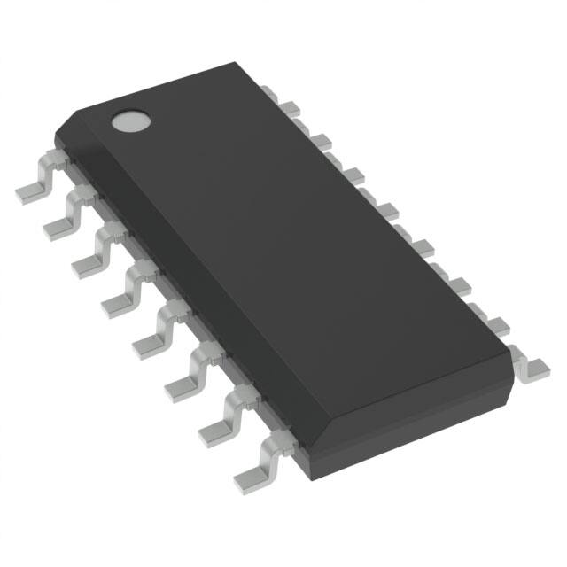
The L2720D is a monolithic integrated circuits in SO16 package, intended for use as power operational
amplifiers in a wide range of applications including
servo amplifiers and power supplies.
SO-16 (narrow)
ORDERING NUMBER: L2720D
It is particularly indicated for driving, inductive loads,
as motor and finds applications in compact-disc VCR
automotive, etc.
The high gain and high output power capability provide superior performance whatever an operational
amplifier/power booster combination is required.
BLOCK DIAGRAM
September 2002
1/6
�L2720D
PIN CONNECTION (Top view)
)
s
(
t
c
u
d
o
)
r
s
(
P
t
c
e
t
u
e
d
l
o
o
r
s
P
b
e
O
t
e
l
)
o
s
(
s
t
b
c
u
O
d
o
)
r
s
P
(
t
c
e
t
u
e
l
d
o
o
r
s
P
b
O
e
t
e
l
o
s
b
O
SCHEMATIC DIAGRAM (one section)
ABSOLUTE MAXIMUM RATINGS
Symbol
Value
Unit
VS
Supply Voltage
28
V
VS
Peak Supply Voltage (50ms)
50
V
Vi
Input Voltage
Vs
Vi
Differential Input Voltage
±Vs
Io
DC Output Current
Ip
1
A
Peak Output Current (non repetitive)
1.5
A
Ptot
Power Dissipation at Tamb = 50°C
800
mW
Top
Operating Temperature
– 40 to 85
°C
Storage and Junction Temperature
– 40 to 150
°C
Tstg, Tj
2/6
Parameter
�L2720D
THERMAL DATA
Symbol
Parameter
Rth j-amb
Thermal Resistance Junction to ambient
Value
Unit
95
°C/W
Typ.
ELECTRICAL CHARACTERISTICS (Vs = 24V, Tamb = 25°C unless otherwise specified)
Symbol
Parameter
Vs
Single Supply Voltage
Vs
Split Supply Voltage
Is
Quiescent Drain Current
Test Conditions
Min.
Typ.
Max.
Unit
4
28
V
±2
± 14
V
V
V o = ---2
Vs = 24V
Vs = 8V
Input Bias Current
Ib
Input Offset Voltage
Ios
Input Offset Current
SR
Slew Rate
od
B
Gain-bandwidth Product
Ri
Input Resistance
Gv
O.L. Voltage Gain
f = 100Hz
f = 1kHz
eN
Input Noise Voltage
B = 22Hz to 22kHz
IN
Input Noise Voltage
CMR
Common Mode Rejection
SVR
Supply Voltage Rejection
VDROP(H) Drop voltage high
t
e
l
o
Cs
s
b
O
r
P
e
s
(
t
c
Vs = ±2.5V to ±12V
)
s
(
ct
Vs = ±2.5V to ±12V
f = 1KHz; Vs = 24V
RL = 10Ω; Vs = 6V
Gv = 30dB
Figure 1. Quiescent Current vs. Supply Voltage
500
mA
mA
1
µA
10
mV
100
nA
2
c
u
d
1.2
)
s
t(
ro
70
P
e
let
so
b
O
-
Thermal Shutdown Junction
Temperature
t
e
l
o
b
O
f = 100Hz; Vs = 24V
RG = 10kΩ; Vs = ±12V
VR = 0.5V; Vs = ±6V
u
d
o
Channel Separation
so
f = 1kHz
u
d
o
r
P
e
VDROP(L) Drop voltage low
)-
e
t
e
l
Pr
)
s
(
t
15
15
uc
0.2
Vos
Tsd
10
9
V/µs
MHz
kΩ
80
60
dB
10
µV
200
pA
66
84
dB
dB
60
70
75
80
Ip = 100mA
Ip = 500mA
0.7
1
1.5
V
Ip = 100mA
Ip = 500mA
0.3
0.5
1
V
60
60
dB
145
°C
Figure 2. Open Loop Gain vs. Frequency
s
b
O
3/6
�L2720D
Figure 3. Common Mode Rejection vs.
Frequency
Figure 6. Supply Voltage rejection vs.
Frequency
)
s
(
t
c
u
d
o
)
r
s
(
P
t
c
e
t
u
e
d
l
o
o
r
s
P
b
e
O
t
e
l
)
o
s
(
s
t
b
c
u
O
d
o
)
r
s
P
(
t
c
e
t
u
e
l
d
o
o
r
s
P
b
O
e
t
e
l
o
s
b
O
Figure 4. Output Swing vs. Load Current
(VS = ± 5V).
Figure 5. Output Swing vs. Load Current
(VS = ± 12V).
4/6
Figure 7. Channel Separation vs. Frequency
�L2720D
mm
DIM.
MIN.
TYP.
A
a1
inch
MAX.
MIN.
TYP.
1.75
0.1
0.25
a2
MAX.
0.069
0.004
0.009
1.6
0.063
b
0.35
0.46
0.014
0.018
b1
0.19
0.25
0.007
0.010
C
OUTLINE AND
MECHANICAL DATA
0.5
0.020
)
s
(
t
c
u
d
o
)
r
s
(
P
t
c
e
t
u
e
d
l
o
o SO16 Narrow
r
s
P
b
e
O
t
e
l
)
o
s
(
s
t
b
c
u
O
d
o
)
r
s
P
(
t
c
e
t
u
e
l
d
o
o
r
s
P
b
O
e
t
e
l
o
s
b
O
c1
45˚ (typ.)
D (1)
9.8
10
0.386
0.394
E
5.8
6.2
0.228
0.244
e
1.27
0.050
e3
8.89
0.350
F (1)
3.8
4
0.150
0.157
G
4.6
5.3
0.181
0.209
L
0.4
1.27
0.016
0.050
M
S
0.62
0.024
8˚(max.)
(1) D and F do not include mold flash or protrusions. Mold flash or potrusions shall not exceed 0.15mm (.006inch).
5/6
�L2720D
)
s
(
t
c
u
d
o
)
r
s
(
P
t
c
e
t
u
e
d
l
o
o
r
s
P
b
e
O
t
e
l
)
o
s
(
s
t
b
c
u
O
d
o
)
r
s
P
(
t
c
e
t
u
e
l
d
o
o
r
s
P
b
O
e
t
e
l
o
s
b
O
Information furnished is believed to be accurate and reliable. However, STMicroelectronics assumes no responsibility for the consequences
of use of such information nor for any infringement of patents or other rights of third parties which may result from its use. No license is granted
by implication or otherwise under any patent or patent rights of STMicroelectronics. Specifications mentioned in this publication are subject
to change without notice. This publication supersedes and replaces all information previously supplied. STMicroelectronics products are not
authorized for use as critical components in life support devices or systems without express written approval of STMicroelectronics.
The ST logo is a registered trademark of STMicroelectronics
2002 STMicroelectronics - All Rights Reserved
STMicroelectronics GROUP OF COMPANIES
Australia - Brazil - Canada - China - Finland - France - Germany - Hong Kong - India - Israel - Italy - Japan -Malaysia - Malta - Morocco Singapore - Spain - Sweden - Switzerland - United Kingdom - United States.
http://www.st.com
6/6
�
很抱歉,暂时无法提供与“L2720D13TR”相匹配的价格&库存,您可以联系我们找货
免费人工找货- 国内价格 香港价格
- 2500+6.638632500+0.85765
- 5000+6.488725000+0.83828
- 7500+6.413627500+0.82858
- 12500+6.3303912500+0.81783