®
L 2720/2/4
LOW DROP DUAL POWER OPERATIONAL AMPLIFIERS
. . . . . . . . .
OUTPUT CURRENT TO 1 A OPERATES AT LOW VOLTAGES SINGLE OR SPLIT SUPPLY LARGE COMMON-MODE AND DIFFERENTIAL MODE RANGE LOW INPUT OFFSET VOLTAGE GROUND COMPATIBLE INPUTS LOW SATURATION VOLTAGE THERMAL SHUTDOWN CLAMP DIODE
POWERDIP (8 + 8)
DESCRIPTION The L2720, L2722 and L2724 are monolithic integrated circuits in powerdip, minidip and SIP-9 packages, intended for use as power operational amplifiers in a wide range of applications including servo amplifiers and power supplies. They are particularly indicated for driving, inductive loads, as motor and finds applications in compactdisc VCR automotive, etc. The high gain and high output power capability provide superior performance whatever an operational amplifier/power booster combination is required. PIN CONNECTIONS ( top views)
MINIDIP (Plastic)
SIP9 ORDERING NUMBERS : L2720 (Powerdip) L2722 (Minidip) L2724 (SIP9)
L2720
L2722
L2724
July 2003
1/10
�L2720/2/4
B LOCK DIAGRAM L2720 L2722 L2724
SCHEMATIC DIAGRAM (one section)
ABSOLUTE MAXIMUM RATINGS
Symbol VS VS Vi Vi Io Ip Ptot Supply Voltage Peak Supply Voltage (50ms) Input Voltage Differential Input Voltage DC Output Current Peak Output Current (non repetitive) Power Dissipation at Tamb = 80 C (L2720), Tamb = 50 C (L2722) Tcase = 75oC (L2720) Tcase = 50oC (L2724) Storage and Junction Temperature
o o
Parameter
Value 28 50 Vs ±Vs 1 1.5 1 5 10 –40 to 150
Unit V V
A A W
o
Tstg, Tj 2/10
C
�L2720/2/4
THERMAL DATA
SIP-9 Rth j-case Rth j-amb Thermal Resistance Junction-case Thermal Resistance Junction-ambient Max. Max. 10oC/W 70oC/W Powerdip 15oC/W 70oC/W Minidip 70oC/W 100oC/W
ELECTRICAL CHARACTERISTICS Vs = 24V, Tamb = 25oC unless otherwise specified
Symbol Vs Vs Is Ib Vos Ios SR B Ri Gv eN IN CMR SVR Parameter Single Supply Voltage Split Supply Voltage Quiescent Drain Current Input Bias Current Input Offset Voltage Input Offset Current Slew Rate Gain-bandwidth Product Input Resistance O.L. Voltage Gain Input Noise Voltage Input Noise Voltage Common Mode Rejection Supply Voltage Rejection f = 100Hz f = 1kHz B = 22Hz to 22kHz f = 1kHz f = 100Hz RG = 10kΩ VR = 0.5V Vs = ±2.5V to ±12V Vs = ±2.5V to ±12V Channel Separation f = 1KHz RL = 10Ω Gv = 30dB Vs = 24V Vs = ±12V Vs = ±6V Ip = 100mA Ip = 500mA Ip = 100mA Ip = 500mA Vs = 24V Vs = 6V 66 60 500 70 80 60 10 200 84 70 75 80 0.7 1 0.3 0.5 60 60 1.5 V 1 dB
o
Test Conditions
Min. 4 ±2
Typ.
Max. 28 ± 14
Unit V V mA
Vs Vo = 2
Vs = 24V Vs = 8V
10 9 0.2
15 15 1 10 100 µA mV nA V/µs MHz kΩ dB µV pA dB dB
2 1.2
VDROP(HIGH) VDROP(LOW) Cs
V
Tsd
Thermal Shutdown Junction Temperature
C
145
Figure 1 :
Quiescent Current vs. Supply Voltage
FIgure 2 :
Open Loop Gain vs. Frequency
3/10
�L2720/2/4
Figure 3 : Common Mode Rejection vs. Frequency Figure 4 : Output Swing vs. Load Current (VS = ± 5 V.
Figure 5 :
Output Swing vs. Load Current (VS = ± 12 V.
Figure 6 :
Supply Voltage rejection vs. Frequency
Figure 7 :
Channel Separation vs. Frequency
4/10
�L2720/2/4
APPLICATION SUGGESTION In order to avoid possible instability occuring into final stage the usual suggestions for the linear power stages are useful, as for instance :
-
-
layout accuracy ; A 100nF capacitor connected between supply pins and ground ;
boucherot cell (0.1 to 0.2 µF + 1Ω series) between outputs and ground or across the load. With single supply operation, a resistor (1kΩ) between the output and supply pin can be necessary for stability.
Figure 8 :
Bidirectional DC Motor Control with µP Compatible Inputs
VS1 = logic supply voltage Must be VS2 > VS1 E1, E2 = logic inputs
Figure 9 :
Servocontrol for Compact-disc
Figure 10 : Capstan Motor Control in Video Recorders
Figure 11 : Motor Current Control Circuit
Note :
T he input voltage level is compatible with L291 (8 - BIT D/A converter)
5/10
�L2720/2/4
Figure 12 : Bidirectional Speed Control of DC Motors 2R3 . R1 For circuit stability ensure that RX > RM The voltage available at the terminals of the motor is VM = 2 (VI − and IM is the motor current. VS ) + |RO|. IM where |RO| = 2 RX 2R3 . R1 where RM = internal resistance of motor.
Figure 13 : VHS-VCR Motor Control Circuit
6/10
�L2720/2/4
DIM. MIN. a1 B b b1 D E e e3 F I L Z 0.38 0.51 0.85
mm TYP. MAX. MIN. 0.020 1.40 0.50 0.50 20.0 8.80 2.54 17.78 7.10 5.10 3.30 1.27 0.015 0.033
inch TYP. MAX.
OUTLINE AND MECHANICAL DATA
0.055 0.020 0.020 0.787 0.346 0.100 0.700 0.280 0.201 0.130
Powerdip 16
0.050
7/10
�L2720/2/4
mm DIM. MIN. A a1 B b b1 D E e e3 e4 F I L Z 3.18 7.95 2.54 7.62 7.62 6.6 5.08 3.81 1.52 0.125 0.51 1.15 0.356 0.204 1.65 0.55 0.304 10.92 9.75 0.313 0.100 0.300 0.300 0.260 0.200 0.150 0.060 TYP. 3.32 0.020 0.045 0.014 0.008 0.065 0.022 0.012 0.430 0.384 MAX. MIN. TYP. 0.131 MAX. inch
OUTLINE AND MECHANICAL DATA
Minidip
8/10
�L2720/2/4
mm MIN. A a1 B B3 b1 b3 C c1 c2 D d1 e e3 L L1 L2 L3 L4 M N P 17.4 3.2 1 0.15 3.1 3 17.6 0.25 17.85 0.685 0.126 0.039 0.006 14.5 2.54 20.32 0.122 0.118 0.693 0.010 0,702 0.85 3.3 0.43 1.32 21.2 0.571 0.100 0.800 0.5 1.6 0.033 0.130 0.017 0.052 0.835 2.7 TYP. MAX. 7.1 3 23 24.8 0.020 0.063 0.106 MIN. inch TYP. MAX. 0.280 0.118 0.90 0.976
DIM.
OUTLINE AND MECHANICAL DATA
SIP9
D
C
L1
N P
M
L3
c2
d1
L4
L2
a1
1
9
L
b1 b3 e3 B B3
SIP9
e
c 1
A
9/10
�L2720/2/4
Information furnished is believed to be accurate and reliable. However, STMicroelectronics assumes no responsibility for the consequences of use of such information nor for any infringement of patents or other rights of third parties which may result from its use. No license is granted by implication or otherwise under any patent or patent rights of STMicroelectronics. Specification mentioned in this publication are subject to change without notice. This publication supersedes and replaces all information previously supplied. STMicroelectronics products are not authorized for use as critical components in life support devices or systems without express written approval of STMicroelectronics. The ST logo is a registered trademark of STMicroelectronics © 2003 STMicroelectronics – Printed in Italy – All Rights Reserved STMicroelectronics GROUP OF COMPANIES Australia - Brazil - Canada - China - Finland - France - Germany - Hong Kong - India - Israel - Italy - Japan - Malaysia - Malta - Morocco Singapore - Spain - Sweden - Switzerland - United Kingdom - United States. http://www.st.com
10/10
�
很抱歉,暂时无法提供与“L2722”相匹配的价格&库存,您可以联系我们找货
免费人工找货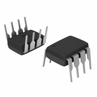


 工商网监
湘ICP备2023018690号
工商网监
湘ICP备2023018690号

