L6234
Three-phase motor driver
Datasheet - production data
Description
The L6234 is a triple half bridge to drive a
brushless DC motor.
It is realized in BCDmultipower technology which
combines isolated DMOS power transistors with
CMOS and bipolar circuits on the same chip.
1PXFS40��
By using mixed technology it has been possible to
optimize the logic circuitry and the power stage to
achieve the best possible performance.
Features
The output DMOS transistors can sustain a very
high current due to the fact that the DMOS
structure is not affected by the second breakdown
effect, the RMS maximum current is practically
limited by the dissipation capability of the
package.
Supply voltage from 7 to 52 V
5 A peak current
RDSon 0.3 typ. value at 25 °C
Cross conduction protection
TTL compatible driver
All the logic inputs are TTL, CMOS and µP
compatible. Each channel is controlled by two
separate logic inputs.
Operating frequency up to 150 kHz
Thermal shutdown
Intrinsic fast free wheeling diodes
Input and enable function for each half bridge
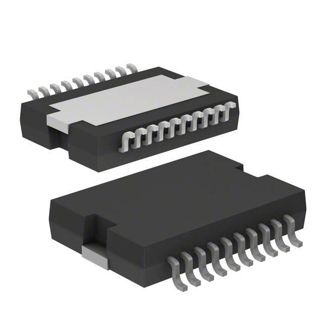
The L6234 device is available in a 20-pin
PowerSO20 package.
Table 1. Device summary
10 V external reference available
March 2017
This is information on a product in full production.
Order code
Package
Packing
L6234PD
PowerSO20
Tube
L6234PD013TR
PowerSO20
Tape and reel
DocID1107 Rev 11
1/15
www.st.com
�Contents
L6234
Contents
1
Block diagram . . . . . . . . . . . . . . . . . . . . . . . . . . . . . . . . . . . . . . . . . . . . . . 3
2
Pin connections . . . . . . . . . . . . . . . . . . . . . . . . . . . . . . . . . . . . . . . . . . . . . 4
3
Thermal data . . . . . . . . . . . . . . . . . . . . . . . . . . . . . . . . . . . . . . . . . . . . . . . 5
4
Maximum ratings . . . . . . . . . . . . . . . . . . . . . . . . . . . . . . . . . . . . . . . . . . . . 6
Recommended operating conditions . . . . . . . . . . . . . . . . . . . . . . . . . . . . . . . . . . . 6
5
Electrical characteristics . . . . . . . . . . . . . . . . . . . . . . . . . . . . . . . . . . . . . 7
6
Circuit description . . . . . . . . . . . . . . . . . . . . . . . . . . . . . . . . . . . . . . . . . . . 8
7
Typical characteristics . . . . . . . . . . . . . . . . . . . . . . . . . . . . . . . . . . . . . . . 9
8
Package information . . . . . . . . . . . . . . . . . . . . . . . . . . . . . . . . . . . . . . . . 12
8.1
9
2/15
PowerSO20 package information . . . . . . . . . . . . . . . . . . . . . . . . . . . . . . . 12
Revision history . . . . . . . . . . . . . . . . . . . . . . . . . . . . . . . . . . . . . . . . . . . 14
DocID1107 Rev 11
�L6234
1
Block diagram
Block diagram
Figure 1. Block diagram
".�����W�
DocID1107 Rev 11
3/15
15
�Pin connections
2
L6234
Pin connections
Figure 2. Pin connections
Table 2. Pin functions
4/15
Pin no.
Name
Function
1, 10
11, 20
GND
Common ground terminal. In the PowerSO package these pins are used to
dissipate the heat forward the PCB.
2
SENSE1
A sense resistor connected to this pin provides feedback for motor current
control for the bridges 1 and 2.
3
8
13
EN 2
EN 1
EN 3
Enable of the channels 1/2/3. A logic LOW level on this pin switches off both
power DMOS of the related channel.
4
7
14
IN 2
IN 1
IN 3
Logic input of channels 1/2/3. A logic HIGH level (when the corresponding EN
pin is HIGH) switches ON the upper DMOS power transistor, while a logic
LOW switches ON the corresponding low side power DMOS.
5
6
15
OUT 2
OUT 1
OUT 3
9, 12
Vs
16
VREF
17
VCP
18
VBOOT
Overvoltage input to drive the upper DMOS
19
SENSE2
A sense resistor connected to this pin provides feedback for motor current
control for the bridge 3.
Output of the channels 1/2/3.
Power supply voltage.
Internal voltage reference. A capacitor connected from this pin to GND
increases the stability of the power DMOS drive circuit.
Bootstrap oscillator. Oscillator output for the external charge pump.
DocID1107 Rev 11
�L6234
3
Thermal data
Thermal data
Table 3. Thermal data
Symbol
Rth j-case
Parameter
Thermal resistance junction case
DocID1107 Rev 11
PowerSO20
Unit
1.5
°C/W
5/15
15
�Maximum ratings
4
L6234
Maximum ratings
Table 4. Absolute maximum ratings
Symbol
Parameter
VS
Power supply voltage
VIN, VEN
Input enable voltage
Ipeak
VSENSE
Pulsed output current
(1)
Sensing voltage (DC voltage)
Value
Unit
52
V
– 0.3 to 7
V
5
A
-1 to 4
V
Vboot
Bootstrap peak voltage
62
V
VOD
Differential output voltage (between any of the 3 OUT pins)
60
V
Commutation frequency
150
kHz
Reference voltage
12
V
Total power dissipation (TA = 70 °C )
2.3
W
-40 to 150
°C
Value
Unit
7 to 42
V
fC
VREF
Ptot
Tstg, Tj
Storage and junction temperature range
1. Pulse width limited only by junction temperature and the transient thermal impedance.
Recommended operating conditions
Table 5. Recommended operating conditions
Symbol
VS
Supply voltage
VOD
Peak to peak differential voltage (between any of the 3 out pins)
52
V
Iout
DC output current (TA = 25 °C)
4
A
Sensing voltage (pulsed tw < 300 nsec)
-4 to 4
V
Sensing voltage (DC)
-1 to 1
V
-40 to 125
°C
VSENSE
Tj
6/15
Parameter
Junction temperature range
DocID1107 Rev 11
�L6234
5
Electrical characteristics
Electrical characteristics
VS = 42 V; Tj = 25 °C unless otherwise specified.
Table 6. Electrical characteristics
Symbol
Parameter
Test condition
Min.
Typ.
Max.
Unit
VS
Supply voltage
-
7
-
52
V
Vref
Reference voltage
-
-
10
-
V
IS
Quiescent supply current
-
-
6.5
-
mA
TS
Thermal shutdown
-
150
-
-
°C
TD
Dead time protection
-
-
300
-
ns
Leakage current
-
-
-
1
mA
ON resistance
-
-
0.3
-
Ω
Output DMOS transistor
IDSS
RDSon
Source drain diode
VSD
Forward ON voltage
ISD = 4 A; EN = LOW
-
1.2
-
V
TRR
Reverse recovery time
IF = 4 A
-
900
-
ns
Tpr
Forward recovery time
-
-
200
-
ns
VINL, VENL Input LOW voltage
-
-0.3
-
0.8
V
VINH, VENH Input HIGH voltage
-
2
-
7
V
-10
µA
-
µA
Logic levels
IINL, IENL
Input LOW current
VIN, VEN = L
-
IINH, IENH
Input HIGH current
VIN, VEN = H
-
DocID1107 Rev 11
30
7/15
15
�Circuit description
6
L6234
Circuit description
The L6234 is a triple half bridge designed to drive brushless DC motors. Each half bridge
has 2 power DMOS transistors with RDSon = 0.3 .
The 3 half bridges can be controlled independently by means of the 3 inputs IN1, IN2, IN3
and the 3 inputs EN1, EN2, and EN3. An external connection to the 3 common low side
DMOS sources is provided to connect a sensing resistor for the constant current chopping
application.
The driving stage and the logic stage are designed to work from 7 V to 52 V.
8/15
DocID1107 Rev 11
�L6234
Typical characteristics
7
Typical characteristics
Figure 3. Quiescent current vs. supply voltage
Figure 4. Normalized quiescent current vs.
switching frequency
,T �> P $ @
,T��,T# ��� +]�
��
����
�
7M� ����&
7 M� ���� &
7M� ���&
�
7 M� ��� &
�
�
���
7M� ���� &
7 M� �� �� &
����
�
7 M� �� �� &
�
�
�
�
�
�
����
�
�
��
��
9 V >9 @
��
��
�
��
��
��
��
IVZ >N+]@
��
��
$0�����Y�
Figure 5. Typical RDSon vs. supply voltage
��
$0�����Y�
Figure 6. Source drain forward on voltage vs.
junction temperature
96 ' �>9@
5 ' 6 ��2 1 �
> : �@ � � � �
�
����
� ��
7 M� � � �� � &
���
� ��
����
� ��
�
7 M� � � �� &
� ��
����
7 M ��� &
� ��
���
,RXW �$
� ��
�
,R X W
�
�
����
�� �$
��
��
��
9 V �>9 @
��
��
�
���
$0�����Y�
DocID1107 Rev 11
���
�
��
��
7M�>& @
��
�� �
�� �
�� �
$0�����Y�
9/15
15
�Typical characteristics
L6234
Figure 7. Typical diode forward ON
characteristics
Figure 8. Reference voltage vs. supply voltage
,6 ' �> $ @
9UHI�>9 @
�
��
7 M� ��� &
��
�
' 0 2 6 ��2 1 �
' 0 2 6 �2 ))�
�
�
�
�
�
7 M� �� �&
�
�
�
�
�
���
�
9 6 ' >9 @
���
�
�
$0�����Y�
Figure 9. Reference voltage vs. junction
temperature
��
��
��
9 V >9 @
��
��
$0�����Y�
Figure 10. PowerSO20 transient thermal
resistance
9 UH I�> 9 @
��
9 V � �� �9
��
9 V � �� �9
�
�
9 V � �� �9
�
�
9 V � �� 9
�
�
�
�
�
�
���
���
�
��
��
7 M > & @
��
� ��
� ��
� ��
$0�����Y�
10/15
DocID1107 Rev 11
$0�����Y�
�L6234
Typical characteristics
Figure 11. PowerSO20 thermal resistance
(mounted on aluminium substrate)
Figure 12. PowerSO20 thermal resistance
(mounted on FR4 monolayer substrate)
$0�����Y�
Figure 13. PowerSO20: with external heatsink
$0�����Y�
Figure 14. Thermal impedance of PowerSO20
and standard SO20
$0�����Y�
DocID1107 Rev 11
$0�����Y�
11/15
15
�Package information
8
L6234
Package information
In order to meet environmental requirements, ST offers these devices in different grades of
ECOPACK® packages, depending on their level of environmental compliance. ECOPACK®
specifications, grade definitions and product status are available at: www.st.com.
ECOPACK® is an ST trademark.
8.1
PowerSO20 package information
Figure 15. PowerSO20 package outline
1
5
1
D�
E
$
H
'(7$,/�$�
F
D�
'(7$,/�%�
(
H�
+
'(7$,/�$�
OHDG
'
VOXJ
D�
'(7$,/�%�
��
��
����
*DJH�3ODQH�
��&��
6
6($7,1*�3/$1(�
/
*
(�
(�
%27720�9,(:�
&
�&23/$1$5,7<�
7
(�
�
K�[����
��
362��0(&
'�
�������
12/15
DocID1107 Rev 11
�L6234
Package information
Table 7. PowerSO20 package mechanical data
Dimensions (mm )
Symbol
Min.
Typ.
Max.
A
-
-
3.6
a1
0.1
-
0.3
a2
-
-
3.3
a3
0
-
0.1
b
0.4
-
0.53
c
0.23
-
0.32
D(1)
15.8
-
16
D1
9.4
-
9.8
E
13.9
-
14.5
e
-
1.27
-
e3
-
11.43
-
10.9
-
11.1
E2
-
-
2.9
E3
5.8
-
6.2
G
0
-
0.1
H
15.5
-
15.9
h
-
-
1.1
L
0.8
-
1.1
(1)
E1
N
8° (typ.)
S
8° (max.)
T
-
10
-
1. “D” and “E1” do not include mold flash or protrusions.
- Mold flash or protrusions shall not exceed 0.15 mm (0.006").
DocID1107 Rev 11
13/15
15
�Revision history
9
L6234
Revision history
Table 8. Document revision history
Date
Revision
15-Nov-2011
10
Updated Features in coverpage and Table 4.
11
Removed PowerDIP 20-pin package and all references throughout
document.
Updated Figure 1 on page 3 (replaced by new figure).
Added note 1. below Table 7 on page 13.
Minor modifications throughout document.
15-Mar-2017
14/15
Changes
DocID1107 Rev 11
�L6234
IMPORTANT NOTICE – PLEASE READ CAREFULLY
STMicroelectronics NV and its subsidiaries (“ST”) reserve the right to make changes, corrections, enhancements, modifications, and
improvements to ST products and/or to this document at any time without notice. Purchasers should obtain the latest relevant information on
ST products before placing orders. ST products are sold pursuant to ST’s terms and conditions of sale in place at the time of order
acknowledgement.
Purchasers are solely responsible for the choice, selection, and use of ST products and ST assumes no liability for application assistance or
the design of Purchasers’ products.
No license, express or implied, to any intellectual property right is granted by ST herein.
Resale of ST products with provisions different from the information set forth herein shall void any warranty granted by ST for such product.
ST and the ST logo are trademarks of ST. All other product or service names are the property of their respective owners.
Information in this document supersedes and replaces information previously supplied in any prior versions of this document.
© 2017 STMicroelectronics – All rights reserved
DocID1107 Rev 11
15/15
15
�
很抱歉,暂时无法提供与“L6234PD013TR”相匹配的价格&库存,您可以联系我们找货
免费人工找货- 国内价格
- 600+51.98484
- 3000+50.94554
- 国内价格 香港价格
- 1+61.687431+7.97669
- 10+47.4922410+6.14114
- 25+43.9332125+5.68093
- 100+40.02246100+5.17523
- 250+38.73566250+5.00884