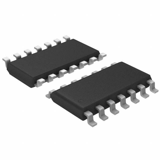
L9669
FAULT TOLERANT CAN TRANSCEIVER
■
■
■
■
■
■
■
■
FAULT TOLERANT DIFFERENTIAL
CAN TRANSCEIVER
OPERATING SUPPLY VOLTAGE 6V TO 28V,
TRANSIENTS UP TO 40V
LOW QUIESCENT CURRENT IN STANDBY
MODE (100µA) AND SLEEP MODE (37µA)
ON CHIP DIAGNOSIS FOR ERRORS ON THE
PHYSICAL BUSLINES WITH MICRO
CONTROLLER INTERFACE
OPTIMIZED EMI BEHAVIOUR DUE TO LIMITED
AND SYMMETRIC SLOPES OF CAN SIGNALS
AUTOMATIC SWITCHING TO SINGLE WIRE
MODE UPON BUS FAILURES
TWO-EDGE SENSITIVE WAKE-UP PIN
SUPPORTS TRANSMISSION WITH GROUND
SHIFT VOLTAGES ACCORDING TO GIFT
SPECIFICATION:
– SINGLE WIRE: 1.5V
Figure 1. Block Diagram
KL30
(+12V)
SO14
ORDERING NUMBER: L9669
■
– DIFFERENTIAL WIRE: 3V
AN UNPOWERED NODE OR UNSUFFICIENT
SUPPLIES DO NOT DISTURB THE BUS
LINES
c
u
d
DESCRIPTION
)
s
t(
o
r
P
The L9669 is an integrated circuit which contains a
CAN physical line interface. It integrates all main local functions for automotive body electronic applications connected to a CAN bus.
e
t
le
o
s
b
O
-
Voltage +5V
Regulator
)
s
(
ct
VS
14
5Vint
u
d
o
75k
WAKE
7
r
P
e
VCC
Wake-up
Control
VCC
10
INH
1
CANH
Driver
11 CANH
12.5k
t
e
l
o
TXD
2
CANH
Driver
s
b
O
Filter
Receiver
NSTB
EN
6
Low
Power
Control
Error
Management
& Diagnosis
R RTH
3
CANH Termination
5
CANL Termination
R RTL
RXD
8 RTH
9 RTL
4
100k
CAN
BUSLINE
12 CANL
TXD
Control
NERR
100k
13
GND
99AT0001
December 2003
1/14
�L9669
Figure 2. Pin Connection top view.
INH
1
14
VS
TXD
2
13
GND
RXD
3
12
CANL
NERR
4
11
CANH
NSTB
5
10
VCC
EN
6
9
RTL
WAKE
7
8
RTH
99AT0002
Table 1. Pin Functions
Pin
1
INH
Inhibit Output - for switching external 5V Regulator
2
TXD
Transmit Data Input - active LOW dominant Bit transmission
3
RXD
Receive Data Output - active LOW dominant Bit reception
4
NERR
Error/Diagnostic Output - active LOW error/Wake-up and Diagnostic output
5
NSTB
Not Standby Input - Digital control signal for low power modes
6
EN
7
WAKE
8
RTH
Termination Resistor for CANH - controlled by internal error management
9
RTL
Termination Resistor for CANL - controlled by internal error management
10
VCC
11
CANH
High Voltage Bus Line - High: dominant state
CANL
Low Voltage Bus Line - Low: dominant state
GND
Ground
bs
13
Function
14
VS
e
t
le
o
r
P
o
s
b
O
-
Enable Input/Diagnostic Clock Digital control signal for low power modes/Diagnostic clock
)
s
(
ct
Wake-Up Input - If level of VWAKE changes the device initiates a wake-up from sleep mode by
switching INH to VS
u
d
o
r
P
e
t
e
l
o
12
O
c
u
d
N°
)
s
t(
Supply Voltage Input - +5V
Battery Voltage Input - +12V
Table 2. Thermal Data
Symbol
Rthj-amb
2/14
Parameter
Thermal resistance junction to ambient
Value
Unit
120
°C/W
�L9669
Table 3. Absolute Maximum Ratings
For externally applied voltages or currents exceeding these limits damage of the circuit may occur!
Symbol
Parameter
Value
Unit
DC operating battery voltage
-0.3 to +28
V
VS-P
Pulse operating battery voltage (t
很抱歉,暂时无法提供与“L9669013TR”相匹配的价格&库存,您可以联系我们找货
免费人工找货