P-NUCLEO-6180X2
Proximity, gesture, ambient light sensor expansion board based on
VL6180X for STM32L053R8
Data brief
integrate the VL6180X in customer’s
application.
• Basic gesture recognition application can be
developed using the VL6180X sensor on the
expansion board and/or up to three sensors on
the satellite boards.
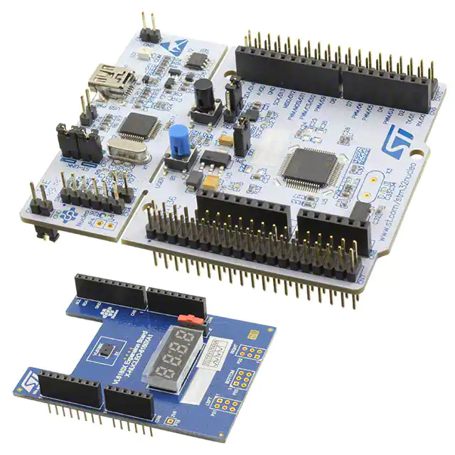
Description
The P-NUCLEO-6180X2 is an evaluation pack
that provides an introduction to the proximity,
ranging and light sensing capabilities of the
VL6180X sensor, combined with the ultra low
power STM32L053R8 microcontroller.
Features
• 1x VL6180X (proximity, gesture and ambient
light sensing module) expansion board.
– Slider switch controlling 2 functions:
- Ranging measurement.
- Ambient light sensing, up to 100KLux.(a)
– 4-digit display, displaying either the
distance of a target from the proximity
sensor or the lux value from the ambient
light sensing (ALS).
– Excellent ranging accuracy, independent of
the reflectance of the target.
• 1x NUCLEO-L053R8 board
• Power management access point
• Equipped with Arduino UNO R3 connector.
• RoHS compliant.
The VL6180X is the latest product based on ST’s
patented FlightSenseTM technology. This is a
ground-breaking technology allowing absolute
distance to be measured independent of target
reflectance. Instead of estimating the distance by
measuring the amount of light reflected back from
the object (which is significantly influenced by
color and surface), the VL6180X precisely
measures the time the light takes to travel to the
nearest object and reflect back to the sensor
(Time-of-Flight).
The STM32 Nucleo board, NUCLEO-L053R8,
provides an affordable and flexible way for users
to try out new ideas and build prototypes with any
STM32 microcontroller line, choosing from the
various combinations of performance, power
consumption and features.
• Full system SW supplied, download from
www.st.com/vl6180x in the folder “Design
resources”.
• 3x VL6180X satellite boards can be connected
on the VL6180X expansion board, in order to
a. VL6180X detects up to 100KLux but since the display
is 4 digits only, maximum displayed value is limited to
9999 Lux
June 2015
DocID027625 Rev 3
For further information contact your local STMicroelectronics sales office.
1/8
www.st.com
�Ordering information
P-NUCLEO-6180X2
Ordering information
Table 1. Ordering code
Order code
Description
P-NUCLEO-6180X2
VL6180X expansion board and NUCLEO-L053R8
board
VL6180X-SATEL
Optional board: VL6180X satellite board
NUCLEO-L053R8 board
Information about NUCLEO-L053R8 board can be found at
http://www.st.com/stm32nucleo.
VL6180X expansion board
The board allows the user to test the VL6180X functionality, to program it and to help
understanding how to develop an application using VL6180X. It integrates:
•
a 4-Digit display to render either the range value in mm or the ambient light value in
Lux.
•
a switch to select the value type to be displayed.
•
a 2.8V regulator to supply the VL6180X.
•
two level shifters to adapt the I/O level to the micro controller main board.
•
the necessary connectivity for the application.
It is required to program the NUCLEO-L053R8 board in order to control the VL6180X
expansion board. For the NUCLEO-L053R8 board, the required software suite is available
on www.st.com, on the P-NUCLEO-6180X2 page, and is composed of
STSW-LINK008, STSW-LINK7 and the X-CUBE-6180XA1.
The VL6180X expansion board and the NUCLEO-L053R8 board are connected through
Arduino compatible connectors CN5, CN6, CN8 and CN9 as shown in Figure 1 and
described in Table 2 and Table 3.
The Arduino connectors on NUCLEO-L053R8 board support Arduino Uno Revision 3.
2/8
DocID027625 Rev 3
�P-NUCLEO-6180X2
VL6180X expansion board
Figure 1. Arduino Uno connector layout
&1�
6&/
��
'��
6'$
�
'��
�
$9''
�
*1'
&1�
1&
�
,25()
�
5(6(7
�
����9
�
��9
,17B/
9,2
�
� 5��
*3,2�B/
�
�
�9�
�
�
�
*1'
�
1& 5��
*1'
,17B/
�
�
9,1
$�
�
$�
�
$�
$�
$�
$�
�
�
1& 5��
,17B5
'�
�
,17B%
5�� 1&
�
�
,17
5�� 1&
�
,17B5
&1�
'�
�
,17
� 5��
'�
'�
�
*3,2�B5
'��
'�
'�
�
*3,2�
'��
�
�
5�� �
'��
�
,17B% 5�� �
*3,2�B%
'��
�
'�
'�
'�
'�
&1�
Table 2. Arduino Uno left connector on NUCLEO-L053R8 board
CN Nb
VL6180X
board
VL6180X expansion board
function
Pin Nb
Pin name
1
NC
2
VIO
3
NC
4
+3V3
5
NC
Gnd
6
Gnd
Gnd
Gnd
Gnd
7
Gnd
Gnd
Gnd
8
NC
VIO
Power
MCU pin
Level shifter reference (3.3V)
3.3V supply
CN6 Power
DocID027625 Rev 3
-
3/8
8
�VL6180X expansion board
P-NUCLEO-6180X2
Table 2. Arduino Uno left connector on NUCLEO-L053R8 board (continued)
VL6180X
board
CN Nb
CN8 Analog
MCU pin
VL6180X expansion board
function
INT_B
PA4
Interrupt signal from VL6180X
bottom satellite plug-in
4
INT
PB0
Interrupt signal from VL6180X
on board soldered device
GPIO1_B
5
INT_B*
PC1 or PB9(1)
Interrupt signal from VL6180X
bottom satellite plug-in
GPIO1
6
INT*
PC1 or PB8(1)
Interrupt signal from VL6180X
on board soldered device
Pin Nb
Pin name
1
NC
2
NC
GPIO1_B
3
GPIO1
1. Depending on Nucleo board solder bridges, see details on Nucleo documentation. These interrupt signals
are duplicated, but not used, this offers hardware connection flexibility in case of conflict on MCU interface
management when expansion board is used superposed with other expansion boards, in this case
remove 0 ohm resistor from interrupt used and connect 0 ohm resistor in place of “do not mount” one.
Table 3. Arduino Uno right connector on NUCLEO-L053R8 board
CN Nb
VL6180X
expansion
board
Pin Nb Pin name MCU pin
VL6180X expansion board function
SCL
10
D15
PB8
I2C1_SCL
SDA
9
D14
PB9
I2C1_SDA
8
NC
Gnd
7
Gnd
Gnd
Gnd
GPIO1_L
6
INT_L
PA5
Interrupt signal from VL6180X left
satellite plug-in
5
NC
4
NC
3
NC
2
NC
1
INT_L*
PA9
Interrupt signal from VL6180X left
satellite plug-in(1)
CN5 Digital
GPIO1_L
4/8
DocID027625 Rev 3
�P-NUCLEO-6180X2
Optional VL6180X satellite board
Table 3. Arduino Uno right connector on NUCLEO-L053R8 board (continued)
VL6180X
expansion
board
CN Nb
GPIO1_R
Pin Nb Pin name MCU pin
8
NC
7
NC
6
NC
5
INT_R*
4
NC
3
INT_R
2
NC
1
NC
VL6180X expansion board function
PB5
Interrupt signal from VL6180X right
satellite plug-in(1)
PA10
Interrupt signal from VL6180X right
satellite plug-in
CN9 Digital
GPIO1_R
1. These interrupt signals are duplicated, but not used, this offers hardware connection flexibility in case of
conflict on MCU interface management when expansion board is used superposed with other expansion
boards, in this case remove 0 ohm resistor from interrupt used and connect 0 ohm resistor in place of “do
not mount” one.
Optional VL6180X satellite board
The VL6180X expansion board allows connecting up to 3x VL6180X satellite boards (see
Figure 2). This allows to develop applications controlling up to 4x VL6180X.
•
I2C bus is common with the VL6180X on-board: I2C bus,
•
each satellite can be connected through a dedicated connector to be soldered on the
expansion board and has its own:
–
interrupt (GPIO1-x) pin, routed from each satellite connector to the Arduino
connectors.
–
reset (GPIO0-y) pin, routed from each satellite connector to the GPIO expander
device.
DocID027625 Rev 3
5/8
8
�Optional VL6180X satellite board
P-NUCLEO-6180X2
Figure 2. Connections of VL6180X satellite boards
Note:
VL6180X satellite boards can be ordered under the reference: VL6180X-SATEL.
Figure 3. VL6180X-SATEL
6/8
DocID027625 Rev 3
�P-NUCLEO-6180X2
Laser consideration
Laser consideration
The VL6180X contains a laser emitter and corresponding drive circuitry. The laser output is
designed to remain within Class 1 laser safety limits under all reasonably foreseeable
conditions including single faults in compliance with IEC 60825-1:2007. The laser output will
remain within Class 1 limits as long as the STMicroelectronics recommended device
settings are used and the operating conditions specified in the datasheet are respected. The
laser output power must not be increased by any means and no optics should be used with
the intention of focusing the laser beam.
Figure 4. Class 1 laser product label
Compliance
Complies with 21 CFR 1040.10 and 1040.11 except for deviations pursuant to Laser Notice
No.50, dated June 24, 2007.
ECOPACK®
In order to meet environmental requirements, ST offers these devices in different grades of
ECOPACK® packages, depending on their level of environmental compliance. ECOPACK®
specifications, grade definitions and product status are available at: www.st.com.
ECOPACK® is an ST trademark.
Revision history
Table 4. Document revision history
Date
Revision
Changes
19-Mar-2015
1
Initial release.
05-May-2015
2
Add ST cube logo on first page
02-Jun-2015
3
Update Description section
DocID027625 Rev 3
7/8
8
�P-NUCLEO-6180X2
IMPORTANT NOTICE – PLEASE READ CAREFULLY
STMicroelectronics NV and its subsidiaries (“ST”) reserve the right to make changes, corrections, enhancements, modifications, and
improvements to ST products and/or to this document at any time without notice. Purchasers should obtain the latest relevant information on
ST products before placing orders. ST products are sold pursuant to ST’s terms and conditions of sale in place at the time of order
acknowledgement.
Purchasers are solely responsible for the choice, selection, and use of ST products and ST assumes no liability for application assistance or
the design of Purchasers’ products.
No license, express or implied, to any intellectual property right is granted by ST herein.
Resale of ST products with provisions different from the information set forth herein shall void any warranty granted by ST for such product.
ST and the ST logo are trademarks of ST. All other product or service names are the property of their respective owners.
Information in this document supersedes and replaces information previously supplied in any prior versions of this document.
© 2015 STMicroelectronics – All rights reserved
8/8
DocID027625 Rev 3
�