PM8903A
3 A step-down monolithic switching regulator
Datasheet − production data
Features
■
Integrated 35 mΩ MOSFETs for high efficiency
■
3 A continuous output current
■
2.8 V to 6 V input voltage (VIN)
■
2.9 V to 5.5 V supply voltage (VCC)
■
Adjustable output voltage down to 0.6 V
■
1% output voltage accuracy
■
1.1 MHz switching frequency operation
■
PSKIP mode to optimize light load efficiency
■
Embedded bootstrap diode
■
Thermally compensated loss-less current
sense across HS and LS MOSFETs
■
OV/UV/OC and overtemperature protection
■
Internal soft-start and soft-stop
■
Interleaving synchronization (up to 2 ICs)
■
Power Good output
■
Shutdown function (< 15 µA quiescent current)
■
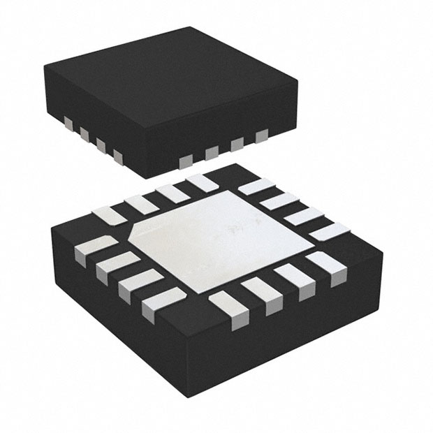
VFQFPN16 3 x 3 mm compact package
VFQFPN16 (3 x 3 mm)
The PM8903A features low-resistance integrated
nMOS and proprietary pulse-skipping mode for
optimum efficiency over all the loading range.
The voltage mode control loop allows the widest
range of output filters. Current sense is internally
thermally compensated for optimum precision.
Applications
■
Subsystem power supply
■
CPU, DSP and FPGA power supplies
■
Distributed power supply
■
General DC-DC converters
The integrated 0.6 V reference allows the
regulation of output voltages with ±1% accuracy
over temperature variations. Switching frequency
is typically set to 1.1 MHz and can be
programmed to 0.8 MHz or 1.0 MHz. Out of phase
synchronization allows the reduction of input RMS
current.
The PM8903A provides precise dual-threshold
overcurrent protection as well as
over/undervoltage and overtemperature
protection. PGOOD output easily provides realtime information on the output voltage.
Description
The PM8903A is a high efficiency monolithic stepdown switching regulator designed to deliver up to
3 A continuous current. The IC operates from 2.8
V to 6 V input voltage (VIN).
Table 1.
Device summary
The PM8903A is available in VFQFPN16 3 x 3
mm.
Order codes
Package
Packaging
PM8903A
VFQFPN16 (3 x 3 mm)
Tube
PM8903ATR
VFQFPN16 (3 x 3 mm)
Tape and reel
January 2013
This is information on a product in full production.
Doc ID 024147 Rev 1
1/33
www.st.com
33
�Contents
PM8903A
Contents
1
2
Typical application circuit and block diagram . . . . . . . . . . . . . . . . . . . . 3
1.1
Application circuit . . . . . . . . . . . . . . . . . . . . . . . . . . . . . . . . . . . . . . . . . . . . 3
1.2
Block diagram . . . . . . . . . . . . . . . . . . . . . . . . . . . . . . . . . . . . . . . . . . . . . . . 3
Pin description and connection diagrams . . . . . . . . . . . . . . . . . . . . . . . 4
2.1
Pin description . . . . . . . . . . . . . . . . . . . . . . . . . . . . . . . . . . . . . . . . . . . . . . 4
3
Thermal data . . . . . . . . . . . . . . . . . . . . . . . . . . . . . . . . . . . . . . . . . . . . . . . 6
4
Electrical specifications . . . . . . . . . . . . . . . . . . . . . . . . . . . . . . . . . . . . . . 7
5
4.1
Absolute maximum ratings . . . . . . . . . . . . . . . . . . . . . . . . . . . . . . . . . . . . . 7
4.2
Recommended operating conditions . . . . . . . . . . . . . . . . . . . . . . . . . . . . . 7
4.3
Electrical characteristics . . . . . . . . . . . . . . . . . . . . . . . . . . . . . . . . . . . . . . . 7
4.4
Typical operating characteristics . . . . . . . . . . . . . . . . . . . . . . . . . . . . . . . . 9
Device description . . . . . . . . . . . . . . . . . . . . . . . . . . . . . . . . . . . . . . . . . 12
5.1
Power section . . . . . . . . . . . . . . . . . . . . . . . . . . . . . . . . . . . . . . . . . . . . . . 12
5.2
Startup and shutdown management . . . . . . . . . . . . . . . . . . . . . . . . . . . . 13
5.3
6
Low-side-less startup . . . . . . . . . . . . . . . . . . . . . . . . . . . . . . . . . . . . . . . 14
5.2.2
Soft-off . . . . . . . . . . . . . . . . . . . . . . . . . . . . . . . . . . . . . . . . . . . . . . . . . . 14
Output voltage monitoring and protection . . . . . . . . . . . . . . . . . . . . . . . . 14
5.3.1
Overvoltage protection . . . . . . . . . . . . . . . . . . . . . . . . . . . . . . . . . . . . . . 14
5.3.2
Undervoltage protection . . . . . . . . . . . . . . . . . . . . . . . . . . . . . . . . . . . . . 15
5.3.3
Feedback disconnection protection . . . . . . . . . . . . . . . . . . . . . . . . . . . . 15
5.3.4
Power Good (PGOOD) . . . . . . . . . . . . . . . . . . . . . . . . . . . . . . . . . . . . . 15
5.4
Overcurrent protection . . . . . . . . . . . . . . . . . . . . . . . . . . . . . . . . . . . . . . . 16
5.5
Overtemperature protection . . . . . . . . . . . . . . . . . . . . . . . . . . . . . . . . . . . 16
5.6
Synchronization . . . . . . . . . . . . . . . . . . . . . . . . . . . . . . . . . . . . . . . . . . . . 16
5.7
Pulse-skipping . . . . . . . . . . . . . . . . . . . . . . . . . . . . . . . . . . . . . . . . . . . . . 17
5.8
Multifunction pin PSKIP/MS . . . . . . . . . . . . . . . . . . . . . . . . . . . . . . . . . . . 17
Application information . . . . . . . . . . . . . . . . . . . . . . . . . . . . . . . . . . . . . 18
6.1
2/33
5.2.1
Compensation network . . . . . . . . . . . . . . . . . . . . . . . . . . . . . . . . . . . . . . 18
Doc ID 024147 Rev 1
�PM8903A
7
Contents
6.2
Output voltage setting . . . . . . . . . . . . . . . . . . . . . . . . . . . . . . . . . . . . . . . 20
6.3
Inductor design . . . . . . . . . . . . . . . . . . . . . . . . . . . . . . . . . . . . . . . . . . . . . 21
6.4
Output capacitors . . . . . . . . . . . . . . . . . . . . . . . . . . . . . . . . . . . . . . . . . . . 21
6.5
Input capacitors . . . . . . . . . . . . . . . . . . . . . . . . . . . . . . . . . . . . . . . . . . . . 22
PM8903A demonstration board . . . . . . . . . . . . . . . . . . . . . . . . . . . . . . . 23
7.1
Detailed demonstration board description . . . . . . . . . . . . . . . . . . . . . . . . 24
7.1.1
Power input (VIN) . . . . . . . . . . . . . . . . . . . . . . . . . . . . . . . . . . . . . . . . . . 28
7.1.2
Signal input (VCC) . . . . . . . . . . . . . . . . . . . . . . . . . . . . . . . . . . . . . . . . . 28
7.1.3
Output (VOUT) . . . . . . . . . . . . . . . . . . . . . . . . . . . . . . . . . . . . . . . . . . . . 28
7.1.4
Test points and jumper connection . . . . . . . . . . . . . . . . . . . . . . . . . . . . 29
8
Package mechanical data . . . . . . . . . . . . . . . . . . . . . . . . . . . . . . . . . . . . 30
9
Revision history . . . . . . . . . . . . . . . . . . . . . . . . . . . . . . . . . . . . . . . . . . . 32
Doc ID 024147 Rev 1
3/33
�Typical application circuit and block diagram
1
Typical application circuit and block diagram
1.1
Application circuit
Figure 1.
1.2
Block diagram
Figure 2.
4/33
Typical application circuit
Block diagram
Doc ID 024147 Rev 1
PM8903A
�PM8903A
2
Pin description and connection diagrams
Pin description and connection diagrams
Pin connection (top view)
PGND
PGND
VIN
VIN
Figure 3.
16
15
14
13
1
12
2
11
3
10
4
9
5
6
7
8
VCC
GND
FB
COMP
PHASE
PHASE
PHASE
PSKIP / MS
EN
SYNCH
PGOOD
BOOT
2.1
Pin description
Table 2.
Pin description
Pin #
Name
Function
1
EN
Enable. Internally pulled up by 5 µA to VCC.
Force low to disable the device, set free or pull up above turn-on threshold to
enable the converter operations.
2
SYNCH
Synchronization pin.
According to PSKIP status, the IC sends the synchronization signal out of this
pin when master, while accepting a synchronization signal when slave.
Connect to the same SYNCH pin of a similar part when synchronizing ICs.
In case of single IC operation, leave floating.
3
PGOOD
Open drain output set free after SS has finished and pulled low when VOUT is
out of the PGOOD window or any protection is triggered.
Pull up to a voltage lower than VCC, if not used it can be left floating.
4
BOOT
Bootstrap pin.
It provides power supply for the floating high-side driver. Connect with 0.1 µF
to PHASE. See Figure 1.
5 to 7
PHASE
Output inductor connection.
The pins are connected to the embedded MOSFETs (high-side source and
low-side drain). Connect directly to output inductor. See Figure 1.
8
Pulse-skip and master/slave definition.
Connect with a resistor to GND or leave it floating to define:
Pulse-skip feature status;
PSKIP / MS
Master/slave for synchronization;
Switching frequency.
See Section 5.8 on page 17.
Doc ID 024147 Rev 1
5/33
�Pin description and connection diagrams
Table 2.
6/33
PM8903A
Pin description (continued)
Pin #
Name
Function
9
COMP
10
FB
11
GND
All the internal references are referred to this pin. Connect to the PCB Signal
Ground.
12
VCC
Device power supply.
Operative voltage is 2.9 V - 5.5 V. Filter with at least 1 µF MLCC vs. GND.
13, 14
VIN
Power input voltage, connected to embedded high-side drain.
Supply range is from 2.8 V to 6 V. Bypass VIN pins to PGND pins close to the
IC package with high quality MLCC capacitors (at least 10 µF). See Figure 1.
15, 16
PGND
Power ground connection, connected to embedded low-side MOSFET source.
Connect to PGND PCB plane. See Figure 1.
Thermal pad
Thermal pad connects the silicon substrate and makes good thermal contact
with the PCB. Connect to the PCB PGND plane.
Error amplifier output.
Connect with an (RF - CF) // CP to FB. See Figure 1
The device cannot be disabled by pulling low this pin.
Error amplifier inverting input.
Connect with RFB or RFB // (RS - CS) to VSEN and with an (RF - CF) // CP to
COMP. A resistor ROS to GND sets the output voltage ratio. See Figure 1
Doc ID 024147 Rev 1
�PM8903A
3
Thermal data
Thermal data
Table 3.
Symbol
Thermal data
Parameter
Value
Unit
RthJA
Thermal resistance junction-to-ambient
(Device soldered on standard demonstration board, see
Section 7 for details)
30
°C/W
RthJC
Thermal resistance junction-to-case
12
°C/W
TMAX
Maximum junction temperature
150
°C
TSTG
Storage temperature range
-40 to 150
°C
TJ
Junction temperature range
-25 to 125
°C
Doc ID 024147 Rev 1
7/33
�Electrical specifications
PM8903A
4
Electrical specifications
4.1
Absolute maximum ratings
Table 4.
Absolute maximum ratings
Symbol
Parameter
to PGND, GND
-0.3 to 6
V
VIN
to PGND, GND
-0.3 to 7
V
VBOOT
to PGND, GND
to PHASE
-0.3 to 13
-0.3 to 6
V
VPHASE
to PGND, GND
to PGND, GND, VIN=6 V, t
很抱歉,暂时无法提供与“PM8903A”相匹配的价格&库存,您可以联系我们找货
免费人工找货- 国内价格 香港价格
- 2000+9.405152000+1.21506