SPC584Gx, SPC58EGx,
SPC58NGx
32-bit Power Architecture microcontroller for automotive ASIL-D
applications
Datasheet - production data
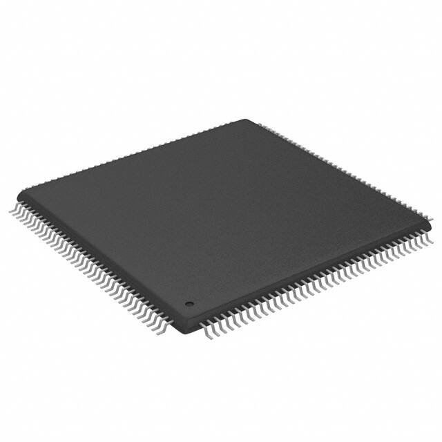
eTQFP144 (20 x 20 x 1.0 mm)
eLQFP176 (24 x 24 x 1.4 mm)
FPBGA292 (17 x 17 x 1.8 mm)
• Crossbar switch architecture for concurrent
access to peripherals, Flash, or RAM from
multiple bus masters with end-to-end ECC
Features
• AEC-Q100 qualified
• High performance e200z4 triple core:
– 32-bit Power Architecture technology CPU
– Core frequency as high as 180 MHz
– Variable Length Encoding (VLE)
– Floating Point, End-to-End Error Correction
• 6582 KB (6144 KB code flash+ 256 KB data
flash) on-chip flash memory:
– supports read during program and erase
operations, and multiple blocks allowing
EEPROM emulation
– Supports read while read between the two
code Flash partitions.
• 608 KB on-chip general-purpose SRAM (in
addition to 160 KB core local data RAM): 64KB
in CPU_0, 64 KB in CPU_1 and 32 KB in
CPU_2
• 182 KB HSM dedicated flash memory (144 KB
code + 32 KB data)
• Multi-channel direct memory access controller
(eDMA)
– one eDMA with 64 channels
– one eDMA with 32 channels
• 1 interrupt controller (INTC)
• Comprehensive new generation ASIL-D safety
concept:
– ASIL-D of ISO 26262
– One CPU channel in lockstep
July 2019
This is information on a product in full production.
– Logic BIST
– FCCU for collection and reaction to failure
notifications
– Memory BIST
– Cyclic redundancy check (CRC) unit
– Memory Error Management Unit (MEMU)
for collection and reporting of error events
in memories
• Body cross triggering unit (BCTU)
– Triggers ADC conversions from any eMIOS
channel
– Triggers ADC conversions from up to 2
dedicated PIT_RTIs
• Enhanced modular IO subsystem (eMIOS): up
to 64 timed IO channels with 16-bit counter
resolution
• Enhanced analog-to-digital converter system
with:
– 4 independent fast 12-bit SAR analog
converters
– One supervisor 12-bit SAR analog
converter
– One standby 10-bit SAR analog converter
• Communication interfaces:
– 18 LINFlexD modules
– 10 deserial serial peripheral interface
(DSPI) modules
– 8 MCAN interfaces with advanced shared
memory scheme and ISO CAN-FD support
– Dual-channel FlexRay controller
– Two independent Ethernet controllers
10/100Mbps compliant IEEE 802.3-2008
• Low power capabilities
– Versatile low power modes
– Ultra low power standby with RTC
– Smart Wake-up Unit for contact monitoring
DS11758 Rev 6
1/139
www.st.com
�SPC584Gx, SPC58EGx and SPC58NGx
– Fast wakeup schemes
• Dual phase-locked loops with stable clock domain for peripherals and FM modulation
domain for computational shell
• Nexus development interface (NDI) per IEEEISTO 5001-2003 standard, with some
support for 2010 standard
• Boot assist Flash (BAF) supports factory programming using a serial bootload through the
asynchronous CAN or LIN/UART
• Junction temperature range -40 °C to 150 °C
Table 1. Device summary
Part number
Package
4 MB
Single core
Dual core
6 MB
Triple core
Single core
Dual core
Triple core
eTQFP144 SPC584G80E5 SPC58EG80E5 SPC58NG80E5 SPC584G84E5 SPC58EG84E5 SPC58NG84E5
eLQFP176 SPC584G80E7 SPC58EG80E7 SPC58NG80E7 SPC584G84E7 SPC58EG84E7 SPC58NG84E7
FPBGA292 SPC584G80C3 SPC58EG80C3 SPC58NG80C3 SPC584G84C3 SPC58EG84C3 SPC58NG84C3
2/139
DS11758 Rev 6
�SPC584Gx, SPC58EGx, SPC58NGx
Table of contents
Table of contents
1
Introduction . . . . . . . . . . . . . . . . . . . . . . . . . . . . . . . . . . . . . . . . . . . . . . . . 6
2
Description . . . . . . . . . . . . . . . . . . . . . . . . . . . . . . . . . . . . . . . . . . . . . . . . . 7
2.1
Device feature summary . . . . . . . . . . . . . . . . . . . . . . . . . . . . . . . . . . . . . . 7
2.2
Block diagram . . . . . . . . . . . . . . . . . . . . . . . . . . . . . . . . . . . . . . . . . . . . . . 10
2.3
Features . . . . . . . . . . . . . . . . . . . . . . . . . . . . . . . . . . . . . . . . . . . . . . . . . . 12
3
Package pinouts and signal descriptions . . . . . . . . . . . . . . . . . . . . . . . 14
4
Electrical characteristics . . . . . . . . . . . . . . . . . . . . . . . . . . . . . . . . . . . . 15
4.1
Introduction . . . . . . . . . . . . . . . . . . . . . . . . . . . . . . . . . . . . . . . . . . . . . . . 15
4.2
Absolute maximum ratings . . . . . . . . . . . . . . . . . . . . . . . . . . . . . . . . . . . . 16
4.3
Operating conditions . . . . . . . . . . . . . . . . . . . . . . . . . . . . . . . . . . . . . . . . 19
4.3.1
Power domains and power up/down sequencing . . . . . . . . . . . . . . . . . 21
4.4
Electrostatic discharge (ESD) . . . . . . . . . . . . . . . . . . . . . . . . . . . . . . . . . 22
4.5
Electromagnetic compatibility characteristics . . . . . . . . . . . . . . . . . . . . . . 23
4.6
Temperature profile . . . . . . . . . . . . . . . . . . . . . . . . . . . . . . . . . . . . . . . . . 24
4.7
Device consumption . . . . . . . . . . . . . . . . . . . . . . . . . . . . . . . . . . . . . . . . . 25
4.8
I/O pad specification . . . . . . . . . . . . . . . . . . . . . . . . . . . . . . . . . . . . . . . . . 28
4.8.1
I/O input DC characteristics . . . . . . . . . . . . . . . . . . . . . . . . . . . . . . . . . . 28
4.8.2
I/O output DC characteristics . . . . . . . . . . . . . . . . . . . . . . . . . . . . . . . . . 31
4.8.3
I/O pad current specifications . . . . . . . . . . . . . . . . . . . . . . . . . . . . . . . . 36
4.9
Reset pad (PORST, ESR0) electrical characteristics . . . . . . . . . . . . . . . . 39
4.10
PLLs . . . . . . . . . . . . . . . . . . . . . . . . . . . . . . . . . . . . . . . . . . . . . . . . . . . . . 42
4.11
4.12
4.10.1
PLL0 . . . . . . . . . . . . . . . . . . . . . . . . . . . . . . . . . . . . . . . . . . . . . . . . . . . 42
4.10.2
PLL1 . . . . . . . . . . . . . . . . . . . . . . . . . . . . . . . . . . . . . . . . . . . . . . . . . . . 44
Oscillators . . . . . . . . . . . . . . . . . . . . . . . . . . . . . . . . . . . . . . . . . . . . . . . . . 45
4.11.1
Crystal oscillator 40 MHz . . . . . . . . . . . . . . . . . . . . . . . . . . . . . . . . . . . . 45
4.11.2
Crystal Oscillator 32 kHz . . . . . . . . . . . . . . . . . . . . . . . . . . . . . . . . . . . . 46
4.11.3
RC oscillator 16 MHz . . . . . . . . . . . . . . . . . . . . . . . . . . . . . . . . . . . . . . . 47
4.11.4
Low power RC oscillator . . . . . . . . . . . . . . . . . . . . . . . . . . . . . . . . . . . . 48
ADC system . . . . . . . . . . . . . . . . . . . . . . . . . . . . . . . . . . . . . . . . . . . . . . . 49
4.12.1
ADC input description . . . . . . . . . . . . . . . . . . . . . . . . . . . . . . . . . . . . . . 49
DS11758 Rev 6
3/139
5
�Table of contents
4.12.2
SAR ADC 12 bit electrical specification . . . . . . . . . . . . . . . . . . . . . . . . . 50
4.12.3
SAR ADC 10 bit electrical specification . . . . . . . . . . . . . . . . . . . . . . . . . 55
4.13
Temperature Sensor . . . . . . . . . . . . . . . . . . . . . . . . . . . . . . . . . . . . . . . . . 58
4.14
LFAST pad electrical characteristics . . . . . . . . . . . . . . . . . . . . . . . . . . . . 59
4.15
5
SPC584Gx, SPC58EGx, SPC58NGx
4.14.1
LFAST interface timing diagrams . . . . . . . . . . . . . . . . . . . . . . . . . . . . . . 59
4.14.2
LFAST and MSC/DSPILVDS interface electrical characteristics . . . . . . 60
4.14.3
LFAST PLL electrical characteristics . . . . . . . . . . . . . . . . . . . . . . . . . . . 63
Power management . . . . . . . . . . . . . . . . . . . . . . . . . . . . . . . . . . . . . . . . . 65
4.15.1
Power management integration . . . . . . . . . . . . . . . . . . . . . . . . . . . . . . . 65
4.15.2
Voltage regulators . . . . . . . . . . . . . . . . . . . . . . . . . . . . . . . . . . . . . . . . . 69
4.15.3
Voltage monitors . . . . . . . . . . . . . . . . . . . . . . . . . . . . . . . . . . . . . . . . . . 70
4.16
Flash memory . . . . . . . . . . . . . . . . . . . . . . . . . . . . . . . . . . . . . . . . . . . . . . 74
4.17
AC Specifications . . . . . . . . . . . . . . . . . . . . . . . . . . . . . . . . . . . . . . . . . . . 78
4.17.1
Debug and calibration interface timing . . . . . . . . . . . . . . . . . . . . . . . . . 78
4.17.2
DSPI timing with CMOS pads . . . . . . . . . . . . . . . . . . . . . . . . . . . . . . . . 84
4.17.3
Ethernet timing . . . . . . . . . . . . . . . . . . . . . . . . . . . . . . . . . . . . . . . . . . . . 94
4.17.4
FlexRay timing . . . . . . . . . . . . . . . . . . . . . . . . . . . . . . . . . . . . . . . . . . . 100
4.17.5
CAN timing . . . . . . . . . . . . . . . . . . . . . . . . . . . . . . . . . . . . . . . . . . . . . . 104
4.17.6
UART timing . . . . . . . . . . . . . . . . . . . . . . . . . . . . . . . . . . . . . . . . . . . . 104
4.17.7
I2C timing . . . . . . . . . . . . . . . . . . . . . . . . . . . . . . . . . . . . . . . . . . . . . . . 105
Package information . . . . . . . . . . . . . . . . . . . . . . . . . . . . . . . . . . . . . . . 107
5.1
eLQFP176 package information . . . . . . . . . . . . . . . . . . . . . . . . . . . . . . . 107
5.1.1
5.2
eTQFP144 package information . . . . . . . . . . . . . . . . . . . . . . . . . . . . . . .112
5.2.1
5.3
6
4/139
Package mechanical drawings and data information . . . . . . . . . . . . . 116
FPBGA292 package information . . . . . . . . . . . . . . . . . . . . . . . . . . . . . . .118
5.3.1
5.4
Package mechanical drawings and data information . . . . . . . . . . . . . 111
Package mechanical drawings and data information . . . . . . . . . . . . . 119
Package thermal characteristics . . . . . . . . . . . . . . . . . . . . . . . . . . . . . . 121
5.4.1
eTQFP144 . . . . . . . . . . . . . . . . . . . . . . . . . . . . . . . . . . . . . . . . . . . . . . 121
5.4.2
LQFP176 . . . . . . . . . . . . . . . . . . . . . . . . . . . . . . . . . . . . . . . . . . . . . . . 121
5.4.3
FPBGA292 . . . . . . . . . . . . . . . . . . . . . . . . . . . . . . . . . . . . . . . . . . . . . . 122
5.4.4
General notes for specifications at maximum junction temperature . . 122
Ordering information . . . . . . . . . . . . . . . . . . . . . . . . . . . . . . . . . . . . . . 125
DS11758 Rev 6
�SPC584Gx, SPC58EGx, SPC58NGx
7
Table of contents
Revision history . . . . . . . . . . . . . . . . . . . . . . . . . . . . . . . . . . . . . . . . . . 128
DS11758 Rev 6
5/139
5
�Introduction
1
SPC584Gx, SPC58EGx, SPC58NGx
Introduction
This document describes the features of the family and options available within the family
members, and highlights important electrical and physical characteristics of the device. To
ensure a complete understanding of the device functionality, refer also to the device
reference manual and errata sheet.
6/139
DS11758 Rev 6
�SPC584Gx, SPC58EGx, SPC58NGx
2
Description
Description
The SPC584Gx, SPC58EGx, SPC58NGx microcontroller belongs to a family of devices
superseding the SPC56x family. SPC584Gx, SPC58EGx, SPC58NGx build on the legacy of
the SPC5x family, while introducing new features coupled with higher throughput to provide
substantial reduction of cost per feature and significant power and performance
improvement (MIPS per mW).
2.1
Device feature summary
Table 2 lists a summary of major features for the SPC584Gx, SPC58EGx, SPC58NGx
device. The feature column represents a combination of module names and capabilities of
certain modules. A detailed description of the functionality provided by each on-chip module
is given later in this document.
Table 2. SPC584Gx, SPC58EGx, SPC58NGx features summary
Feature
Description
SPC58 family
40 nm
Computing Shell 0
Number of cores
up to 2
Number of checker cores
up to 1
16 KB instruction
Local RAM
64 KB data
Single precision floating point
Yes
SIMD (LSP)
No
VLE
Yes
8 KB instruction
Cache
4 KB data
Computing Shell 1
Number of cores
1
Number of checker cores
0
16 KB instruction
Local RAM
32 KB data
Single precision floating point
Yes
SIMD (LSP)
Yes
VLE
Yes
Cache
8 KB instruction
DS11758 Rev 6
7/139
13
�Description
SPC584Gx, SPC58EGx, SPC58NGx
Table 2. SPC584Gx, SPC58EGx, SPC58NGx features summary (continued)
Feature
Description
Other
Core MPU: 24 per CPU
MPU
System MPU: 24 per XBAR
Semaphores
Yes
CRC channels
2x4
Software Watchdog Timer (SWT)
4
Core Nexus class
3+
4 x SCU
Event processor
4 x PMC
Run control module
Yes
System SRAM
608 KB (including 256 KB of standby RAM)
Flash
6144 KB code / 256 KB data
Flash fetch accelerator
2 x 2 x 4 x 256-bit
Flash overlay RAM
2 x 16 KB
DMA channels
96
DMA Nexus class
3
LINFlexD
18
M_CAN supporting CAN-FD
according to ISO 11898-1 2015
8
DSPI
10
I2C
1
FlexRay
1 x dual channel
Ethernet
2 MAC with time stamping, AVB and VLAN support
SIPI / LFAST interprocessor bus
High speed
8 PIT channels
System timers
4 AUTOSAR® (STM)
RTC/API
8/139
eMIOS
2 x 32 channels
BCTU
64 channels
Interrupt controller
> 710 sources
ADC (SAR)
6
Temperature sensor
Yes
Self test controller
Yes
PLL
Dual PLL with FM
Integrated linear voltage regulator
Yes
DS11758 Rev 6
�SPC584Gx, SPC58EGx, SPC58NGx
Description
Table 2. SPC584Gx, SPC58EGx, SPC58NGx features summary (continued)
Feature
Description
External power supplies
3.3 V - 5 V
Stop mode
Low power modes
Halt mode
Smart standby with output controller, analog and digital inputs
Standby mode
DS11758 Rev 6
9/139
13
�Description
2.2
SPC584Gx, SPC58EGx, SPC58NGx
Block diagram
The figures below show the top-level block diagrams.
Figure 1. Block diagram
1H[XV�'DWD
7UDFH
1H[XV�'DWD
7UDFH
1H[XV�'DWD
7UDFH
���$''
���'$7$
���$''
���'$7$
���$''
���'$7$
���.%
,�0(0
��.%
��ZD\
'�0(0
&RQWURO
'�&DFKH
&RQWURO
���.%
'�0(0
��.%
��ZD\
8QLILHG
%DFNGRRU
,QWHUIDFH
:LWK
(�(�(&&
&RUH�0HPRU\�3URWHFWLRQ�8QLW
�&038�
%,8�ZLWK�(�(�(&&
'HFRUDWHG�6WRUDJH�$FFHVV
,QVWUXFWLRQ
���$''
���'$7$
/RDG���6WRUH
���$''
���'$7$
0�
0�
0�
$+%B0�
$+%B0�
$+%B0� 0�
$+%B0�
)DVW�&URVV�%DU�6ZLWFK��;%$5B���$0%$�����Y��$+%�±����ELW�±�����0+] 0�
6�
6�
6�
6�
6�
���$''
���'$7$
���$''
���'$7$
���$''
���'$7$
���$''
���'$7$
���$''
���'$7$
3HULSK��
%ULGJH��
(�(�(&&
����0+]
3HULSK��
%ULGJH��
(�(�(&&
���0+]
���$''
���'$7$
���$''
���'$7$
���$''
���'$7$
���$''
���'$7$
3HULSKHUDO�
&OXVWHU��
��� �����
0+]
3HULSKHUDO�
&OXVWHU��
���0+]
65$0�
$UUD\��
���.%
65$0�
$UUD\��
����.%
67'%<
10/139
35$0&B�
35$0&B�
ZLWK�(�(�(&& ZLWK�(�(�(&&
����0+]��
����0+]��
6�
6�
3)/$6+&B������0+]
6HW�$VVRFLDWLYH�
3UHIHWFK�%XIIHUV
ZLWK�(�(�(&&
���&K
H'0$B�
���$''
���'$7$
(�(�(&&
3$08
���0+]
(�(�(&&
3$08
���0+]
1H[XV�'DWD
7UDFH
1H[XV�'DWD
7UDFH
���$''
���'$7$
���$''
���'$7$
0�
0�
0�
1H[XV�$XURUD�5RXWHU
6:7B��,$&
6:7B��,$&
H����]���Q��±�����0+]
GXDO�LVVXH
1H[XV�S
0DLQ�&RUHB�
H����]���Q��±�����0+]
GXDO�LVVXH
1H[XV�S
0DLQ�&RUHB�
9/(
()38�
,�0(0
&RQWURO
,�&DFKH
&RQWURO
���.%
,�0(0
��.%
��ZD\
'�0(0
&RQWURO
'�&DFKH
&RQWURO
���.%
'�0(0
��.%
��ZD\
8QLILHG
%DFNGRRU
,QWHUIDFH
:LWK
(�(�(&&
&RUH�0HPRU\�3URWHFWLRQ�8QLW
�&038�
%,8�ZLWK�(�(�(&&
'HFRUDWHG�6WRUDJH�$FFHVV
()38�
,�0(0
&RQWURO
,�&DFKH
&RQWURO
���.%
,�0(0
��.%
��ZD\
'�0(0
&RQWURO
'�&DFKH
&RQWURO
���.%
'�0(0
��.%
��ZD\
8QLILHG
%DFNGRRU
,QWHUIDFH
:LWK
(�(�(&&
&RUH�0HPRU\�3URWHFWLRQ�8QLW
�&038�
%,8�ZLWK�(�(�(&&
'HFRUDWHG�6WRUDJH�$FFHVV
,QVWUXFWLRQ
���$''
���'$7$
/RDG���6WRUH
���$''
���'$7$
,QVWUXFWLRQ
���$''
���'$7$
/RDG���6WRUH
���$''
���'$7$
0�
0�
0�
0�
)DVW�&URVV�%DU�6ZLWFK��;%$5B���$0%$�����Y��$+%�±����ELW�±�����0+]
6\VWHP�0HPRU\�3URWHFWLRQ�8QLW��6038B��
6�
���$''
���'$7$
6�
���$''
���'$7$
����3DJH�/LQH
)/$6+���0%
)/$6+���0%
1RQ�9RODWLOH�0HPRU\
0XOWLSOH�5::�SDUWLWLRQV
DS11758 Rev 6
6�
6�
6�
6�
���$''
���'$7$
���$''
���'$7$
���$''
���'$7$
���$''
���'$7$
35$0&B�
ZLWK�(�(�
(&&
����0+]��
35$0&B�
ZLWK�(�(�
(&&
����0+]��
3HULSK��
%ULGJH��
(�(�(&&
����0+]
���$''
���'$7$
���$''
���'$7$
���$''
���'$7$
65$0�
$UUD\��
����.%
65$0�
$UUD\��
����.%
3HULSKHUDO�
&OXVWHU��
��� �����
0+]
3)/$6+&B������0+]
6HW�$VVRFLDWLYH�
3UHIHWFK�%XIIHUV
ZLWK�(�(�(&&
((3520
�[�[���.%
1$5 2YHUOD\�
$+% 5$0����
.%
9/(
'HOD\HG�/RFN�VWHS�ZLWK�5HGXQGDQF\�&KHFNHUV
,�&DFKH
&RQWURO
'0$�&+08;B�
,�0(0
&RQWURO
638
/63
6\VWHP�0HPRU\�3URWHFWLRQ�8QLW��6038B��
6�
'0$�&+08;B�
()38�
'&,
'HOD\HG�/RFN�VWHS�ZLWK�5HGXQGDQF\�&KHFNHUV
&RQFHQWUDWRUB� &RQFHQWUDWRUB� &RQFHQWUDWRUB�
(�(�(&&
(�(�(&&
(�(�(&&
3$08
3$08
3$08
���0+]
���0+]
���0+]
9/(
-7$*&
6,3,B���LQWHUSURFHVVRU�
+60
���$''
���'$7$
6:7B��,$&
H����]���Q��±�����0+]
GXDO�LVVXH
1H[XV�S
0DLQ�&RUHB�
'HOD\HG�/RFN�VWHS�ZLWK�5HGXQGDQF\�&KHFNHUV
'0$�&+08;B�
'0$�&+08;B�
'0$�&+08;B�
'0$�&+08;B�
)OH[5D\B�
(7+(51(7B�
6,3,B���'HEXJ�
(7+(51(7B�
���&K
H'0$B�
0�
-7$*0
,17&B�
$OO�VKDGRZHG�
PRGXOHV�DUH�LQ�
GHO\HG�/RFN�VWHS�
FRQILJXUDWLRQ
2YHUOD\�
5$0����
.%
6�
6�
�SPC584Gx, SPC58EGx, SPC58NGx
Description
Figure 2. Periphery allocation
$,36B�
;%$5B���
;%,&B&RQFHQWUDWRUB���
%2'