ST10F280
16-bit MCU with MAC unit,
512 Kbyte Flash memory and 18 Kbyte RAM
Datasheet − production data
Features
■
■
■
■
High performance cpu with dsp functions
– 16-bit CPU with 4-stage pipeline.
– 50ns Instruction cycle time at 40MHz CPU
clock
– Multiply/accumulate unit (MAC) 16 x 16-bit
multiplication, 40-bit accumulator
– Repeat unit
– Enhanced boolean bit manipulation
facilities
– Additional instructions to support hll and
operating systems
– Single-cycle context switching support
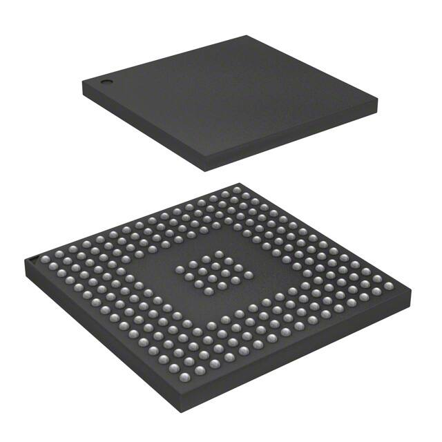
PBGA208 (23 x 23 x 1.96 - Pitch 1.27 mm)
(Plastic Bold Grid Array)
ORDER CODE: ST10F280-JT3
■
A/D converter
– 2X16-channel 10-bit
– 4.85μs conversion time
– One timer for adc channel injection
■
8-channel PWM unit
Memory organization
– 512KB on-chip Flash memory single
voltage with erase/program controller
– 100K erasing/programming cycles
– 20 year data retention time
– Up to 16MB linear address space for code
and data (5MB with CAN)
– 2KB on-chip internal ram (IRAM)
– 16KB extension RAM (XRAM)
■
Serial channels
– Synchronous/async serial channel
– High-speed synchronous channel
■
Fail-safe protection
– Programmable watchdog timer
– Oscillator watchdog
■
Two CAN 2.0b interfaces operating on one or
two can busses (30 or 2x15 message objects)
Fast and flexible bus
– Programmable external bus characteristics
for different address ranges
– 8-bit or 16-bit external data bus
– Multiplexed or demultiplexed external
address/data buses
– Five programmable chip-select signals
– Hold-acknowledge bus arbitration support
■
On-chip bootstrap loader
■
Clock generation
– On-chip PLL
– Direct or prescaled clock input
■
Up to 143 general purpose i/o lines
– Individually programmable as input, output
or special function
– Programmable threshold (hysteresis)
Interrupt
– 8-channel peripheral event controller for
single cycle, interrupt driven data transfer
– 16-priority-level interrupt system with 56
sources, sample-rate down to 25ns
■
Idle and power down modes
■
Maximum cpu frequency 40MHz
■
Package PBGA 208 balls (23 x 23 x 1.96 mm pitch 1.27 mm)
■
Single voltage supply: 5 V ±10% (embedded
regulator for 3.3 V core supply)
■
Temperature range: -40°C to 125°C
■
Two multi-functional general purpose timer
units with 5 timers
■
Two 16-channel capture/compare units
September 2013
This is information on a product in full production.
Doc ID 8673 Rev 4
1/239
www.st.com
1
�Contents
ST10F280
Contents
1
Description . . . . . . . . . . . . . . . . . . . . . . . . . . . . . . . . . . . . . . . . . . . . . . . . 12
2
Ball data . . . . . . . . . . . . . . . . . . . . . . . . . . . . . . . . . . . . . . . . . . . . . . . . . . 14
3
Functional description . . . . . . . . . . . . . . . . . . . . . . . . . . . . . . . . . . . . . . 26
4
Memory organization . . . . . . . . . . . . . . . . . . . . . . . . . . . . . . . . . . . . . . . 27
4.1
5
Visibility of XBUS peripherals . . . . . . . . . . . . . . . . . . . . . . . . . . . . . . . . . . 28
Internal Flash memory . . . . . . . . . . . . . . . . . . . . . . . . . . . . . . . . . . . . . . 31
5.1
Overview . . . . . . . . . . . . . . . . . . . . . . . . . . . . . . . . . . . . . . . . . . . . . . . . . 31
5.2
Operational overview . . . . . . . . . . . . . . . . . . . . . . . . . . . . . . . . . . . . . . . . 31
5.3
5.2.1
Read mode . . . . . . . . . . . . . . . . . . . . . . . . . . . . . . . . . . . . . . . . . . . . . . 31
5.2.2
Instructions and commands . . . . . . . . . . . . . . . . . . . . . . . . . . . . . . . . . . 32
5.2.3
Status register . . . . . . . . . . . . . . . . . . . . . . . . . . . . . . . . . . . . . . . . . . . . 33
5.2.4
Erase operation . . . . . . . . . . . . . . . . . . . . . . . . . . . . . . . . . . . . . . . . . . . 33
5.2.5
Erase suspend . . . . . . . . . . . . . . . . . . . . . . . . . . . . . . . . . . . . . . . . . . . . 33
5.2.6
In-system programming . . . . . . . . . . . . . . . . . . . . . . . . . . . . . . . . . . . . . 33
5.2.7
Read/write protection . . . . . . . . . . . . . . . . . . . . . . . . . . . . . . . . . . . . . . . 33
5.2.8
Power supply, reset . . . . . . . . . . . . . . . . . . . . . . . . . . . . . . . . . . . . . . . . 34
Architectural description . . . . . . . . . . . . . . . . . . . . . . . . . . . . . . . . . . . . . . 34
5.3.1
Read mode . . . . . . . . . . . . . . . . . . . . . . . . . . . . . . . . . . . . . . . . . . . . . . 34
5.3.2
Command mode . . . . . . . . . . . . . . . . . . . . . . . . . . . . . . . . . . . . . . . . . . 34
5.3.3
Flash Status Register . . . . . . . . . . . . . . . . . . . . . . . . . . . . . . . . . . . . . . 35
5.3.4
Flash Protection Register . . . . . . . . . . . . . . . . . . . . . . . . . . . . . . . . . . . 36
5.3.5
Instructions description . . . . . . . . . . . . . . . . . . . . . . . . . . . . . . . . . . . . . 36
5.3.6
Reset processing and initial State . . . . . . . . . . . . . . . . . . . . . . . . . . . . . 41
5.4
Flash memory configuration . . . . . . . . . . . . . . . . . . . . . . . . . . . . . . . . . . . 41
5.5
Application examples . . . . . . . . . . . . . . . . . . . . . . . . . . . . . . . . . . . . . . . . 41
5.6
5.5.1
Handling of Flash addresses . . . . . . . . . . . . . . . . . . . . . . . . . . . . . . . . . 41
5.5.2
Basic Flash access control . . . . . . . . . . . . . . . . . . . . . . . . . . . . . . . . . . 42
5.5.3
Programming examples . . . . . . . . . . . . . . . . . . . . . . . . . . . . . . . . . . . . . 43
Bootstrap loader . . . . . . . . . . . . . . . . . . . . . . . . . . . . . . . . . . . . . . . . . . . . 46
5.6.1
2/239
Entering the bootstrap loader . . . . . . . . . . . . . . . . . . . . . . . . . . . . . . . . 47
Doc ID 8673 Rev 4
�ST10F280
6
Contents
5.6.2
Memory configuration after reset . . . . . . . . . . . . . . . . . . . . . . . . . . . . . . 48
5.6.3
Loading the startup code . . . . . . . . . . . . . . . . . . . . . . . . . . . . . . . . . . . . 49
5.6.4
Exiting bootstrap loader mode . . . . . . . . . . . . . . . . . . . . . . . . . . . . . . . . 50
5.6.5
Choosing the baud rate for the BSL . . . . . . . . . . . . . . . . . . . . . . . . . . . . 50
Central Processing Unit (CPU) . . . . . . . . . . . . . . . . . . . . . . . . . . . . . . . . 52
6.1
Multiplier-accumulator Unit (MAC) . . . . . . . . . . . . . . . . . . . . . . . . . . . . . . 54
6.1.1
7
8
Features . . . . . . . . . . . . . . . . . . . . . . . . . . . . . . . . . . . . . . . . . . . . . . . . . 54
6.2
Instruction set summary . . . . . . . . . . . . . . . . . . . . . . . . . . . . . . . . . . . . . . 55
6.3
MAC coprocessor specific instructions . . . . . . . . . . . . . . . . . . . . . . . . . . . 57
External bus controller . . . . . . . . . . . . . . . . . . . . . . . . . . . . . . . . . . . . . . 62
7.1
Programmable chip select timing control . . . . . . . . . . . . . . . . . . . . . . . . . 63
7.2
READY programmable polarity . . . . . . . . . . . . . . . . . . . . . . . . . . . . . . . . . 63
Interrupt system . . . . . . . . . . . . . . . . . . . . . . . . . . . . . . . . . . . . . . . . . . . 66
8.1
External interrupts . . . . . . . . . . . . . . . . . . . . . . . . . . . . . . . . . . . . . . . . . . 67
8.2
Interrupt registers and vectors location list . . . . . . . . . . . . . . . . . . . . . . . . 68
8.3
Interrupt Control Registers . . . . . . . . . . . . . . . . . . . . . . . . . . . . . . . . . . . . 72
8.4
Exception and error traps list . . . . . . . . . . . . . . . . . . . . . . . . . . . . . . . . . . 73
9
Capture/Compare (CAPCOM) units . . . . . . . . . . . . . . . . . . . . . . . . . . . . 75
10
General purpose timer unit . . . . . . . . . . . . . . . . . . . . . . . . . . . . . . . . . . 78
11
10.1
GPT1 . . . . . . . . . . . . . . . . . . . . . . . . . . . . . . . . . . . . . . . . . . . . . . . . . . . . 78
10.2
GPT2 . . . . . . . . . . . . . . . . . . . . . . . . . . . . . . . . . . . . . . . . . . . . . . . . . . . . 79
PWM module . . . . . . . . . . . . . . . . . . . . . . . . . . . . . . . . . . . . . . . . . . . . . . 81
11.1
Standard PWM module . . . . . . . . . . . . . . . . . . . . . . . . . . . . . . . . . . . . . . 81
11.2
New PWM module: XPWM . . . . . . . . . . . . . . . . . . . . . . . . . . . . . . . . . . . 81
11.2.1
Operating modes . . . . . . . . . . . . . . . . . . . . . . . . . . . . . . . . . . . . . . . . . . 83
11.2.2
XPWM module registers . . . . . . . . . . . . . . . . . . . . . . . . . . . . . . . . . . . . 87
11.2.3
XPWM Control Registers . . . . . . . . . . . . . . . . . . . . . . . . . . . . . . . . . . . . 89
11.2.4
Interrupt request generation . . . . . . . . . . . . . . . . . . . . . . . . . . . . . . . . . 90
11.2.5
XPWM output signals . . . . . . . . . . . . . . . . . . . . . . . . . . . . . . . . . . . . . . 91
11.2.6
XPOLAR Register (polarity of the XPWM channel) . . . . . . . . . . . . . . . . 92
Doc ID 8673 Rev 4
3/239
�Contents
12
ST10F280
Parallel ports . . . . . . . . . . . . . . . . . . . . . . . . . . . . . . . . . . . . . . . . . . . . . . 93
12.1
12.2
Introduction . . . . . . . . . . . . . . . . . . . . . . . . . . . . . . . . . . . . . . . . . . . . . . . 95
12.1.1
Open drain mode . . . . . . . . . . . . . . . . . . . . . . . . . . . . . . . . . . . . . . . . . . 95
12.1.2
Input threshold control . . . . . . . . . . . . . . . . . . . . . . . . . . . . . . . . . . . . . . 96
12.1.3
Output driver control . . . . . . . . . . . . . . . . . . . . . . . . . . . . . . . . . . . . . . . 96
12.1.4
Alternate port functions . . . . . . . . . . . . . . . . . . . . . . . . . . . . . . . . . . . . . 99
Port 0 . . . . . . . . . . . . . . . . . . . . . . . . . . . . . . . . . . . . . . . . . . . . . . . . . . . 100
12.2.1
12.3
Port 1 . . . . . . . . . . . . . . . . . . . . . . . . . . . . . . . . . . . . . . . . . . . . . . . . . . . 103
12.3.1
12.4
Alternate functions of Port 5 . . . . . . . . . . . . . . . . . . . . . . . . . . . . . . . . 121
Port 6 . . . . . . . . . . . . . . . . . . . . . . . . . . . . . . . . . . . . . . . . . . . . . . . . . . . 124
12.8.1
12.9
Alternate functions of Port 4 . . . . . . . . . . . . . . . . . . . . . . . . . . . . . . . . 116
Port 5 . . . . . . . . . . . . . . . . . . . . . . . . . . . . . . . . . . . . . . . . . . . . . . . . . . . 120
12.7.1
12.8
Alternate functions of Port 3 . . . . . . . . . . . . . . . . . . . . . . . . . . . . . . . . 112
Port 4 . . . . . . . . . . . . . . . . . . . . . . . . . . . . . . . . . . . . . . . . . . . . . . . . . . . 115
12.6.1
12.7
Alternate functions of Port 2 . . . . . . . . . . . . . . . . . . . . . . . . . . . . . . . . 107
Port 3 . . . . . . . . . . . . . . . . . . . . . . . . . . . . . . . . . . . . . . . . . . . . . . . . . . . 111
12.5.1
12.6
Alternate functions of Port 1 . . . . . . . . . . . . . . . . . . . . . . . . . . . . . . . . 104
Port 2 . . . . . . . . . . . . . . . . . . . . . . . . . . . . . . . . . . . . . . . . . . . . . . . . . . . 106
12.4.1
12.5
Alternate functions of Port 0 . . . . . . . . . . . . . . . . . . . . . . . . . . . . . . . . 102
Alternate functions of Port 6 . . . . . . . . . . . . . . . . . . . . . . . . . . . . . . . . 125
Port 7 . . . . . . . . . . . . . . . . . . . . . . . . . . . . . . . . . . . . . . . . . . . . . . . . . . . 127
12.9.1
Alternate functions of Port 7 . . . . . . . . . . . . . . . . . . . . . . . . . . . . . . . . 128
12.10 Port 8 . . . . . . . . . . . . . . . . . . . . . . . . . . . . . . . . . . . . . . . . . . . . . . . . . . . 131
12.10.1 Alternate functions of Port 8 . . . . . . . . . . . . . . . . . . . . . . . . . . . . . . . . 132
12.11 XPort 9 . . . . . . . . . . . . . . . . . . . . . . . . . . . . . . . . . . . . . . . . . . . . . . . . . . 134
12.12 XPort 10 . . . . . . . . . . . . . . . . . . . . . . . . . . . . . . . . . . . . . . . . . . . . . . . . . 138
12.12.1 Alternate functions of XPort 10 . . . . . . . . . . . . . . . . . . . . . . . . . . . . . . 138
12.12.2 New disturb protection on analog inputs . . . . . . . . . . . . . . . . . . . . . . . 139
13
4/239
A/D converter . . . . . . . . . . . . . . . . . . . . . . . . . . . . . . . . . . . . . . . . . . . . . 140
13.1
A/D converter module . . . . . . . . . . . . . . . . . . . . . . . . . . . . . . . . . . . . . . . 140
13.2
Multiplexage of two blocks of 16 analog Inputs . . . . . . . . . . . . . . . . . . . 140
13.3
XTIMER peripheral (trigger for ADC channel injection) . . . . . . . . . . . . . 141
13.3.1
Main features . . . . . . . . . . . . . . . . . . . . . . . . . . . . . . . . . . . . . . . . . . . . 142
13.3.2
Register description . . . . . . . . . . . . . . . . . . . . . . . . . . . . . . . . . . . . . . . 143
Doc ID 8673 Rev 4
�ST10F280
Contents
13.3.3
14
Serial channels . . . . . . . . . . . . . . . . . . . . . . . . . . . . . . . . . . . . . . . . . . . 148
14.1
14.2
Asynchronous / Synchronous Serial Interface (ASCO) . . . . . . . . . . . . . 148
14.1.1
ASCO in asynchronous mode . . . . . . . . . . . . . . . . . . . . . . . . . . . . . . . 149
14.1.2
ASCO in synchronous mode . . . . . . . . . . . . . . . . . . . . . . . . . . . . . . . . 151
High speed synchronous serial channel (SSC) . . . . . . . . . . . . . . . . . . . 152
14.2.1
15
Block diagram . . . . . . . . . . . . . . . . . . . . . . . . . . . . . . . . . . . . . . . . . . . 145
Baud rate generation
. . . . . . . . . . . . . . . . . . . . . . . . . . . . . . . . . . . . . 153
CAN modules . . . . . . . . . . . . . . . . . . . . . . . . . . . . . . . . . . . . . . . . . . . . . 155
15.1
15.2
Memory mapping . . . . . . . . . . . . . . . . . . . . . . . . . . . . . . . . . . . . . . . . . . 155
15.1.1
CAN1 . . . . . . . . . . . . . . . . . . . . . . . . . . . . . . . . . . . . . . . . . . . . . . . . . . 155
15.1.2
CAN2 . . . . . . . . . . . . . . . . . . . . . . . . . . . . . . . . . . . . . . . . . . . . . . . . . . 155
CAN bus configurations . . . . . . . . . . . . . . . . . . . . . . . . . . . . . . . . . . . . . 155
15.2.1
Single CAN bus . . . . . . . . . . . . . . . . . . . . . . . . . . . . . . . . . . . . . . . . . . 156
15.2.2
Multiple CAN bus . . . . . . . . . . . . . . . . . . . . . . . . . . . . . . . . . . . . . . . . . 156
15.3
Register and message object organization . . . . . . . . . . . . . . . . . . . . . . 157
15.4
CAN interrupt handling . . . . . . . . . . . . . . . . . . . . . . . . . . . . . . . . . . . . . . 160
15.4.1
Bit timing configuration . . . . . . . . . . . . . . . . . . . . . . . . . . . . . . . . . . . . 162
15.4.2
Mask registers . . . . . . . . . . . . . . . . . . . . . . . . . . . . . . . . . . . . . . . . . . . 163
15.5
The message object . . . . . . . . . . . . . . . . . . . . . . . . . . . . . . . . . . . . . . . . 165
15.6
Arbitration Registers . . . . . . . . . . . . . . . . . . . . . . . . . . . . . . . . . . . . . . . . 168
16
Watchdog timer . . . . . . . . . . . . . . . . . . . . . . . . . . . . . . . . . . . . . . . . . . . 169
17
System reset . . . . . . . . . . . . . . . . . . . . . . . . . . . . . . . . . . . . . . . . . . . . . 171
17.1
17.2
Asynchronous reset (long hardware reset) . . . . . . . . . . . . . . . . . . . . . . 171
17.1.1
Power-on reset . . . . . . . . . . . . . . . . . . . . . . . . . . . . . . . . . . . . . . . . . . . 171
17.1.2
Hardware reset . . . . . . . . . . . . . . . . . . . . . . . . . . . . . . . . . . . . . . . . . . 171
17.1.3
Exit of asynchronous reset state . . . . . . . . . . . . . . . . . . . . . . . . . . . . . 171
Synchronous reset (warm reset) . . . . . . . . . . . . . . . . . . . . . . . . . . . . . . 172
17.2.1
Exit of synchronous reset state . . . . . . . . . . . . . . . . . . . . . . . . . . . . . . 172
17.3
Software reset . . . . . . . . . . . . . . . . . . . . . . . . . . . . . . . . . . . . . . . . . . . . 174
17.4
Watchdog timer reset . . . . . . . . . . . . . . . . . . . . . . . . . . . . . . . . . . . . . . . 174
17.5
RSTOUT pin and bidirectional reset . . . . . . . . . . . . . . . . . . . . . . . . . . . . 175
17.6
Reset circuitry . . . . . . . . . . . . . . . . . . . . . . . . . . . . . . . . . . . . . . . . . . . . 175
Doc ID 8673 Rev 4
5/239
�Contents
18
19
20
ST10F280
Power reduction modes . . . . . . . . . . . . . . . . . . . . . . . . . . . . . . . . . . . . 180
18.1
Idle mode . . . . . . . . . . . . . . . . . . . . . . . . . . . . . . . . . . . . . . . . . . . . . . . . 180
18.2
Power down mode . . . . . . . . . . . . . . . . . . . . . . . . . . . . . . . . . . . . . . . . . 180
18.2.1
Protected power down mode . . . . . . . . . . . . . . . . . . . . . . . . . . . . . . . . 181
18.2.2
Interruptable power down mode . . . . . . . . . . . . . . . . . . . . . . . . . . . . . 181
Special function register overview . . . . . . . . . . . . . . . . . . . . . . . . . . . 185
19.1
Identification registers . . . . . . . . . . . . . . . . . . . . . . . . . . . . . . . . . . . . . . 194
19.2
System configuration registers . . . . . . . . . . . . . . . . . . . . . . . . . . . . . . . . 196
Electrical characteristics . . . . . . . . . . . . . . . . . . . . . . . . . . . . . . . . . . . 205
20.1
Absolute maximum ratings . . . . . . . . . . . . . . . . . . . . . . . . . . . . . . . . . . . 205
20.2
Parameter interpretation . . . . . . . . . . . . . . . . . . . . . . . . . . . . . . . . . . . . . 205
20.3
DC characteristics . . . . . . . . . . . . . . . . . . . . . . . . . . . . . . . . . . . . . . . . . 205
20.4
20.3.1
A/D converter characteristics . . . . . . . . . . . . . . . . . . . . . . . . . . . . . . . . 208
20.3.2
Conversion timing control . . . . . . . . . . . . . . . . . . . . . . . . . . . . . . . . . . 209
AC characteristics . . . . . . . . . . . . . . . . . . . . . . . . . . . . . . . . . . . . . . . . . 210
20.4.1
Test waveforms . . . . . . . . . . . . . . . . . . . . . . . . . . . . . . . . . . . . . . . . . . 210
20.4.2
Definition of internal timing . . . . . . . . . . . . . . . . . . . . . . . . . . . . . . . . . 210
20.4.3
Clock generation modes . . . . . . . . . . . . . . . . . . . . . . . . . . . . . . . . . . . 211
20.4.4
Prescaler operation . . . . . . . . . . . . . . . . . . . . . . . . . . . . . . . . . . . . . . . 212
20.4.5
Direct drive . . . . . . . . . . . . . . . . . . . . . . . . . . . . . . . . . . . . . . . . . . . . . . 212
20.4.6
Oscillator Watchdog (OWD) . . . . . . . . . . . . . . . . . . . . . . . . . . . . . . . . . 213
20.4.7
Phase locked loop . . . . . . . . . . . . . . . . . . . . . . . . . . . . . . . . . . . . . . . . 213
20.4.8
External clock drive XTAL1 . . . . . . . . . . . . . . . . . . . . . . . . . . . . . . . . . 214
20.4.9
Memory cycle variables . . . . . . . . . . . . . . . . . . . . . . . . . . . . . . . . . . . . 215
20.4.10 Multiplexed bus . . . . . . . . . . . . . . . . . . . . . . . . . . . . . . . . . . . . . . . . . . 215
20.4.11 Demultiplexed bus . . . . . . . . . . . . . . . . . . . . . . . . . . . . . . . . . . . . . . . . 222
20.4.12 CLKOUT and READY . . . . . . . . . . . . . . . . . . . . . . . . . . . . . . . . . . . . . 227
20.4.13 External bus arbitration . . . . . . . . . . . . . . . . . . . . . . . . . . . . . . . . . . . . 229
20.4.14 High-speed synchronous serial interface (SSC) timing . . . . . . . . . . . . 231
21
6/239
Package information . . . . . . . . . . . . . . . . . . . . . . . . . . . . . . . . . . . . . . . 235
21.1
ECOPACK® . . . . . . . . . . . . . . . . . . . . . . . . . . . . . . . . . . . . . . . . . . . . . . 235
21.2
PBGA 208 (23 x 23 x 1.96 mm) mechanical data . . . . . . . . . . . . . . . . . 235
Doc ID 8673 Rev 4
�ST10F280
Contents
22
Ordering information . . . . . . . . . . . . . . . . . . . . . . . . . . . . . . . . . . . . . . 237
23
Revision history . . . . . . . . . . . . . . . . . . . . . . . . . . . . . . . . . . . . . . . . . . 238
Doc ID 8673 Rev 4
7/239
�List of tables
ST10F280
List of tables
Table 1.
Table 2.
Table 3.
Table 4.
Table 5.
Table 6.
Table 7.
Table 8.
Table 9.
Table 10.
Table 11.
Table 12.
Table 13.
Table 14.
Table 15.
Table 16.
Table 17.
Table 18.
Table 19.
Table 20.
Table 21.
Table 22.
Table 23.
Table 24.
Table 25.
Table 26.
Table 27.
Table 28.
Table 29.
Table 30.
Table 31.
Table 32.
Table 33.
Table 34.
Table 35.
Table 36.
Table 37.
Table 38.
Table 39.
Table 40.
Table 41.
Table 42.
Table 43.
Table 44.
Table 45.
Table 46.
Table 47.
Table 48.
8/239
Ball description . . . . . . . . . . . . . . . . . . . . . . . . . . . . . . . . . . . . . . . . . . . . . . . . . . . . . . . . . . 15
512 Kbyte Flash memory block organization . . . . . . . . . . . . . . . . . . . . . . . . . . . . . . . . . . . 32
Instructions . . . . . . . . . . . . . . . . . . . . . . . . . . . . . . . . . . . . . . . . . . . . . . . . . . . . . . . . . . . . . 39
Instruction set summary . . . . . . . . . . . . . . . . . . . . . . . . . . . . . . . . . . . . . . . . . . . . . . . . . . . 55
MAC coprocessor specific instructions . . . . . . . . . . . . . . . . . . . . . . . . . . . . . . . . . . . . . . . . 58
Pointer post-modification combinations for IDXi and Rwn . . . . . . . . . . . . . . . . . . . . . . . . . 60
MAC registers referenced as ‘CoReg‘ . . . . . . . . . . . . . . . . . . . . . . . . . . . . . . . . . . . . . . . . 60
Interrupt sources . . . . . . . . . . . . . . . . . . . . . . . . . . . . . . . . . . . . . . . . . . . . . . . . . . . . . . . . . 68
Exceptions or error conditions that can arise during run-time. . . . . . . . . . . . . . . . . . . . . . . 74
Compare modes . . . . . . . . . . . . . . . . . . . . . . . . . . . . . . . . . . . . . . . . . . . . . . . . . . . . . . . . . 77
CAPCOM timer input frequencies, resolution and periods . . . . . . . . . . . . . . . . . . . . . . . . . 77
GPT1 timer input frequencies, resolution and periods . . . . . . . . . . . . . . . . . . . . . . . . . . . . 79
GPT2 timer input frequencies, resolution and period . . . . . . . . . . . . . . . . . . . . . . . . . . . . . 80
PWM unit frequencies and resolution at 40MHz CPU clock . . . . . . . . . . . . . . . . . . . . . . . . 81
XPWM module channel specific register addresses. . . . . . . . . . . . . . . . . . . . . . . . . . . . . . 88
XPWM frequency . . . . . . . . . . . . . . . . . . . . . . . . . . . . . . . . . . . . . . . . . . . . . . . . . . . . . . . . 88
POCON registers . . . . . . . . . . . . . . . . . . . . . . . . . . . . . . . . . . . . . . . . . . . . . . . . . . . . . . . . 98
Port 2 alternate function . . . . . . . . . . . . . . . . . . . . . . . . . . . . . . . . . . . . . . . . . . . . . . . . . . 108
Port 3 alternate functions . . . . . . . . . . . . . . . . . . . . . . . . . . . . . . . . . . . . . . . . . . . . . . . . . 112
Port 4 alternate functions . . . . . . . . . . . . . . . . . . . . . . . . . . . . . . . . . . . . . . . . . . . . . . . . . 117
Port 5 alternate functions . . . . . . . . . . . . . . . . . . . . . . . . . . . . . . . . . . . . . . . . . . . . . . . . . 121
Port 6 alternate functions . . . . . . . . . . . . . . . . . . . . . . . . . . . . . . . . . . . . . . . . . . . . . . . . . 125
Port 7 alternate functions . . . . . . . . . . . . . . . . . . . . . . . . . . . . . . . . . . . . . . . . . . . . . . . . . 128
Port 8 alternate functions . . . . . . . . . . . . . . . . . . . . . . . . . . . . . . . . . . . . . . . . . . . . . . . . . 132
XPort 10 alternate functions . . . . . . . . . . . . . . . . . . . . . . . . . . . . . . . . . . . . . . . . . . . . . . . 138
The different counting Modes . . . . . . . . . . . . . . . . . . . . . . . . . . . . . . . . . . . . . . . . . . . . . . 142
Timer registers mapping . . . . . . . . . . . . . . . . . . . . . . . . . . . . . . . . . . . . . . . . . . . . . . . . . . 145
Commonly used baud rates by reload value and deviation errors . . . . . . . . . . . . . . . . . . 150
Commonly used baud rates by reload value and deviation errors . . . . . . . . . . . . . . . . . . 152
Synchronous baud rate and reload values . . . . . . . . . . . . . . . . . . . . . . . . . . . . . . . . . . . . 154
INTID values and corresponding interrupt sources . . . . . . . . . . . . . . . . . . . . . . . . . . . . . 161
Functions of complementary bit of message control register . . . . . . . . . . . . . . . . . . . . . . 166
WDTCON bits value on different resets . . . . . . . . . . . . . . . . . . . . . . . . . . . . . . . . . . . . . . 170
WDTREL reload value . . . . . . . . . . . . . . . . . . . . . . . . . . . . . . . . . . . . . . . . . . . . . . . . . . . 170
Reset event definition . . . . . . . . . . . . . . . . . . . . . . . . . . . . . . . . . . . . . . . . . . . . . . . . . . . . 171
PORT0 latched configuration for the different resets . . . . . . . . . . . . . . . . . . . . . . . . . . . . 178
PORT0 bit latched into the different registers after reset . . . . . . . . . . . . . . . . . . . . . . . . . 179
Special function registers listed by name . . . . . . . . . . . . . . . . . . . . . . . . . . . . . . . . . . . . . 185
X registers listed by name . . . . . . . . . . . . . . . . . . . . . . . . . . . . . . . . . . . . . . . . . . . . . . . . 192
Stack size selection . . . . . . . . . . . . . . . . . . . . . . . . . . . . . . . . . . . . . . . . . . . . . . . . . . . . . 197
Absolute maximum ratings . . . . . . . . . . . . . . . . . . . . . . . . . . . . . . . . . . . . . . . . . . . . . . . . 205
DC characteristics. . . . . . . . . . . . . . . . . . . . . . . . . . . . . . . . . . . . . . . . . . . . . . . . . . . . . . . 205
A/D converter characteristics . . . . . . . . . . . . . . . . . . . . . . . . . . . . . . . . . . . . . . . . . . . . . . 208
ADC sampling and conversion timing . . . . . . . . . . . . . . . . . . . . . . . . . . . . . . . . . . . . . . . . 209
CPU frequency generation . . . . . . . . . . . . . . . . . . . . . . . . . . . . . . . . . . . . . . . . . . . . . . . . 211
External clock drive XTAL1. . . . . . . . . . . . . . . . . . . . . . . . . . . . . . . . . . . . . . . . . . . . . . . . 214
Memory cycle variables . . . . . . . . . . . . . . . . . . . . . . . . . . . . . . . . . . . . . . . . . . . . . . . . . . 215
Multiplexed bus characteristics . . . . . . . . . . . . . . . . . . . . . . . . . . . . . . . . . . . . . . . . . . . . . 215
Doc ID 8673 Rev 4
�ST10F280
Table 49.
Table 50.
Table 51.
Table 52.
Table 53.
Table 54.
Table 55.
Table 56.
List of tables
Demultiplexed bus characteristics . . . . . . . . . . . . . . . . . . . . . . . . . . . . . . . . . . . . . . . . . . 222
CLKOUT and READY characteristics . . . . . . . . . . . . . . . . . . . . . . . . . . . . . . . . . . . . . . . . 227
External bus arbitration . . . . . . . . . . . . . . . . . . . . . . . . . . . . . . . . . . . . . . . . . . . . . . . . . . . 229
SSC master timing . . . . . . . . . . . . . . . . . . . . . . . . . . . . . . . . . . . . . . . . . . . . . . . . . . . . . . 231
SSC slave timing . . . . . . . . . . . . . . . . . . . . . . . . . . . . . . . . . . . . . . . . . . . . . . . . . . . . . . . 233
PBGA 208 (23 x 23 x 1.96 mm) mechanical data. . . . . . . . . . . . . . . . . . . . . . . . . . . . . . . 236
Device summary . . . . . . . . . . . . . . . . . . . . . . . . . . . . . . . . . . . . . . . . . . . . . . . . . . . . . . . . 237
Document revision history . . . . . . . . . . . . . . . . . . . . . . . . . . . . . . . . . . . . . . . . . . . . . . . . 238
Doc ID 8673 Rev 4
9/239
�List of figures
ST10F280
List of figures
Figure 1.
Figure 2.
Figure 3.
Figure 4.
Figure 5.
Figure 6.
Figure 7.
Figure 8.
Figure 9.
Figure 10.
Figure 11.
Figure 12.
Figure 13.
Figure 14.
Figure 15.
Figure 16.
Figure 17.
Figure 18.
Figure 19.
Figure 20.
Figure 21.
Figure 22.
Figure 23.
Figure 24.
Figure 25.
Figure 26.
Figure 27.
Figure 28.
Figure 29.
Figure 30.
Figure 31.
Figure 32.
Figure 33.
Figure 34.
Figure 35.
Figure 36.
Figure 37.
Figure 38.
Figure 39.
Figure 40.
Figure 41.
Figure 42.
Figure 43.
Figure 44.
Figure 45.
Figure 46.
Figure 47.
Figure 48.
10/239
Logic symbol . . . . . . . . . . . . . . . . . . . . . . . . . . . . . . . . . . . . . . . . . . . . . . . . . . . . . . . . . . . . 13
Ball Configuration (bottom view) . . . . . . . . . . . . . . . . . . . . . . . . . . . . . . . . . . . . . . . . . . . . . 14
Block diagram . . . . . . . . . . . . . . . . . . . . . . . . . . . . . . . . . . . . . . . . . . . . . . . . . . . . . . . . . . . 26
ST10F280 on-chip memory mapping . . . . . . . . . . . . . . . . . . . . . . . . . . . . . . . . . . . . . . . . . 29
Bootstrap loader sequence . . . . . . . . . . . . . . . . . . . . . . . . . . . . . . . . . . . . . . . . . . . . . . . . . 47
Hardware provisions to activate the BSL . . . . . . . . . . . . . . . . . . . . . . . . . . . . . . . . . . . . . . 49
Memory configuration after reset . . . . . . . . . . . . . . . . . . . . . . . . . . . . . . . . . . . . . . . . . . . . 49
Baud rate deviation between host and ST10F280 . . . . . . . . . . . . . . . . . . . . . . . . . . . . . . . 51
CPU block diagram (MAC unit not included) . . . . . . . . . . . . . . . . . . . . . . . . . . . . . . . . . . . 52
MAC unit architecture . . . . . . . . . . . . . . . . . . . . . . . . . . . . . . . . . . . . . . . . . . . . . . . . . . . . . 55
Chip select delay . . . . . . . . . . . . . . . . . . . . . . . . . . . . . . . . . . . . . . . . . . . . . . . . . . . . . . . . 63
CAPCOM unit block diagram . . . . . . . . . . . . . . . . . . . . . . . . . . . . . . . . . . . . . . . . . . . . . . . 75
Block diagram of CAPCOM timers T0 and T7 . . . . . . . . . . . . . . . . . . . . . . . . . . . . . . . . . . 76
Block diagram of CAPCOM timers T1 and T . . . . . . . . . . . . . . . . . . . . . . . . . . . . . . . . . . . 76
Block diagram of GPT1. . . . . . . . . . . . . . . . . . . . . . . . . . . . . . . . . . . . . . . . . . . . . . . . . . . . 79
Block diagram of GPT2. . . . . . . . . . . . . . . . . . . . . . . . . . . . . . . . . . . . . . . . . . . . . . . . . . . . 80
Block diagram of PWM module . . . . . . . . . . . . . . . . . . . . . . . . . . . . . . . . . . . . . . . . . . . . . 81
SFRs and port pins associated with the XPWM module. . . . . . . . . . . . . . . . . . . . . . . . . . . 82
XPWM channel block diagram . . . . . . . . . . . . . . . . . . . . . . . . . . . . . . . . . . . . . . . . . . . . . . 82
Operation and output waveform in mode 0. . . . . . . . . . . . . . . . . . . . . . . . . . . . . . . . . . . . . 84
Operation and output waveform in mode 1. . . . . . . . . . . . . . . . . . . . . . . . . . . . . . . . . . . . . 85
Operation and output waveform in burst mode. . . . . . . . . . . . . . . . . . . . . . . . . . . . . . . . . . 86
Operation and output waveform in single shot mode . . . . . . . . . . . . . . . . . . . . . . . . . . . . . 87
XPWM output signal generation . . . . . . . . . . . . . . . . . . . . . . . . . . . . . . . . . . . . . . . . . . . . . 91
SFRs associated with the parallel ports . . . . . . . . . . . . . . . . . . . . . . . . . . . . . . . . . . . . . . . 94
XBUS registers associated with the parallel ports . . . . . . . . . . . . . . . . . . . . . . . . . . . . . . . 95
Output drivers in push/pull mode and in open drain mode . . . . . . . . . . . . . . . . . . . . . . . . . 95
Hysteresis for special input thresholds . . . . . . . . . . . . . . . . . . . . . . . . . . . . . . . . . . . . . . . . 96
Port 0 I/O and alternate functions . . . . . . . . . . . . . . . . . . . . . . . . . . . . . . . . . . . . . . . . . . . 102
Block diagram of a Port 0 pin . . . . . . . . . . . . . . . . . . . . . . . . . . . . . . . . . . . . . . . . . . . . . . 103
Port 1 I/O and alternate functions . . . . . . . . . . . . . . . . . . . . . . . . . . . . . . . . . . . . . . . . . . . 105
Block diagram of a Port 1 pin . . . . . . . . . . . . . . . . . . . . . . . . . . . . . . . . . . . . . . . . . . . . . . 106
Port 2 I/O and alternate functions . . . . . . . . . . . . . . . . . . . . . . . . . . . . . . . . . . . . . . . . . . . 109
Block diagram of a Port 2 pin . . . . . . . . . . . . . . . . . . . . . . . . . . . . . . . . . . . . . . . . . . . . . . 110
Port 3 I/O and alternate functions . . . . . . . . . . . . . . . . . . . . . . . . . . . . . . . . . . . . . . . . . . . 113
Block diagram of Port 3 pin with alternate input or alternate output function . . . . . . . . . . 114
Block diagram of pins P3.15 (CLKOUT) and P3.12 (BHE/WRH) . . . . . . . . . . . . . . . . . . . 115
Port 4 I/O and alternate functions . . . . . . . . . . . . . . . . . . . . . . . . . . . . . . . . . . . . . . . . . . . 117
Block diagram of a Port 4 pin . . . . . . . . . . . . . . . . . . . . . . . . . . . . . . . . . . . . . . . . . . . . . . 118
Block diagram of P4.4 and P4.5 pins . . . . . . . . . . . . . . . . . . . . . . . . . . . . . . . . . . . . . . . . 119
Block diagram of P4.6 and P4.7 pins . . . . . . . . . . . . . . . . . . . . . . . . . . . . . . . . . . . . . . . . 120
Port 5 I/O and alternate functions . . . . . . . . . . . . . . . . . . . . . . . . . . . . . . . . . . . . . . . . . . . 122
Block diagram of a Port 5 pin . . . . . . . . . . . . . . . . . . . . . . . . . . . . . . . . . . . . . . . . . . . . . . 122
Port 6 I/O and alternate functions . . . . . . . . . . . . . . . . . . . . . . . . . . . . . . . . . . . . . . . . . . . 125
Block diagram of Port 6 pins with an alternate output function . . . . . . . . . . . . . . . . . . . . . 126
Port 7 I/O and alternate functions . . . . . . . . . . . . . . . . . . . . . . . . . . . . . . . . . . . . . . . . . . . 129
Block diagram of Port 7 pins P7.3...P7.0 . . . . . . . . . . . . . . . . . . . . . . . . . . . . . . . . . . . . . 129
Block diagram of Port 7 pins P7.7...P7.4 . . . . . . . . . . . . . . . . . . . . . . . . . . . . . . . . . . . . . 130
Doc ID 8673 Rev 4
�ST10F280
List of figures
Figure 49.
Figure 50.
Figure 51.
Figure 52.
Figure 53.
Figure 54.
Figure 55.
Figure 56.
Figure 57.
Figure 58.
Figure 59.
Figure 60.
Figure 61.
Figure 62.
Figure 63.
Figure 64.
Figure 65.
Figure 66.
Figure 67.
Figure 68.
Figure 69.
Figure 70.
Figure 71.
Figure 72.
Figure 73.
Figure 74.
Figure 75.
Figure 76.
Figure 77.
Figure 78.
Figure 79.
Figure 80.
Figure 81.
Figure 82.
Port 8 I/O and alternate functions . . . . . . . . . . . . . . . . . . . . . . . . . . . . . . . . . . . . . . . . . . . 132
Block diagram of Port 8 pins P8.7...P8.0 . . . . . . . . . . . . . . . . . . . . . . . . . . . . . . . . . . . . . 133
PORT10 I/O and alternate functions. . . . . . . . . . . . . . . . . . . . . . . . . . . . . . . . . . . . . . . . . 139
Block diagram . . . . . . . . . . . . . . . . . . . . . . . . . . . . . . . . . . . . . . . . . . . . . . . . . . . . . . . . . . 141
XTIMER block diagram . . . . . . . . . . . . . . . . . . . . . . . . . . . . . . . . . . . . . . . . . . . . . . . . . . . 145
XADCINJ timer output . . . . . . . . . . . . . . . . . . . . . . . . . . . . . . . . . . . . . . . . . . . . . . . . . . . 146
External connection for ADC channel injection. . . . . . . . . . . . . . . . . . . . . . . . . . . . . . . . . 147
Asynchronous mode of serial channel ASC0 . . . . . . . . . . . . . . . . . . . . . . . . . . . . . . . . . . 149
Synchronous mode of serial channel ASC0 . . . . . . . . . . . . . . . . . . . . . . . . . . . . . . . . . . . 151
Synchronous serial channel SSC block diagram . . . . . . . . . . . . . . . . . . . . . . . . . . . . . . . 153
Single CAN bus multiple interfaces - multiple transceivers. . . . . . . . . . . . . . . . . . . . . . . 156
Single CAN bus dual interfaces - single transceiver . . . . . . . . . . . . . . . . . . . . . . . . . . . . 156
Connection to two different CAN buses (e.g. for gateway application). . . . . . . . . . . . . . . 157
CAN module address map . . . . . . . . . . . . . . . . . . . . . . . . . . . . . . . . . . . . . . . . . . . . . . . . 158
Bit timing definition . . . . . . . . . . . . . . . . . . . . . . . . . . . . . . . . . . . . . . . . . . . . . . . . . . . . . . 162
Message object address map . . . . . . . . . . . . . . . . . . . . . . . . . . . . . . . . . . . . . . . . . . . . . . 166
Asynchronous reset timing . . . . . . . . . . . . . . . . . . . . . . . . . . . . . . . . . . . . . . . . . . . . . . . . 172
Synchronous warm reset (short low pulse on RSTIN) . . . . . . . . . . . . . . . . . . . . . . . . . . . 173
Synchronous warm reset (long low pulse on RSTIN) . . . . . . . . . . . . . . . . . . . . . . . . . . . 174
Internal (simplified) reset circuitry . . . . . . . . . . . . . . . . . . . . . . . . . . . . . . . . . . . . . . . . . . . 177
Minimum external reset circuitry . . . . . . . . . . . . . . . . . . . . . . . . . . . . . . . . . . . . . . . . . . . . 177
External reset hardware circuitry . . . . . . . . . . . . . . . . . . . . . . . . . . . . . . . . . . . . . . . . . . . 178
External RC circuit on RPD pin for exiting power down mode with external interrupt . . . 183
Simplified power down exit circuitry . . . . . . . . . . . . . . . . . . . . . . . . . . . . . . . . . . . . . . . . . 184
Power down exit sequence when using an external interrupt (PLL x 2) . . . . . . . . . . . . . . 184
Supply / idle current as a function of operating frequency . . . . . . . . . . . . . . . . . . . . . . . . 207
Input / output waveforms . . . . . . . . . . . . . . . . . . . . . . . . . . . . . . . . . . . . . . . . . . . . . . . . . 210
Float waveforms . . . . . . . . . . . . . . . . . . . . . . . . . . . . . . . . . . . . . . . . . . . . . . . . . . . . . . . . 210
Generation mechanisms for the CPU clock . . . . . . . . . . . . . . . . . . . . . . . . . . . . . . . . . . . 211
Approximated maximum PLL Jitter . . . . . . . . . . . . . . . . . . . . . . . . . . . . . . . . . . . . . . . . . . 214
External clock drive XTAL1. . . . . . . . . . . . . . . . . . . . . . . . . . . . . . . . . . . . . . . . . . . . . . . . 215
External memory cycle: multiplexed bus, with / without read / write delay, normal ALE. . 218
External memory cycle: multiplexed bus, with / without read / write delay, extended ALE219
External memory cycle: multiplexed bus, with / without read / write delay, normal ALE,
read / write chip select . . . . . . . . . . . . . . . . . . . . . . . . . . . . . . . . . . . . . . . . . . . . . . . . . . . 220
External memory cycle: multiplexed bus, with / without read / write delay, extended ALE,
read / write chip select . . . . . . . . . . . . . . . . . . . . . . . . . . . . . . . . . . . . . . . . . . . . . . . . . . . 221
External memory cycle: demultiplexed bus, with / without read / write delay, normal ALE224
External memory cycle: demultiplexed bus, with / without read / write delay, extended ALE
. . . . . . . . . . . . . . . . . . . . . . . . . . . . . . . . . . . . . . . . . . . . . . . . . . . . . . . . . . . . . . . . . . . . . 225
External memory cycle: demultiplexed bus, with / without read / write delay, normal ALE,
read / write chip select . . . . . . . . . . . . . . . . . . . . . . . . . . . . . . . . . . . . . . . . . . . . . . . . . . . 226
External memory cycle: demultiplexed bus, no read / write delay, extended ALE, read /write
chip select . . . . . . . . . . . . . . . . . . . . . . . . . . . . . . . . . . . . . . . . . . . . . . . . . . . . . . . . . . . . . 227
CLKOUT and READY . . . . . . . . . . . . . . . . . . . . . . . . . . . . . . . . . . . . . . . . . . . . . . . . . . . . 229
External bus arbitration, releasing the bus . . . . . . . . . . . . . . . . . . . . . . . . . . . . . . . . . . . . 230
External bus arbitration, (regaining the bus) . . . . . . . . . . . . . . . . . . . . . . . . . . . . . . . . . . 231
SSC master timing . . . . . . . . . . . . . . . . . . . . . . . . . . . . . . . . . . . . . . . . . . . . . . . . . . . . . . 232
SSC slave timing . . . . . . . . . . . . . . . . . . . . . . . . . . . . . . . . . . . . . . . . . . . . . . . . . . . . . . . 234
Package outline PBGA 208 (23 x 23 x 1.96 mm) . . . . . . . . . . . . . . . . . . . . . . . . . . . . . . . 235
Figure 83.
Figure 84.
Figure 85.
Figure 86.
Figure 87.
Figure 88.
Figure 89.
Figure 90.
Figure 91.
Figure 92.
Figure 93.
Doc ID 8673 Rev 4
11/239
�Description
1
ST10F280
Description
The ST10F280 is a new derivative of the STMicroelectronics® ST10 family of 16-bit singlechip CMOS microcontrollers. It combines high CPU performance (up to 20 million
instructions per second) with high peripheral functionality and enhanced I/O-capabilities. It
also provides on-chip high-speed single voltage FLASH memory, on-chip high-speed RAM,
and clock generation via PLL.
ST10F280 is processed in 0.35μm CMOS technology. The MCU core and the logic is
supplied with a 5V to 3.3V on chip voltage regulator. The part is supplied with a single 5V
supply and I/Os work at 5V.
The device is upward compatible with the ST10F269 device, with the following set of
differences:
12/239
●
Two supply pins (DC1,DC2) on the PBGA-208 package are used for decoupling the
internally generated 3.3V core logic supply. Do not connect these two pins to 5.0V
external supply. Instead, these pins should be connected to a decoupling capacitor
(ceramic type, value ≥ 330nF).
●
The A/D Converter characteristics stay identical but 16 new input channel are added. A
bit in a new register (XADCMUX) control the multiplexage between the first block of 16
channel (on Port5) and the second block (on XPort10). The conversion result registers
stay identical and the software management can determine the block in use. A new
dedicated timer controls now the ADC channel injection mode on the input CC31
(P7.7). The output of this timer is visible on a dedicated pin (XADCINJ) to emulate this
new functionality.
●
A second XPWM peripheral (4 new channels) is added. Four dedicated pins are
reserved for the outputs (XPWM[0:3])
●
A new general purpose I/O port named XPORT9 (16 bits) is added. Due to the bit
addressing management, it will be different from other standard general purpose I/O
ports.
Doc ID 8673 Rev 4
�ST10F280
Description
Figure 1.
Logic symbol
9''
966
;7$/�
;7$/�
3RUW��
���ELW
567,1
567287
3RUW��
���ELW
9$5()
3RUW��
���ELW
9$*1'
3RUW��
���ELW
10,
($
5($'<
$/(
3RUW��
��ELW
67��)���
5'
:5�:5/
3RUW��
��ELW
3RUW��
��ELW
3RUW��
���ELW
3RUW��
��ELW
;3RUW��
���ELW
;3RUW��
���ELW
;3:0
��ELW
;$'&,1'&�
'&�
'HFRXSOLQJ�FDSDFLWRU�IRU�LQWHUQDO�UHJXODWRU
("1($'5�����
Doc ID 8673 Rev 4
13/239
�Ball data
2
ST10F280
Ball data
The ST10F280 package is a PBGA of 23 x 23 x 1.96 mm. The pitch of the balls is 1.27 mm.
The signal assignment of the 208 balls is described in Figure 2 for the configuration and in
Table 1 for the ball signal assignment. This package has 25 additional thermal balls.
Figure 2.
Ball Configuration (bottom view)
1
U1
U
XP10.15
T1
T
XP10.14
P
XP10.7
XP10.3
F
H2
G2
DC1
F2
VSS
E
VDD
D1
D
C
P6.7
P6.3
P6.2
VSS
P8.1
P2.6
P9
P2.1
P2.9
P10
P2.5
P2.10
P2.11
R11
P2.12
P11
P2.14
P2.13
T12
P2.15
R12
P3.0
P12
P3.2
13
U13
VSS
T13
P3.1
R13
P3.3
P13
P3.5
L7
L8
VSS
K7
J7
H7
G7
VSS
J10
VSS
H10
VSS
G9
VSS
VSS
VSS
H9
VSS
G8
VSS
K10
VSS
G10
VSS
VSS
VSS
VSS
P3.7
P4.2
K14
K11
VSS
P4.6
J11
VSS
RD
H14
H11
VSS
P0.2
G14
G11
VSS
P0.5
P0.10
E14
P0.15
P6.0
D5
xpwm.0
D6
VSS
C5
NMI
P1.14
VSS
D8
P1.13
C7
P1.15
B6
A5
A4
VSS
C6
B5
RSTOUT
D7
VSS
P1.9
C8
P1.12
B7
A6
D9
P1.11
P1.6
C9
P1.8
B8
A7
D10
P1.7
B9
VSS
A8
RSTIN
VSS
XTAL1
XTAL2
P1.10
VSS
2
3
4
5
6
7
8
P1.3
B10
VSS
A9
VDD
P1.2
C10
P1.4
A10
D11
XP9.14
C11
P1.0
B11
P1.1
A11
VDD
P1.5
VSS
9
10
11
Doc ID 8673 Rev 4
D12
XP9.11
C12
XP9.13
B12
XP9.15
A12
VDD
12
D13
XP9.5
C13
XP9.10
B13
XP9.12
A13
15
U15
VDD
T15
VSS
R15
P3.8
P15
P3.11
N15
VSS
M15
P4.1
L15
P4.4
K15
P4.7
J15
J14
P6.6
B4
A3
P3.6
P14
F14
C4
B3
P3.4
R14
L14
L11
VSS
VSS
J9
VSS
H8
VSS
L10
VSS
K9
VSS
J8
VSS
P8.5
L9
VSS
K8
VSS
P7.0
D4
P6.1
VSS
T14
P3.13
P7.6
P6.5
14
U14
P3.10
E4
xpwm.3 xpwm.1
xpwm.2
P2.2
P2.8
R10
DC2
T11
12
U12
F4
C3
A2
1
14/239
P6.4
P2.4
R9
P8
P5.14
VSS
P8.3
D3
B2
A1
A
P8.0
P2.3
T10
11
U11
M14
G4
E3
C2
B1
B
P8.2
D2
C1
P8.6
F3
E2
P5.10
H4
G3
P8.4
P5.15
VSS
P2.7
T9
R8
P7
J4
P7.1
H3
P8.7
P5.11
K4
P7.5
J3
VSS
E1
XADCINJ
K3
P7.2
P5.6
P2.0
R7
P6
VDD
T8
10
U10
XP10.4
L4
J2
F1
XP10.5
L3
P7.4
P5.12
R6
P5.7
VSS
T7
9
U9
N14
XP10.0
P7.3
G1
G
XP10.8
P5.13
8
U8
N4
XP10.1
K2
P5.8
7
U7
T6
P5
XP10.2
VDD
H1
P5.3
P4
M4
P7.7
P5.9
R5
M3
L2
J1
P5.4
6
U6
T5
M2
VSS
J
H
P5.1
N3
XP10.6
P5.5
R4
P3
N2
K1
K
P5.2
5
U5
T4
XP10.11 XP10.10 XP10.9
L1
L
VAGND
R3
P2
M1
M
P5.0
4
U4
T3
XP10.13 XP10.12
N1
N
VAREF
R2
P1
3
U3
T2
R1
R
2
U2
D14
XP9.2
C14
XP9.6
B14
XP9.9
A14
VSS
VDD
13
14
WR
H15
P0.1
G15
P0.4
F15
P0.8
E15
P0.12
D15
XP9.0
C15
XP9.3
B15
XP9.7
A15
16
U16
VSS
T16
VSS
R16
P3.9
P16
P3.12
N16
P4.0
M16
P4.3
L16
P4.5
K16
VSS
J16
READY
H16
P0.0
G16
P0.3
F16
P0.6
E16
P0.9
D16
P0.13
C16
XP9.1
B16
XP9.4
A16
17
U17
VSS
U
T17
P3.15
T
R17
VSS
R
P17
VDD
P
N17
VSS
N
M17
RPD
M
L17
VDD
L
K17
VSS
K
J17
ALE
J
H17
EA
H
G17
VDD
G
F17
VSS
F
E17
P0.7
E
D17
P0.11
D
C17
P0.14
C
B17
VSS
B
A17
XP9.8
VSS
VSS
15
16
17
A
�ST10F280
Ball data
Table 1.
Symbol
P6.0 – P6.7
P8.0 – P8.7
Ball description
Ball
Type
number
Function
I/O
Port 6 is an 8-bit bidirectional I/O port. It is bit-wise programmable
for input or output via direction bits. For a pin configured as input,
the output driver is put into high-impedance state. Port 6 outputs
can be configured as push/pull or open drain drivers.
The following Port 6 pins also serve for alternate functions:
E4
O
P6.0 CS0 Chip Select 0 Output
D3
O
P6.1 CS1 Chip Select 1 Output
B1
O
P6.2 CS2 Chip Select 2 Output
C1
O
P6.3 CS3 Chip Select 3 Output
D2
O
P6.4 CS4 Chip Select 4 Output
E3
I
P6.5 HOLD External Master Hold Request Input
F4
O
P6.6 HLDA Hold Acknowledge Output
D1
O
P6.7 BREQ Bus Request Output
I/O
Port 8 is an 8-bit bidirectional I/O port. It is bit-wise programmable
for input or output via direction bits. For a pin configured as input,
the output driver is put into high-impedance state. Port 8 outputs
can be configured as push/pull or open drain drivers. The input
threshold of Port 8 is selectable (TTL or special).
The following Port 8 pins also serve for alternate functions:
E2
I/O
P8.0 CC16IO CAPCOM2: CC16 Capture Input / Compare Output
F3
I/O
P8.1 CC17IO CAPCOM2: CC17 Capture Input / Compare Output
F2
I/O
P8.2 CC18IO CAPCOM2: CC18 Capture Input / Compare Output
G3
I/O
P8.3 CC19IO CAPCOM2: CC19 Capture Input / Compare Output
G2
I/O
P8.4 CC20IO CAPCOM2: CC20 Capture Input / Compare Output
H4
I/O
P8.5 CC21IO CAPCOM2: CC21 Capture Input / Compare Output
H3
I/O
P8.6 CC22IO CAPCOM2: CC22 Capture Input / Compare Output
H2
I/O
P8.7 CC23IO CAPCOM2: CC23 Capture Input / Compare Output
Doc ID 8673 Rev 4
15/239
�Ball data
ST10F280
Table 1.
Symbol
P7.0 – P7.7
XP10.0 –
XP10.15
16/239
Ball description (continued)
Ball
Type
number
Function
I/O
Port 7 is an 8-bit bidirectional I/O port. It is bit-wise programmable
for input or output via direction bits. For a pin configured as input,
the output driver is put into high-impedance state. Port 7 outputs
can be configured as push/pull or open drain drivers. The input
threshold of Port 7 is selectable (TTL or special).
The following Port 7 pins also serve for alternate functions:
J4
O
P7.0 POUT0 PWM Channel 0 Output
J3
O
P7.1 POUT1 PWM Channel 1 Output
J2
O
P7.2 POUT2 PWM Channel 2 Output
J1
O
P7.3 POUT3 PWM Channel 3 Output
K2
I/O
P7.4 CC28IO CAPCOM2: CC28 Capture Input / Compare Output
K3
I/O
P7.5 CC29IO CAPCOM2: CC29 Capture Input / Compare Output
K4
I/O
P7.6 CC30IO CAPCOM2: CC30 Capture Input / Compare Output
L2
I/O
P7.7 CC31IO CAPCOM2: CC31 Capture Input / Compare Output
I
XPort 10 is a 16-bit input-only port with Schmitt-Trigger
characteristics.
The pins of XPort10 also serve as the analog input channels (up to
16) for the A/D converter, where XP10.X equals ANx (Analog input
channel x).
I
I
I
I
I
I
I
I
I
I
I
I
I
I
I
I
XP10.0
XP10.1
XP10.2
XP10.3
XP10.4
XP10.5
XP10.6
XP10.7
XP10.8
XP10.9
XP10.10
XP10.11
XP10.12
XP10.13
XP10.14
XP10.15
M4
M3
M2
M1
N4
N3
N2
N1
P4
P3
P2
P1
R2
R1
T1
U1
Doc ID 8673 Rev 4
�ST10F280
Ball data
Table 1.
Ball description (continued)
Symbol
P5.0 – P5.15
Ball
Type
number
Function
I
Port 5 is a 16-bit input-only port with Schmitt-Trigger
characteristics.
The pins of Port 5 also serve as the analog input channels (up to
16) for the A/D converter, where P5.x equals ANx (Analog input
channel x), or they serve as timer inputs:
T2
I
P5.0
R3
I
P5.1
T3
I
P5.2
R4
I
P5.3
T4
I
P5.4
U4
I
P5.5
P5
I
P5.6
R5
I
P5.7
T5
I
P5.8
U5
I
P5.9
P6
I
P5.10 T6EUD GPT2 Timer T6 External Up / Down Control Input
R6
I
P5.11 T5EUD GPT2 Timer T5 External Up / Down Control Input
T6
I
P5.12 T6IN GPT2 Timer T6 Count Input
U6
I
P5.13 T5IN GPT2 Timer T5 Count Input
P7
I
P5.14 T4EUD GPT1 Timer T4 External Up / Down Control Input
R7
I
P5.15 T2EUD GPT1 Timer T2 External Up / Down Control Input
Doc ID 8673 Rev 4
17/239
�Ball data
ST10F280
Table 1.
Ball description (continued)
Symbol
P2.0 – P2.15
18/239
Ball
Type
number
Function
I/O
Port 2 is a 16-bit bidirectional I/O port. It is bit-wise programmable
for input or output via direction bits. For a pin configured as input,
the output driver is put into high-impedance state. Port 2 outputs
can be configured as push/pull or open drain drivers. The input
threshold of Port 2 is selectable (TTL or special).
The following Port 2 pins also serve for alternate functions:
T7
I/O
P2.0 CC0IO CAPCOM: CC0 Capture Input / Compare Output
P8
I/O
P2.1 CC1IO CAPCOM: CC1 Capture Input / Compare Output
R8
I/O
P2.2 CC2IO CAPCOM: CC2 Capture Input / Compare Output
T8
I/O
P2.3 CC3IO CAPCOM: CC3 Capture Input / Compare Output
T9
I/O
P2.4 CC4IO CAPCOM: CC4 Capture Input / Compare Output
P9
I/O
P2.5 CC5IO CAPCOM: CC5 Capture Input / Compare Output
R9
I/O
P2.6 CC6IO CAPCOM: CC6 Capture Input / Compare Output
U9
I/O
P2.7 CC7IO CAPCOM: CC7 Capture Input / Compare Output
T10
I/O
I
P2.8 CC8IO CAPCOM: CC8 Capture Input / Compare Output,
EX0IN Fast External Interrupt 0 Input
R10
I/O
I
P2.9 CC9IO CAPCOM: CC9 Capture Input / Compare Output,
EX1IN Fast External Interrupt 1 Input
P10
I/O
I
P2.10 CC10IO CAPCOM: CC10 Capture Input / Compare Output,
EX2IN Fast External Interrupt 2 Input
T11
I/O
I
P2.11 CC11IO CAPCOM: CC11 Capture Input / Compare Output,
EX3IN Fast External Interrupt 3 Input
R11
I/O
I
P2.12 CC12IO CAPCOM: CC12 Capture Input / Compare Output,
EX4IN Fast External Interrupt 4 Input
U12
I/O
I
P2.13 CC13IO CAPCOM: CC13 Capture Input / Compare Output,
EX5IN Fast External Interrupt 5 Input
P11
I/O
I
P2.14 CC14IO CAPCOM: CC14 Capture Input / Compare Output,
EX6IN Fast External Interrupt 6 Input
T12
I/O
I
I
P2.15 CC15IO CAPCOM: CC15 Capture Input / Compare Output,
EX7IN Fast External Interrupt 7 Input
T7IN CAPCOM2 Timer T7 Count Input
Doc ID 8673 Rev 4
�ST10F280
Ball data
Table 1.
Ball description (continued)
Symbol
Ball
Type
number
I/O
P3.0 - P3.13,
P3.15
Function
Port 3 is a 15-bit (P3.14 is missing) bidirectional I/O port. It is bitwise programmable for input or output via direction bits. For a pin
configured as input, the output driver is put into high-impedance
state. Port 3 outputs can be configured as push/pull or open drain
drivers. The input threshold of Port 3 is selectable (TTL or special).
The following Port 3 pins also serve for alternate functions:
R12
I
P3.0 T0IN CAPCOM Timer T0 Count Input
T13
O
P3.1 T6OUT GPT2 Timer T6 Toggle Latch Output
P12
I
P3.2 CAPIN GPT2 Register CAPREL Capture Input
R13
O
P3.3 T3OUT GPT1 Timer T3 Toggle Latch Output
T14
I
P3.4 T3EUD GPT1 Timer T3 External Up / Down Control Input
P13
I
P3.5 T4IN GPT1 Timer T4 Input for Count / Gate / Reload / Capture
R14
I
P3.6 T3IN GPT1 Timer T3 Count / Gate Input
P14
I
P3.7 T2IN GPT1 Timer T2 Input for Count / Gate / Reload / Capture
R15
I/O
P3.8 MRST SSC Master-Receive / Slave-Transmit I/O
R16
I/O
P3.9 MTSR SSC Master-Transmit / Slave-Receive O/I
N14
I/O
P3.10 TxD0 ASC0 Clock / Data Output (Asynchronous /
Synchronous)
P15
O
P3.11 RxD0 ASC0 Data Input (Asynchronous) or I/O
(Synchronous)
P16
O
P3.12 BHE External Memory High Byte Enable Signal, WRH
External Memory High Byte Write Strobe
M14
I/O
P3.13 SCLK SSC Master Clock Output / Slave Clock Input
T17
O
P3.15 CLKOUT System Clock Output (= CPU Clock)
Doc ID 8673 Rev 4
19/239
�Ball data
ST10F280
Table 1.
Symbol
P4.0 – P4.7
RD
WR/WRL
Ball
Type
number
Function
I/O
Port 4 is an 8-bit bidirectional I/O port. It is bit-wise programmable
for input or output via direction bits. For a pin configured as input,
the output driver is put into high-impedance state. The input
threshold is selectable (TTL or special).
P4.6 & P4.7 outputs can be configured as push-pull or open-drain
drivers.
In case of an external bus configuration, Port 4 can be used to
output the segment address lines:
N16
O
P4.0 A16 Least Significant Segment Address Line
M15
O
P4.1 A17 Segment Address Line
L14
O
P4.2 A18 Segment Address Line
M16
O
P4.3 A19 Segment Address Line
L15
O
I
P4.4 A20 Segment Address Line
CAN2_RxD CAN2 Receive Data Input
L16
O
I
P4.5 A21 Segment Address Line
CAN1_RxD CAN1 Receive Data Input
K14
O
O
P4.6 A22 Segment Address Line, CAN_TxD
CAN1_TxD CAN1 Transmit Data Output
K15
O
O
P4.7 A23 Most Significant Segment Address Line
CAN2_TxD CAN2 Transmit Data Output
J14
O
External Memory Read Strobe. RD is activated for every external
instruction or data read access.
O
External Memory Write Strobe. In WR-mode this pin is activated for
every external data write access. In WRL-mode this pin is activated
for low byte data write accesses on a 16-bit bus, and for every data
write access on an 8-bit bus. See WRCFG in register SYSCON for
mode selection.
J15
READY/
READY
J16
I
Ready Input. The active level is programmable. When the Ready
function is enabled, the selected inactive level at this pin during an
external memory access will force the insertion of memory cycle
time waitstates until the pin returns to the selected active level.
ALE
J17
O
Address Latch Enable Output. Can be used for latching the
address into external memory or an address latch in the
multiplexed bus modes.
I
External Access Enable pin. A low level at this pin during and after
Reset forces the ST10F280 to begin instruction execution out of
external memory. A high level forces execution out of the internal
Flash Memory.
EA
20/239
Ball description (continued)
H17
Doc ID 8673 Rev 4
�ST10F280
Ball data
Table 1.
Ball description (continued)
Symbol
PORT0:
P0L.0 - P0L.7,
P0H.0 - P0H.7
Ball
Type
number
Function
I/O
PORT0 consists of the two 8-bit bidirectional I/O ports P0L and
P0H. It is bit-wise programmable for input or output via direction
bits. For a pin configured as input, the output driver is put into highimpedance state.
In case of an external bus configuration, PORT0 serves as the
address (A) and address/data (AD) bus in multiplexed bus modes
and as the data (D) bus in demultiplexed bus modes.
Demultiplexed bus modes:
Data Path Width: 8-bit 16-bit
P0L.0 – P0L.7: D0 - D7 D0 - D7
P0H.0 – P0H.7: I/O D8 - D15
Multiplexed bus modes:
Data Path Width: 8-bit 16-bit
P0L.0 – P0L.7: AD0 - AD7 AD0 - AD7
P0H.0 – P0H.7: A8 - A15 AD8 - AD15
H16
I/O
P0L.0
H15
I/O
P0L.1
H14
I/O
P0L.2
G16
I/O
P0L.3
G15
I/O
P0L.4
G14
I/O
P0L.5
F16
I/O
P0L.6
E17
I/O
P0L.7
F15
I/O
P0H.0
E16
I/O
P0H.1
F14
I/O
P0H.2
D17
I/O
P0H.3
E15
I/O
P0H.4
D16
I/O
P0H.5
C17
I/O
P0H.6
E14
I/O
P0H.7
Doc ID 8673 Rev 4
21/239
�Ball data
ST10F280
Table 1.
Symbol
XPORT9.0 XPORT9.15
22/239
Ball description (continued)
Ball
Type
number
Function
I/O
XPort 9 is a 16-bit bidirectional I/O port. It is bit-wise programmable
for input or output via direction bits. For a pin configured as input,
the output driver is put into high-impedance state. XPort 9 outputs
can be configured as push/pull or open drain drivers.
D15
I/O
XPORT9.0
C16
I/O
XPORT9.1
D14
I/O
XPORT9.2
C15
I/O
XPORT9.3
B16
I/O
XPORT9.4
D13
I/O
XPORT9.5
C14
I/O
XPORT9.6
B15
I/O
XPORT9.7
A15
I/O
XPORT9.8
B14
I/O
XPORT9.9
C13
I/O
XPORT9.10
D12
I/O
XPORT9.11
B13
I/O
XPORT9.12
C12
I/O
XPORT9.13
D11
I/O
XPORT9.14
B12
I/O
XPORT9.15
Doc ID 8673 Rev 4
�ST10F280
Ball data
Table 1.
Ball description (continued)
Symbol
PORT1:
P1L.0 - P1L.7,
P1H.0 - P1H.7
XTAL1
XTAL2
RSTIN
RSTOUT
Ball
Type
number
Function
I/O
PORT1 consists of the two 8-bit bidirectional I/O ports P1L and
P1H. It is bit-wise programmable for input or output via direction
bits. For a pin configured as input, the output driver is put into highimpedance state. PORT1 is used as the 16-bit address bus (A) in
demultiplexed bus modes and also after switching from a
demultiplexed bus mode to a multiplexed bus mode. The following
PORT1 pins also serve for alternate functions:
C11
I/O
P1L.0
B11
I/O
P1L.1
D10
I/O
P1L.2
C10
I/O
P1L.3
B10
I/O
P1L.4
A10
I/O
P1L.5
D9
I/O
P1L.6
C9
I/O
P1L.7
C8
I/O
P1H.0
D8
I/O
P1H.1
A7
I/O
P1H.2
B7
I/O
P1H.3
C7
I
P1H.4 CC24IO CAPCOM2: CC24 Capture Input
D7
I
P1H.5 CC25IO CAPCOM2: CC25 Capture Input
C5
I
P1H.6 CC26IO CAPCOM2: CC26 Capture Input
C6
I
P1H.7 CC27IO CAPCOM2: CC27 Capture Input
A5
I
XTAL1: Input to the oscillator amplifier and input to the internal
clock generator
O
XTAL2: Output of the oscillator amplifier circuit.
To clock the device from an external source, drive XTAL1, while
leaving XTAL2 unconnected. Minimum and maximum high/low and
rise/fall times specified in the AC Characteristics must be observed.
I
Reset Input with Schmitt-Trigger characteristics. A low level at this
pin for a specified duration while the oscillator is running resets the
ST10F280. An internal pull-up resistor permits power-on reset
using only a capacitor connected to VSS.
In bidirectional reset mode (enabled by setting bit BDRSTEN in
SYSCON register), the RSTIN line is pulled low for the duration of
the internal reset sequence.
O
Internal Reset Indication Output. This pin is set to a low level when
the part is executing either a hardware, a software or a watchdog
timer reset. RSTOUT remains low until the EINIT (end of
initialization) instruction is executed.
A6
A3
B4
Doc ID 8673 Rev 4
23/239
�Ball data
ST10F280
Table 1.
Symbol
24/239
Ball description (continued)
Ball
Type
number
Function
NMI
C4
I
Non-Maskable Interrupt Input. A high to low transition at this pin
causes the CPU to vector to the NMI trap routine. If bit PWDCFG =
‘0’ in SYSCON register, when the PWRDN (power down)
instruction is executed, the NMI pin must be low in order to force
the ST10F280 to go into power down mode. If NMI is high and
PWDCFG =’0’, when PWRDN is executed, the part will continue to
run in normal mode.
If not used, pin NMI should be pulled high externally.
XPWM.0
D4
O
XPWM Channel 0 Output
XPWM.1
C3
O
XPWM Channel 1 Output
XPWM.2
B2
O
XPWM Channel 2 Output
XPWM.3
C2
O
XPWM Channel 3 Output
XADCINJ
L3
O
Output trigger for ADC channel injection
VAREF
U2
-
Reference voltage for the A/D converter.
VAGND
U3
-
Reference ground for the A/D converter.
RPD
M17
I/O
Timing pin for the return from powerdown circuit and
synchronous/asynchronous reset selection.
DC1
G1
O
3.3V Decoupling pin: a decoupling capacitor of ~330 nF must be
connected between this pin and nearest VSS pin.
DC2
U11
O
3.3V Decoupling pin: a decoupling capacitor of ~330 nF must be
connected between this pin and VSS nearest pin.
VDD
A2
A9
A12
A14
E1
K1
U8
U15
P17
L17
G17
-
Digital Supply Voltage: + 5 V during normal operation, idle mode
and power down mode
Doc ID 8673 Rev 4
�ST10F280
Ball data
Table 1.
Symbol
VSS
Ball description (continued)
Ball
Type
number
A1
A4
A8
A11
A13
A16
A17
B3
B5
B6
B8
B9
B17
D5
D6
F1
F17
G4
H1
K16
K17
L1
L4
N15
N17
R17
T15
T16
U7
U10
U13
U14
U16
U17
-
Function
Digital ground.
Doc ID 8673 Rev 4
25/239
�Functional description
3
ST10F280
Functional description
The architecture of the ST10F280 combines advantages of both RISC and CISC processors
and an advanced peripheral subsystem. The block diagram gives an overview of the
different on-chip components and the high bandwidth internal bus structure of the
ST10F280.
Block diagram
��
��
�
���.�%\WH
)ODVK�0HPRU\
�.�%\WH
,QWHUQDO
5$0
��
&38�&RUH�DQG�0$&�8QLW
:DWFKGRJ
��
3(&
��.�%\WH
;5$0
,QWHUUXSW�&RQWUROOHU
��
���9�
3RUW��
3RUW��
�
3RUW��
3RUW��
��
��
;3257��
;3257�
;3:0
��
��
�
;7,0(5
;7$/�
9ROWDJH
5HJXODWRU
&$3&20�
%5*
&$3&20�
66&
%5*
3:0
$6&�XVDUW
�
*37�
��
���%LW�$'&
��
*37�
&$1�
([WHUQDO�%XV�
&RQWUROOHU
3����&$1�B5['
3����&$1�B7['
;7$/�
&$1�
3RUW�� 3RUW�� 3RUW��
3����&$1�B5['
3����&$1�B7['
2VFLOODWRU
DQG�3//
��
3RUW��
Figure 3.
��
3RUW��
�
�
3����7ULJJHU�IRU�$'&
FKDQQHO�LQMHFWLRQ
([WHUQDO�FRQQH[LRQ
;$'&,1("1($'5�����
26/239
Doc ID 8673 Rev 4
�ST10F280
4
Memory organization
Memory organization
The memory space of the ST10F280 is configured in a unified memory architecture. Code
memory, data memory, registers and I/O ports are organized within the same linear address
space of 16M Bytes. The entire memory space can be accessed byte-wise or word-wise.
Particular portions of the on-chip memory have additionally been made directly bit
addressable.
FLASH: 512K Bytes of on-chip single voltage FLASH memory.
IRAM: 2K Bytes of on-chip internal RAM (dual-port) is provided as a storage for data,
system stack, general purpose register banks and code. The register bank can consist of up
to 16 word-wide (R0 to R15) and/or byte-wide (RL0, RH0, …, RL7, RH7) general purpose
registers. Base address is 00’F600h, upper address is 00’FDFFh.
XRAM: 16K Bytes of on-chip extension RAM (single port XRAM) is provided as a storage
for data, user stack and code. The XRAM is a single bank, connected to the internal XBUS
and are accessed like an external memory in 16-bit demultiplexed bus-mode without
waitstate or read/write delay (50ns access at 40MHz CPU clock). Byte and word access is
allowed.
The XRAM address range is 00’8000h - 00’BFFFh if enabled (XPEN set bit 2 of SYSCON
register-, and XRAMEN set bit 2 of XPERCON register-). If bit XRAMEN or XPEN is
cleared, then any access in the address range 00’8000h 00’BFFFh will be directed to
external memory interface, using the BUSCONx register corresponding to address
matching ADDRSELx register
As the XRAM appears like external memory, it cannot be used for the ST10F280’s system
stack or register banks. The XRAM is not provided for single bit storage and therefore is not
bit addressable.
SFR/ESFR: 1024 bytes (2 * 512 bytes) of address space is reserved for the special function
register areas. SFRs are word-wide registers which are used for controlling and monitoring
functions of the different on-chip units.
CAN1: Address range 00’EF00h 00’EFFFh is reserved for the CAN1 Module access. The
CAN1 is enabled by setting XPEN bit 2 of the SYSCON register and bit 0 of the new
XPERCON register. Accesses to the CAN Module use demultiplexed addresses and a 16bit data bus (byte accesses are possible). Two waitstates give an access time of 100 ns at
40MHz CPU clock. No tristate waitstate is used.
CAN2: Address range 00’EE00h 00’EEFFh is reserved for the CAN2 Module access. The
CAN2 is enabled by setting XPEN bit 2 of the SYSCON register and bit 1 of the new
XPERCON register. Accesses to the CAN Module use demultiplexed addresses and a 16bit data bus (byte accesses are possible). Two waitstates give an access time of 100 ns at
40MHz CPU clock. No tristate waitstate is used.
In order to meet the needs of designs where more memory is required than is provided on
chip, up to 16M Bytes of external RAM and/or ROM can be connected to the microcontroller.
If one or the two CAN modules are used, Port 4 can not be programmed to output all 8
segment address lines. Thus, only 4 segment address lines can be used, reducing the
external memory space to 5M Bytes (1M Byte per CS line).
XPWM: Address range 00’EC00h 00’ECFFh is reserved for the XPWM Module access. The
XPWM is enabled by setting XPEN bit 2 of the SYSCON register and bit 4 of the new
XPERCON register. Accesses to the XPWM Module use demultiplexed addresses and a 16-
Doc ID 8673 Rev 4
27/239
�Memory organization
ST10F280
bit data bus (byte accesses are possible). Two waitstates give an access time of 100 ns at
40MHz CPU clock. No tristate waitstate is used.
XPORT9, XTIMER, XPORT10, XADCMUX: Address range 00’C000h 00’C3FFh is reserved
for the XPORT9, XPORT10, XTIMER and XADCMUX peripherals access. The XPORT9,
XTIMER, XPORT10, XADCMUX are enabled by setting XPEN bit 2 of the SYSCON register
and the bit 3 of the new XPERCON register. Accesses to the XPORT9, XTIMER, XPORT10
and XADCMUX modules use a 16-bit demultiplexed bus mode without waitstate or
read/write delay (50ns access at 40MHz CPU clock). Byte and word access is allowed.
4.1
Visibility of XBUS peripherals
The XBUS peripherals can be separately selected for being visible to the user by means of
corresponding selection bits in the XPERCON register. If not selected (not activated with
XPERCON bit) before the global enabling with XPEN-bit in SYSCON register, the
corresponding address space, port pins and interrupts are not occupied by the peripheral,
thus the peripheral is not visible and not available. SYSCON register is described in
Section 19.2: System configuration registers.
28/239
Doc ID 8673 Rev 4
�ST10F280
Memory organization
ST10F280 on-chip memory mapping
6HJPHQW��
6HJPHQW��
6HJPHQW��
6HJPHQW��
��¶����
%ORFN��� ���.�%\WHV
��
��¶����
��
��¶����
5$0��6)5�DQG�;�SKHULSKHUDOV�DUH�
PDSSHG�LQWR�WKH�DGGUHVV�VSDFH�
��¶))))
%ORFN�� ���.�%\WHV
��
��¶����
6)5�������%\WHV
��¶)(��
��¶)'))
%ORFN�� ���.�%\WHV
�&
��¶����
��
��¶����
,5$0����.�%\WHV
��¶)���
%ORFN�� ���.�%\WHV
��¶)�))
(6)5�������%\WHV
��
6HJPHQW��
%ORFN�� ���.�%\WHV
��
��¶����
��¶)���
��¶()))
��¶����
��
��
%ORFN�
%ORFN�
%ORFN�
&$1��������%\WHV
��¶()��
��¶(())
&$1��������%\WHV
��¶((��
��
��¶&���
��¶%)))
��¶(&))
��
6HJPHQW��
Figure 4.
;5$0� ���.�%\WHV
;3:0
��¶����
��¶(&��
��
��¶����
��¶����
%ORFN�� ��.�%\WHV
%ORFN�� ��.�%\WHV
��¶&�))
%ORFN�� ���.�%\WHV
��
;3257��;7,0(5
;3257��
;$'&08;
��¶&���
��¶����
'DWD
3DJH
1XPEHU
$EVROXWH
0HPRU\
$GGUHVV
,QWHUQDO
)ODVK
0HPRU\
�%ORFNV������DQG���PD\�EH�UHPDSSHG�IURP�VHJPHQW���WR�VHJPHQW���E\�VHWWLQJ�6