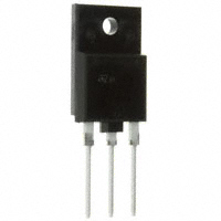
ST2001FX
HIGH VOLTAGE FAST-SWITCHING
NPN POWER TRANSISTOR
NEW SERIES, ENHANCED PERFORMANCE
FULLY INSULATED PACKAGE (U.L.
COMPLIANT) FOR EASY MOUNTING
HIGH VOLTAGE CAPABILITY
HIGH SWITCHING SPEED
TIGTHER hfe CONTROL
IMPROVED RUGGEDNESS
�
�
�
�
�
�
APPLICATIONS:
HORIZONTAL DEFLECTION FOR COLOR TVS
OVER 21 INCHES AND 15 INCHES MONITORS
�
ISOWATT218FX
c
u
d
DESCRIPTION
The d e vice is m an u fa ctu r ed u sin g Diff us ed
Collector technology for more stable operation Vs
base drive circuit variations resulting in very low
worst case dissipation.
e
t
le
)
s
t(
o
r
P
INTERNAL SCHEMATIC DIAGRAM
)
s
(
ct
o
s
b
O
-
u
d
o
r
P
e
ABSOLUTE MAXIMUM RATINGS
t
e
l
o
Symbol
Value
Unit
1500
V
VCBO
Collector-Base Voltage (IE = 0)
VCEO
Collector-Emitter Voltage (IB = 0)
600
V
VEBO
Emitter-Base Voltage (IC = 0)
7
V
Collector Current
10
A
Collector Peak Current (tp < 5 ms)
20
A
Base Current
7
A
bs
O
Parameter
IC
ICM
IB
Ptot
Total Dissipation at Tc = 25 °C
Vins
Insulation Withstand Voltage (RMS) from All Three
Leads to External Heatsink
Tstg
Storage Temperature
Tj
October 2003
Max. Operating Junction Temperature
63
W
2500
V
–65 to 150
°C
150
°C
1/7
�ST2001FX
THERMAL DATA
Rthj-case
Thermal Resistance Junction-case
Max
2
°C/W
ELECTRICAL CHARACTERISTICS (Tj = 25 °C unless otherwise specified)
Symbol
Parameter
Test Conditions
Min.
Typ.
Max.
Unit
1
2
mA
mA
1
mA
Collector Cut-off
Current (VBE = 0)
VCE = 1500 V
VCE = 1500 V
Emitter Cut-off Current
(IC = 0)
VEB = 7 V
VCEO(sus)*
Collector-Emitter
Sustaining Voltage
(IB = 0)
IC = 100 mA
VCE(sat)*
Collector-Emitter
Saturation Voltage
IC = 5 A
IB = 1.25 A
1.5
V
VBE(sat)*
Base-Emitter
Saturation Voltage
IC = 5 A
IB = 1.25 A
1.2
V
DC Current Gain
IC = 6 A
IC = 6 A
VCE = 1 V
VCE = 5 V
IC = 5 A
IBon (END) = 850 mA
LBB(off) = 2 µH
VBB(off) = -2.5 V
fh = 64 KHz
(See Figure 1)
ICES
IEBO
hFE*
INDUCTIVE LOAD
Storage Time
Fall Time
ts
tf
Tj = 125 °C
600
4.5
5
* Pulsed: Pulse duration = 300 µs, duty cycle = 1.5 %.
e
t
le
)
s
(
ct
u
d
o
r
P
e
t
e
l
o
s
b
O
2/7
V
o
s
b
O
-
)
s
t(
9
o
r
P
c
u
d
2.6
0.2
3
0.4
µs
µs
�ST2001FX
Safe Operating Area
Derating Curve
Thermal Impedance
Output Characteristics
c
u
d
e
t
le
)
s
(
ct
u
d
o
Collector-Emitter Saturation Voltage
r
P
e
)
s
t(
o
r
P
o
s
b
O
-
Base-Emitter Saturation Voltage
t
e
l
o
s
b
O
3/7
�ST2001FX
DC Current Gain
DC Current Gain
Power Losses
Inductive Load Switchin Times
c
u
d
e
t
le
)
s
(
ct
u
d
o
Reverse Biased Safe Operating Area
r
P
e
t
e
l
o
s
b
O
4/7
o
s
b
O
-
o
r
P
)
s
t(
�ST2001FX
Figure 1: Inductive Load Switching Test Circuit
c
u
d
e
t
le
)
s
(
ct
)
s
t(
o
r
P
o
s
b
O
-
u
d
o
r
P
e
t
e
l
o
s
b
O
5/7
�ST2001FX
ISOWATT218FX MECHANICAL DATA
mm.
DIM.
MIN.
TYP.
inch
MAX.
MIN.
A
5.30
5.70
0.209
TYP.
0.224
C
2.80
3.20
0.110
0.126
D
3.10
3.50
0.122
0.138
D1
1.80
2.20
0.071
0.087
E
0.80
1.10
0.031
0.043
F
0.65
0.95
0.026
0.037
F2
1.80
2.20
0.071
0.087
G
10.30
11.50
0.406
0.453
G1
5.45
0.215
H
15.30
15.70
0.602
L
9.80
10.20
0.386
L2
22.80
23.20
0.898
L3
26.30
26.70
1.035
L4
43.20
44.40
1.701
4.30
4.70
0.169
L6
24.30
24.70
0.957
L7
14.60
15.00
N
1.80
R
3.80
DIA
3.40
)
s
t(
0.618
0.402
uc
d
o
r
P
e
let
L5
)
s
(
ct
0.575
o
s
b
O
-
0.913
1.051
1.748
0.185
0.972
0.591
2.20
0.071
0.087
4.20
0.150
0.165
3.80
0.134
0.150
u
d
o
r
P
e
t
e
l
o
s
b
O
- Weight : 5.6 g (typ.)
- Maximum Torque (applied to mounting flange) Recommended: 0.55 Nm; Maximum: 1 Nm
- The side of the dissipator must be flat within 80 mm
6/7
MAX.
�ST2001FX
c
u
d
e
t
le
)
s
(
ct
)
s
t(
o
r
P
o
s
b
O
-
u
d
o
r
P
e
t
e
l
o
Information furnished is believed to be accurate and reliable. However, STMicroelectronics assumes no responsibility for the
consequences of use of such information nor for any infringement of patents or other rights of third parties which may result from
its use. No license is granted by implication or otherwise under any patent or patent rights of STMicroelectronics. Specifications
mentioned in this publication are subject to change without notice. This publication supersedes and replaces all information
previously supplied. STMicroelectronics products are not authorized for use as critical components in life support devices or
systems without express written approval of STMicroelectronics.
© The ST logo is a registered trademark of STMicroelectronics
s
b
O
© 2003 STMicroelectronics - Printed in Italy - All Rights Reserved
STMicroelectronics GROUP OF COMPANIES
Australia - Brazil - Canada - China - Finland - France - Germany - Hong Kong - India - Israel - Italy - Japan - Malaysia - Malta - Morocco
Singapore - Spain - Sweden - Switzerland - United Kingdom - United States.
© http://www.st.com
7/7
�
很抱歉,暂时无法提供与“ST2001FX”相匹配的价格&库存,您可以联系我们找货
免费人工找货