ST755C
Adjustable inverting negative output
current mode PWM regulators
Features
■
2.7V to 11V input to adjustable negative output
conversion
■
1W guaranteed output power
(VI > 4.5V, TA ≤ 70°C)
■
68% typ. efficiency at 6V
■
Very low quiescent current: 1.2mA in on mode,
10µA in shut down mode
■
Soft start
■
Very low noise output
■
160KHz fixed frequency oscillator
■
Mixed bipolar-CMOS technology
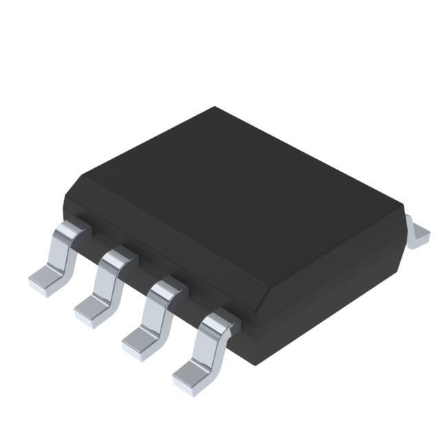
SO-8
)
s
t(
and TA = 0°C to 70°C) and 275mA (typical value
at TA = 25°C, VO = -5V).
c
u
d
o
r
A logic controlled shut down pin that interfaces
directly with microprocessor reduces supply
current to only 10mA. Input to Output differential
voltage is limited to VI+|VO| 4.5V, VO = -5V
P
e
et
O
)
s
(
t
c
u
d
o
r
eP
t
e
ol
s
b
O
Table 1.
July 2007
Device summary
Part number
Package
Packaging
ST755C
ST755CD-TR
SO-8 (tape & reel)
Rev. 5
1/16
www.st.com
16
�ST755C
Contents
1
Diagram . . . . . . . . . . . . . . . . . . . . . . . . . . . . . . . . . . . . . . . . . . . . . . . . . . . 3
2
Pin configuration . . . . . . . . . . . . . . . . . . . . . . . . . . . . . . . . . . . . . . . . . . . 4
3
Maximum ratings . . . . . . . . . . . . . . . . . . . . . . . . . . . . . . . . . . . . . . . . . . . . 5
4
Electrical characteristics . . . . . . . . . . . . . . . . . . . . . . . . . . . . . . . . . . . . . 6
5
Application information . . . . . . . . . . . . . . . . . . . . . . . . . . . . . . . . . . . . . . 7
6
Application circuit . . . . . . . . . . . . . . . . . . . . . . . . . . . . . . . . . . . . . . . . . . . 8
7
Typical performance characteristics . . . . . . . . . . . . . . . . . . . . . . . . . . . 10
8
Package mechanical data . . . . . . . . . . . . . . . . . . . . . . . . . . . . . . . . . . . . 12
9
Revision history . . . . . . . . . . . . . . . . . . . . . . . . . . . . . . . . . . . . . . . . . . . 15
)
s
t(
c
u
d
o
r
l
o
bs
O
)
s
(
t
c
u
d
o
r
eP
t
e
ol
s
b
O
2/16
P
e
et
�ST755C
Diagram
1
Diagram
Figure 1.
Schematic diagram
)
s
t(
c
u
d
o
r
l
o
bs
P
e
et
O
)
s
(
t
c
u
d
o
r
eP
t
e
ol
s
b
O
3/16
�Pin configuration
ST755C
2
Pin configuration
Figure 2.
Pin connections (top view)
Table 2.
Pin description
Pin N°
Symbol
Name and function
1
SHDN
SHUT-DOWN control (VCC = ON, GND = Shutdown)
2
VREF
Reference output voltage: (1.25V)
3
SS
Soft start
4
CC
Compensation input
5
VO
Negative output voltage
6
GND
7
LX
8
VCC
Switch output
s
(
t
c
u
d
Supply voltage input
s
b
O
4/16
l
o
bs
O
)
Ground
o
r
eP
t
e
ol
c
u
d
o
r
)
s
t(
P
e
et
�ST755C
Maximum ratings
3
Maximum ratings
Table 3.
Absolute maximum ratings
Symbol
VCC
VSHDN
Parameter
DC input voltage to GND (1)
Shutdown voltage, SS Voltage, CC Voltage
VLX
Switch voltage (LX to VCC)
VFB
Feedback voltage (VO to GND)
ILX
Peak switch current
PTOT
Value
Unit
-0.3 to 12
V
-0.3 to (VCC + 0.3)
V
-12.5 to + 0.3
V
-11 to + 0.9
V
2
A
470
mW
Continuous power dissipation at TA = 70°C (SO-8)
Top
Operating junction temperature range (C series)
-40 to 185
°C
Tstg
Storage temperature range
-55 to +150
°C
)
s
t(
1. The input to output differential voltage is limited to VCC+|VO|
很抱歉,暂时无法提供与“ST755CD”相匹配的价格&库存,您可以联系我们找货
免费人工找货