ST8034T, ST8034AT, ST8034P,
ST8034C
16-pin smartcard interfaces
Datasheet - production data
Card clock frequency up to 20 MHz,
programmable by CLKDIV pin, with
synchronous frequency changes
Optional VCC_SEL input for pin-controlled
selection of VCC; 5 V or 3 V or 1.8 V (ST8034P)
Automatic card activation and deactivation
sequences initiated by the microcontroller
SO16 3.9 x 9.9 mm
Emergency deactivation sequences initiated
by a card supply short-circuit, card take-off,
falling VDD, VDDP, or VDD(INTF) or by the
interface device overheating
Voltage supply supervisors
– With a fixed threshold (VDD, VDDP, and
VDD(INTF))
– Optionally with an external resistor divider
to set the VDD(INTF) threshold (PORADJ
pin; ST8034P and ST8034C)
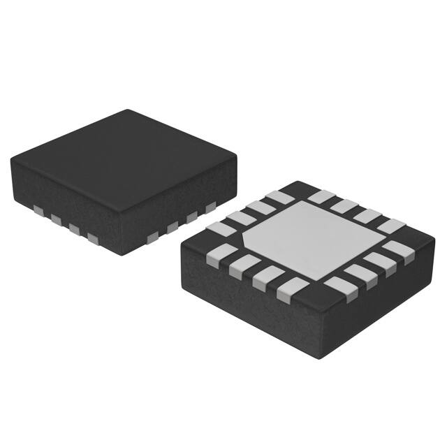
QFN16 3 x 3 mm
Multipurpose card status signal OFF
Non-inverted card reset pin RST driven by the
RSTIN input
Features
Complete smartcard interface
ISO 7816 and EMV™ 4.3 payment systems
compatible
One protected half-duplex bidirectional
buffered I/O line to the smartcard
5 V or 3 V (or 1.8 V in case of ST8034P)
selectable smartcard supply voltage (VCC).
Ensures controlled VCC rise and fall times and
provides smart overload detection with glitch
immunity.
Optional chip select function allows the device
interface to be isolated from the host
microcontroller signals - allows parallel
combination of the card interface devices
(ST8034C)
Card clock generation by integrated crystal
oscillator or from external clock source
October 2013
This is information on a product in full production.
Thermal and short-circuit protection of all card
contacts
Card presence detection contacts debounced
Enhanced card side ESD protection of 8 kV
Common SO16 3.9 x 9.9 mm body or a spacesaving QFN16 3 x 3 mm package
Temperature range -25 to +85 °C
Applications
Smartcard readers for
Set-top boxes
Pay-TV
Identification
Banking
Tachographs
DocID024587 Rev 4
1/40
www.st.com
1
�Contents
ST8034T, ST8034AT, ST8034P, ST8034C
Contents
1
Description . . . . . . . . . . . . . . . . . . . . . . . . . . . . . . . . . . . . . . . . . . . . . . . . . 6
2
Block diagrams . . . . . . . . . . . . . . . . . . . . . . . . . . . . . . . . . . . . . . . . . . . . . 7
3
Pin description . . . . . . . . . . . . . . . . . . . . . . . . . . . . . . . . . . . . . . . . . . . . 10
4
Maximum ratings . . . . . . . . . . . . . . . . . . . . . . . . . . . . . . . . . . . . . . . . . . . 13
5
Electrical characteristics . . . . . . . . . . . . . . . . . . . . . . . . . . . . . . . . . . . . 14
Electrical characteristics over recommended operating conditions . . . . . . . . . . . 14
6
Functional description . . . . . . . . . . . . . . . . . . . . . . . . . . . . . . . . . . . . . . 22
6.1
Power supplies . . . . . . . . . . . . . . . . . . . . . . . . . . . . . . . . . . . . . . . . . . . . . 22
6.2
Voltage supervisor . . . . . . . . . . . . . . . . . . . . . . . . . . . . . . . . . . . . . . . . . . 22
6.3
6.2.1
Voltage supervisor ST8034T and ST8034AT . . . . . . . . . . . . . . . . . . . . . 22
6.2.2
Voltage supervisor with PORADJ function (ST8034P and ST8034C) . . 23
Clock circuits . . . . . . . . . . . . . . . . . . . . . . . . . . . . . . . . . . . . . . . . . . . . . . 25
6.3.1
ST8034T and ST8034AT clock possibilities . . . . . . . . . . . . . . . . . . . . . . 25
6.3.2
ST8034P and ST8034C clock . . . . . . . . . . . . . . . . . . . . . . . . . . . . . . . . 26
6.4
Input and output circuits . . . . . . . . . . . . . . . . . . . . . . . . . . . . . . . . . . . . . . 26
6.5
Shutdown mode . . . . . . . . . . . . . . . . . . . . . . . . . . . . . . . . . . . . . . . . . . . . 26
6.6
Activation sequence . . . . . . . . . . . . . . . . . . . . . . . . . . . . . . . . . . . . . . . . . 27
6.7
Deactivation sequence . . . . . . . . . . . . . . . . . . . . . . . . . . . . . . . . . . . . . . . 28
6.8
VCC generator . . . . . . . . . . . . . . . . . . . . . . . . . . . . . . . . . . . . . . . . . . . . . 29
6.9
Fault detection . . . . . . . . . . . . . . . . . . . . . . . . . . . . . . . . . . . . . . . . . . . . . 29
6.10
Card supply voltage (VCC) selection . . . . . . . . . . . . . . . . . . . . . . . . . . . . 31
6.11
6.10.1
Automatic determining of card supply voltage (VCC) - all versions
except ST8034P . . . . . . . . . . . . . . . . . . . . . . . . . . . . . . . . . . . . . . . . . . 31
6.10.2
Card supply (VCC) selection by tristate VCC_SEL pin (ST8034P only) . 32
Chip select (ST8034C only) . . . . . . . . . . . . . . . . . . . . . . . . . . . . . . . . . . . 32
7
Package information . . . . . . . . . . . . . . . . . . . . . . . . . . . . . . . . . . . . . . . . 33
8
Tape and reel information . . . . . . . . . . . . . . . . . . . . . . . . . . . . . . . . . . . . 37
9
Revision history . . . . . . . . . . . . . . . . . . . . . . . . . . . . . . . . . . . . . . . . . . . 39
2/40
DocID024587 Rev 4
�List of tables
ST8034T, ST8034AT, ST8034P, ST8034C
List of tables
Table 1.
Table 2.
Table 3.
Table 4.
Table 5.
Table 6.
Table 7.
Table 8.
Table 9.
Table 10.
Table 11.
Table 12.
Table 13.
Table 14.
Table 15.
Table 16.
Table 17.
Table 18.
Table 19.
Table 20.
4/40
Device summary . . . . . . . . . . . . . . . . . . . . . . . . . . . . . . . . . . . . . . . . . . . . . . . . . . . . . . . . . . 6
Pin description ST8034T and ST8034AT . . . . . . . . . . . . . . . . . . . . . . . . . . . . . . . . . . . . . . 11
Pin description ST8034P and ST8034C . . . . . . . . . . . . . . . . . . . . . . . . . . . . . . . . . . . . . . . 12
Absolute maximum ratings, . . . . . . . . . . . . . . . . . . . . . . . . . . . . . . . . . . . . . . . . . . . . . . . . 13
Thermal data. . . . . . . . . . . . . . . . . . . . . . . . . . . . . . . . . . . . . . . . . . . . . . . . . . . . . . . . . . . . 13
Recommended operating conditions . . . . . . . . . . . . . . . . . . . . . . . . . . . . . . . . . . . . . . . . . 13
Supply voltages . . . . . . . . . . . . . . . . . . . . . . . . . . . . . . . . . . . . . . . . . . . . . . . . . . . . . . . . . 14
Card interface . . . . . . . . . . . . . . . . . . . . . . . . . . . . . . . . . . . . . . . . . . . . . . . . . . . . . . . . . . . 16
Microcontroller interface . . . . . . . . . . . . . . . . . . . . . . . . . . . . . . . . . . . . . . . . . . . . . . . . . . . 18
Clock circuits. . . . . . . . . . . . . . . . . . . . . . . . . . . . . . . . . . . . . . . . . . . . . . . . . . . . . . . . . . . . 20
Protection characteristics . . . . . . . . . . . . . . . . . . . . . . . . . . . . . . . . . . . . . . . . . . . . . . . . . . 21
Timing characteristics . . . . . . . . . . . . . . . . . . . . . . . . . . . . . . . . . . . . . . . . . . . . . . . . . . . . . 21
ST8034T and ST8034AT clock frequency selection. . . . . . . . . . . . . . . . . . . . . . . . . . . . . . 25
ST8034P VCC selection . . . . . . . . . . . . . . . . . . . . . . . . . . . . . . . . . . . . . . . . . . . . . . . . . . . 32
SO16 - 3.9 x 9.9 mm body package mechanical data . . . . . . . . . . . . . . . . . . . . . . . . . . . . 34
QFN16 - 3 x 3 x 0.8 mm, 0.5 mm pitch package mechanical data . . . . . . . . . . . . . . . . . . 36
Dimensions of carrier tape for SO16 - 3.9 x 9.9 mm. . . . . . . . . . . . . . . . . . . . . . . . . . . . . . 37
Dimensions of carrier tape for QFN16 - 3 x 3 x 0.55 mm . . . . . . . . . . . . . . . . . . . . . . . . . . 38
Tape and reel specification QFN16 . . . . . . . . . . . . . . . . . . . . . . . . . . . . . . . . . . . . . . . . . . 38
Document revision history . . . . . . . . . . . . . . . . . . . . . . . . . . . . . . . . . . . . . . . . . . . . . . . . . 39
DocID024587 Rev 4
�ST8034T, ST8034AT, ST8034P, ST8034C
List of figures
List of figures
Figure 1.
Figure 2.
Figure 3.
Figure 4.
Figure 5.
Figure 6.
Figure 7.
Figure 8.
Figure 9.
Figure 10.
Figure 11.
Figure 12.
Figure 13.
Figure 14.
Figure 15.
Figure 16.
Figure 17.
Figure 18.
Figure 19.
Figure 20.
Figure 21.
Figure 22.
Figure 23.
Figure 24.
Block diagram ST8034T and ST8034AT . . . . . . . . . . . . . . . . . . . . . . . . . . . . . . . . . . . . . . . 7
Block diagram ST8034P . . . . . . . . . . . . . . . . . . . . . . . . . . . . . . . . . . . . . . . . . . . . . . . . . . . . 8
Block diagram ST8034C . . . . . . . . . . . . . . . . . . . . . . . . . . . . . . . . . . . . . . . . . . . . . . . . . . . . 9
Pin connections ST8034T and ST8034AT, top view . . . . . . . . . . . . . . . . . . . . . . . . . . . . . 10
Pin connections ST8034P (options VCC_SEL and PORADJ pins),
top-through view . . . . . . . . . . . . . . . . . . . . . . . . . . . . . . . . . . . . . . . . . . . . . . . . . . . . . . . . . 10
Pin connections ST8034C (options chip select and PORADJ pins),
top-through view . . . . . . . . . . . . . . . . . . . . . . . . . . . . . . . . . . . . . . . . . . . . . . . . . . . . . . . . . 10
Definition of duty cycle and input and output rise/fall times . . . . . . . . . . . . . . . . . . . . . . . . 21
Voltage supervisor - ST8034T and ST8034AT . . . . . . . . . . . . . . . . . . . . . . . . . . . . . . . . . . 22
Voltage supervisor with adjustable VDD(INTF) threshold (PORADJ function)
- ST8034P and ST8034C . . . . . . . . . . . . . . . . . . . . . . . . . . . . . . . . . . . . . . . . . . . . . . . . . . 24
Voltage supervisor waveforms . . . . . . . . . . . . . . . . . . . . . . . . . . . . . . . . . . . . . . . . . . . . . . 24
External clock usage. . . . . . . . . . . . . . . . . . . . . . . . . . . . . . . . . . . . . . . . . . . . . . . . . . . . . . 25
Activation sequence . . . . . . . . . . . . . . . . . . . . . . . . . . . . . . . . . . . . . . . . . . . . . . . . . . . . . . 27
Deactivation sequence . . . . . . . . . . . . . . . . . . . . . . . . . . . . . . . . . . . . . . . . . . . . . . . . . . . . 28
Deactivation sequence after card removal . . . . . . . . . . . . . . . . . . . . . . . . . . . . . . . . . . . . . 30
Debounce at OFF, CMDVCC, PRES and VCC pins . . . . . . . . . . . . . . . . . . . . . . . . . . . . . . 30
Card activation to VCC = 5 V (tW_VCC > 30 ms) . . . . . . . . . . . . . . . . . . . . . . . . . . . . . . . . . 31
Card activation to VCC = 3 V (tW_VCC < 15 ms) . . . . . . . . . . . . . . . . . . . . . . . . . . . . . . . . . 31
Card activation to VCC = 3 V, tW_VCC >15 ms. . . . . . . . . . . . . . . . . . . . . . . . . . . . . . . . . . . 32
SO16 - 3.9 x 9.9 mm body package outline . . . . . . . . . . . . . . . . . . . . . . . . . . . . . . . . . . . . 33
Recommended footprint SO16 - 3.9 x 9.9 mm body . . . . . . . . . . . . . . . . . . . . . . . . . . . . . 34
QFN16 - 3 x 3 x 0.8 mm, 0.5 mm pitch package outline. . . . . . . . . . . . . . . . . . . . . . . . . . . 35
Recommended footprint QFN16 - 3 x 3 x 0.8 mm, 0.5 mm pitch . . . . . . . . . . . . . . . . . . . . 36
Carrier tape for SO16 - 3.9 x 9.9 mm . . . . . . . . . . . . . . . . . . . . . . . . . . . . . . . . . . . . . . . . . 37
Carrier tape for QFN16 - 3 x 3 x 0.55 mm . . . . . . . . . . . . . . . . . . . . . . . . . . . . . . . . . . . . . 38
DocID024587 Rev 4
5/40
�Description
1
ST8034T, ST8034AT, ST8034P, ST8034C
Description
The ST8034T/ST8034AT/ST8034P/ST8034C devices are complete low-cost analog
interfaces for asynchronous and synchronous smartcards operating at a supply voltage
of 5 V or 3 V (or even 1.8 V in the case of ST8034P).
The ST8034T/ST8034AT/ST8034P/ST8034C devices can be placed between the card and
the microcontroller to provide all supply, protection, detection and control functions, with just
a few external components.
Table 1. Device summary
External
Order code PORADJ CLKDIV CLKIN
crystal
VCC
selection Chip
pin
select
5/3.0/1.8 V
Package
Shipment
Package
topmark
ST8034TDT
SO16
Tape and
(3.9 x 9.9 mm)
reel
ST8034ATDT
SO16
Tape and
ST8034ATDT
(3.9 x 9.9 mm)
reel
ST8034PQR
ST8034CQR
6/40
DocID024587 Rev 4
ST8034TDT
QFN16
(3 x 3 mm)
Tape and
reel
034P
QFN16
(3 x 3 mm)
Tape and
reel
034C
�ST8034T, ST8034AT, ST8034P, ST8034C
2
Block diagrams
Block diagrams
Figure 1. Block diagram ST8034T and ST8034AT
����Q)
9''
��
����Q)
*1'
9''3
�
��
6833/<
,17(51$/��
5()(5(1&(
92/7$*(�
6(16(
35(6
,17(51$/��
26&,//$725
&/.83
$/$50
(1�
�
39&&
9&&�/'2
�� 9&&
����Q)
567,1
&0'9&&
2))
&/.',9
�
6(48(1&(5
�
5(6(7�
*(1(5$725
�� 567
��
�
(1�
/(9(/
6+,)7(5
,�28&
(1�
����Q)
&/2&.�
&,5&8,75<
&/.
(1�
�� &/.
&/2&.�
*(1(5$725
&$5'�
&211(&725
&0'9&&�
'(7(&7,21
��
7+(50$/�
3527(&7,21
,�2
75$16&(,9(5
&5 device is active, low =>
all microcontroller interface pins set to high impedance.
(ST8034C)
VCC_SEL
VDD(INTF)
VCC (card supply) selection input: logic high selects
VCC = 5 V, logic low selects VCC = 3 V, left-floating
selects VCC = 1.8 V. (ST8034P)
4
CMDVCC
VDD(INTF)
Start activation sequence input (from microcontroller,
active low)
5
PRES
VDD(INTF)
Card presence input (active low: PRES = low => card is
present). Debounced.
6
I/O
VCC
7
GND
8
CLK
VCC
Clock to card (C3)
9
RST
VCC
Card reset, output (C2)
10
VCC
Supply voltage for the card, output (C1)
11
VDDP
LDO supply voltage input (for VCC generation)
12
VDD
Control logic supply voltage input
13
PORADJ
VDD(INTF)
Power-on reset threshold adjustment input
14
OFF
VDD(INTF)
Interrupt to microcontroller (active low output, with
internal 20 k pull-up resistor to VDD(INTF))
15
I/OUC
VDD(INTF)
Microcontroller data I/O line (with internal 10 k pull-up
resistor connected to VDD(INTF))
16
CLKIN
VDD(INTF)
External clock input
Microcontroller interface supply voltage (input)
Card input/output data line (C7); with internal 9 k
pull-up resistor to VCC
Ground
DocID024587 Rev 4
�ST8034T, ST8034AT, ST8034P, ST8034C
4
Maximum ratings
Maximum ratings
Table 4. Absolute maximum ratings(1), (2)
Symbol
Parameter
Min.
Max.
Unit
VDD
Supply voltage, logic
-0.3
6
V
VDDP
Supply voltage, power
-0.3
6
V
Supply voltage, interface
-0.3
6
V
Input voltage on XTAL1, XTAL2, RSTIN, I/OUC,
CLKDIV, CS, VCC_SEL, CLKIN, PORADJ,
CMDVCC, OFF, PRES, and I/O pins
-0.3
6
V
Human body model (HBM) on card lines - I/O, RST,
VCC, CLK, and PRES pins
-8
8
kV
Human body model (HBM), all other pins
-2
2
kV
Machine model (MM), all pins
-200
200
V
VESD (FCDM)
Field charged device model (FCDM), all pins
-500
500
V
PTOT
Total power dissipation (TA = -25 to +85 °C)
0.25
W
Maximum operating junction temperature
125
°C
150
°C
VDD(INTF)
VIN
VESD (HBM)
VESD (MM)
TJ(MAX)
TSTG
Storage temperature range
-55
1. Absolute maximum ratings are those values beyond which damage to the device may occur. Functional
operation under these conditions is not implied.
2. All card contacts are protected against short-circuit to any other card contact.
Table 5. Thermal data
Symbol
RTHJA
Parameter
Thermal resistance junction-ambient temperature
(multilayer test board - JEDEC standard)
Test
conditions
Typ.
Unit
SO16
87
°C/W
QFN16
60
°C/W
Min.
Max.
Unit
-25
85
°C
Table 6. Recommended operating conditions
Symbol
TA
Parameter
Test conditions
Ambient temperature range
DocID024587 Rev 4
13/40
�Electrical characteristics
5
ST8034T, ST8034AT, ST8034P, ST8034C
Electrical characteristics
Electrical characteristics over recommended operating conditions
Table 7. Supply voltages
Symbol
Test conditions(1)
Parameter
Min.
Typ.
Max.
Unit
2.7
3.3
5.5(2)
V
4.85
5
5.5
3
3.3
5.5
1.6
3.3
VDD
+0.3(3)
V
Shutdown mode
35
A
Active mode
2
mA
Shutdown mode, fXTAL stopped
5
A
Device supply voltages
VDD
Supply voltage, logic
VDDP
Supply voltage, power
VDD(INTF)
IDD
IDDP
IDD(INTF)
VCC = 5 V
VCC = 3 V or 1.8 V
Supply voltage,
microcontroller interface
Supply current, logic
Supply current, power
Supply current, interface
V
Active mode, fCLK = fXTAL/2, no ICC load
1.5
Active mode, fCLK = fXTAL/2,
ICC = 65 mA
70
Shutdown mode
6
A
Shutdown mode, ST8034P only
45
A
mA
Card supply voltage
VCC
ICC
CVCC
SR
VCC(SHDN)
14/40
Card supply voltage
(output)(4)
Card supply current (refer
also to Table 11: Protection
characteristics on page 21)
Active mode, VCC = 5 V, ICC < 65 mA
4.75
5.0
5.25
With current pulses of 40 nAs at
ICC < 200 mA, t < 400 ns(4)
4.65
5.0
5.25
Active mode, VCC = 3 V, ICC < 65 mA
2.85
3.05
3.15
With current pulses of 40 nAs at
ICC < 200 mA, t < 400 ns(4)
2.76
Active mode, VCC = 1.8 V, ICC < 65 mA
1.71
With current pulses of 15 nAs at
ICC < 200 mA, t < 400 ns(4)
1.66
VCC output voltage in
shutdown mode
1.83
VCC shorted to GND
1.89
65
90
120
150
160
320
530
VCC = 5 V
0.055
0.180
0.300
VCC = 3 V
0.040
0.180
0.300
VCC = 1.8 V
0.025
0.180
0.300
No load
-0.1
0.1
ICC = 1 mA
-0.1
0.3
DocID024587 Rev 4
V
1.94
VCC = 5 V, 3 V or 1.8 V
VCC decoupling capacitor(5) VCC to GND
VCC slew rate (rising and
falling)(5)
3.20
mA
nF
V/s
V
�ST8034T, ST8034AT, ST8034P, ST8034C
Electrical characteristics
Table 7. Supply voltages (continued)
Symbol
ICC(SHDN)
Test conditions(1)
Parameter
VCC output current in
shutdown mode
Min.
Typ.
VCC connected to GND
CMDVCC pulse width for
tW_VCC(5V) VCC = 5 V, all versions
except ST8034P
See section Section 6.10.1 on page 31
CMDVCC pulse width for
tW_VCC(3V) VCC = 3 V, all versions
except ST8034P
See section Section 6.10.1 on page 31
Max.
Unit
-1
mA
30
ms
15
ms
Device supply voltages monitoring
VTH
VHYS
Falling supply voltage
threshold
Hysteresis on supply
voltage threshold
VDD pin
2.3
2.4
2.5
VDDP pin (VCC = 5 V)
3.0
4.1
4.4
VDDP pin (VCC = 3 V or 1.8 V)
2.3
2.4
2.5
VDD(INTF) pin (ST8034T, ST8034AT)
1.20
1.24
1.29
PORADJ pin (ST8034P, ST8034C)
1.20
1.24
1.29
VDD pin
50
100
150
VDDP pin (VCC = 5 V)
100
200
350
VDDP pin (VCC = 3 V or 1.8 V)
50
100
150
VDD(INTF) pin (ST8034T, ST8034AT)
10
20
30
PORADJ pin (ST8034P, ST8034C)
10
20
30
II(PORADJ) Input current, PORADJ pin
tW
-1
Power-on or undervoltage
reset pulse width (minimum)
5.1
8
V
mV
1
A
10.2
ms
1. TA = 25 °C, VDD = 3.3 V, VDDP = 5 V, VDD(INTF) = 3.3 V, fXTAL = 10 MHz, unless otherwise noted.
2. The device can operate at VDD supply voltage up to 5.5 V, however the specified parameters (mainly related to current
consumption and input currents) are guaranteed in the basic VDD range 2.7 to 3.6 V.
3. The device can operate at VDD(INTF) supply voltage up to 5.5 V, however the specified parameters (mainly related to current
consumption) are guaranteed in the basic VDD(INTF) range 1.6 to 3.6 V.
4. These current pulses are filtered by the decoupling capacitors on the VCC pin, therefore for the LDO just the mean value
matters.
5. Two low ESR (< 350 m) ceramic capacitors for VCC decoupling recommended: 100 nF ± 20% (up to
330 nF ± 20%) close to the ST8034 and 100 nF ± 20% (up to 330 nF ± 20%) close to the card.
DocID024587 Rev 4
15/40
�Electrical characteristics
ST8034T, ST8034AT, ST8034P, ST8034C
Table 8. Card interface
Symbol
Parameter
Test conditions(1)
Min.
Typ.
Max.
Unit
200
ns
400
ns
Data line to the card (I/O pin)(2)
tD
tW(PU)
Delay time
Falling edge on pin I/O to
falling edge on I/OUC or vice
versa
Pull-up pulse width
100
fIO
Input/output frequency
1
MHz
CI
Input capacitance
10
pF
VO
Output voltage in shutdown
mode
IO
Output current in shutdown
mode
VOL
Output voltage low
No load
0
0.1
V
IO = 1 mA
0
0.3
V
-1
mA
I/O connected to GND
IOL = 1 mA
0
0.3
VCC - 0.4
VCC
0.9 VCC
VCC + 0.1
IOH < -40 A (VCC = 5 V or 3 V) 0.75 VCC
VCC + 0.1
IOH < -20 A (VCC = 1.8 V)
0.75 VCC
VCC + 0.1
IOH -15 mA (current limit)
0
0.4
-0.3
0.8
VCC = 5 V
0.6 VCC
VCC + 0.3
VCC = 3 V
0.7 VCC
VCC + 0.3
IOL 15 mA (current limit)
No load
VOH
Output voltage high
VIL
Input voltage low
VIH
Input voltage high
V
V
V
Hysteresis
I/O pin
IIL
Input current low
I/O pin, VIL = 0 V
750
A
IIH
Input current high
I/O pin, VIH = VCC
10
A
tR(I)
Input rise time
VIL max. to VIH min.
0.15
s
tR(O)
Output rise time
CL 80 pF, 10% to 90%,
0 V to VCC
0.1
s
tF(I)
Input fall time
VIL max. to VIH min.
0.15
s
tF(O)
Output fall time
CL 80 pF, 10% to 90%,
0 V to VCC
0.1
s
RPU
Pull-up resistance to VCC
IPU
Pull-up current (one-shot
circuit active)
VHYS
50
V
mV
7
9
11
k
VOH = 0.9 VCC
-8
-6
-4
mA
No load
0
0.1
IO = 1 mA
0
0.3
Reset output to the card (RST pin)
VO
Output voltage in shutdown
mode
IO
Output current in shutdown
mode
16/40
RST connected to GND
DocID024587 Rev 4
-1
V
mA
�ST8034T, ST8034AT, ST8034P, ST8034C
Electrical characteristics
Table 8. Card interface (continued)
Symbol
tD
VOL
Test conditions(1)
Parameter
Delay time
Output voltage low
Output voltage high
Typ.
Between RSTIN and RST; RST
enabled
Max.
Unit
2
s
IOL = 200 A, VCC = 5 V
0
0.3
IOL = 200 A, VCC = 3 V
0
0.2
VCC - 0.4
VCC
0.9 VCC
VCC
0
0.4
IOL = 20 mA (current limit)
VOH
Min.
IOH = -200 A
IOH = -20 mA (current limit)
V
V
tR
Rise time
CL = 100 pF
0.1
s
tF
Fall time
CL = 100 pF
0.1
s
Clock output to the card (CLK pin)
VO
Output voltage in shutdown
mode
IO
Output current in shutdown
mode
VOL
Output voltage low
VOH
Output voltage high
tR
tF
Rise time(3)
Fall
time(3)
No load
0
0.1
IO = 1 mA
0
0.3
CLK connected to GND
IOL = 200 A
-1
0
0.3
IOL = 70 mA (current limit)
VCC -0.4
VCC
IOH = -200 A
0.9 VCC
VCC
0
0.4
IOH = -70 mA (current limit)
V
mA
V
V
CL = 30 pF
16
ns
CL = 30 pF
16
ns
fCLK
Frequency on CLK pin
Operational
0
26
MHz
DC
Duty cycle(3)
CL = 30 pF
45
55
%
SR
Slew rate (rise and fall,
CL = 30 pF)
VCC = 5 V
0.2
VCC = 3 V
0.12
V/ns
Card detection input (PRES pin)(4)
VIL
Input voltage low
-0.3
0.3
VDD(INTF)
V
VIH
Input voltage high
0.7
VDD(INTF)
VDD(INTF)
+ 0.3
V
VHYS
0.14
VDD(INTF)
Hysteresis
V
IIL
Input current low
0 < VIL < VDD(INTF)
5
A
IIH
Input current high
0 < VIH < VDD(INTF)
5
A
1. TA = 25 °C, VDD = 3.3 V, VDDP = 5 V, VDD(INTF) = 3.3 V, fXTAL = 10 MHz, unless otherwise noted.
2. With an internal 9 k pull-up resistor to VCC.
3. For rise and fall times and duty cycle definitions, see Figure 7 on page 21.
4. PRES is active low, with an internal current source of 1.25 A to VDD(INTF).
DocID024587 Rev 4
17/40
�Electrical characteristics
ST8034T, ST8034AT, ST8034P, ST8034C
Table 9. Microcontroller interface
Symbol
Test conditions(1)
Parameter
Min.
Typ.
Max.
Unit
200
ns
400
ns
Data line to the microcontroller (I/OUC pin)(2)
tD
tW(PU)
Delay time
Falling edge on pin I/O to
falling edge on I/OUC or vice
versa
Pull-up pulse width
100
fIO
Input/output frequency
1
MHz
CI
Input capacitance
10
pF
VOL
Output voltage low
0
0.3
V
No load
0.9
VDD(INTF)
VDD(INTF)
+ 0.1
IOH 40 A, VDD(INTF) > 2 V
0.75
VDD(INTF)
VDD(INTF)
+ 0.1
IOH 20 A, VDD(INTF) < 2 V
0.75
VDD(INTF)
VDD(INTF)
+ 0.1
VOH
Output voltage high
IOL = 1 mA
V
VIL
Input voltage low
-0.3
0.3
VDD(INTF)
V
VIH
Input voltage high
0.7
VDD(INTF)
VDD(INTF)
+ 0.3
V
VHYS
0.14
VDD(INTF)
Hysteresis
I/OUC pin
V
IIL
Input current low
VIL = 0 V
500
A
IIH
Input current high
VIH = VDD(INTF)
10
A
12
k
RPU
Pull-up resistance to
VDD(INTF)
IPU
Pull-up current (one-shot
circuit active)
VOH = 0.9 VDD(INTF)
tR(I)
Input rise time
VIL max. to VIH min.
0.15
s
tR(O)
Output rise time
CL 30 pF, 10% to 90%,
0 V to VDD(INTF)
0.1
s
tF(I)
Input fall time
VIL max. to VIH min.
0.15
s
tF(O)
Output fall time
CL 30 pF, 10% to 90%,
0 V to VDD(INTF)
0.1
s
8
10
-1
mA
Device control inputs (CLKDIV, RSTIN, VCC_SEL, CS pins)(3)
VIL
Input voltage low
-0.3
0.3
VDD(INTF)
V
VIH
Input voltage high
0.7
VDD(INTF)
VDD(INTF)
+ 0.3
V
VHYS
18/40
0.14
VDD(INTF)
Hysteresis
DocID024587 Rev 4
V
�ST8034T, ST8034AT, ST8034P, ST8034C
Electrical characteristics
Table 9. Microcontroller interface (continued)
Symbol
Test conditions(1)
Parameter
Min.
Typ.
Max.
Unit
IIL
Input current low
1
A
IIH
Input current high
1
A
VIL(VCC_SEL) Input voltage low
ST8034P only. The
low/floating threshold is
subject to minor variations.
-0.3
0.3
VDD(INTF)
V
VIH(VCC_SEL) Input voltage high
ST8034P only. The
floating/high threshold is
subject to minor variations.
0.7
VDD(INTF)
VDD(INTF)
+0.3
V
IIL(VCC_SEL) Input current low
ST8034P only
IIH(VCC_SEL) Input current high
ST8034P only
Device control input
A
-30
30
A
CMDVCC(4)
VIL
Input voltage low
-0.3
0.3
VDD(INTF)
V
VIH
Input voltage high
0.7
VDD(INTF)
VDD(INTF)
+ 0.3
V
VHYS
0.14
VDD(INTF)
Hysteresis
V
IIL
Input current low
VIL = 0 V
1
A
IIH
Input current high
VIH = VDD(INTF)
1
A
100
Hz
0.3
V
fCMDVCC
Frequency at CMDVCC
pin
OFF output(5)
VOL
Output voltage low
IOL = 2 mA
VOH
Output voltage high
IOH = -15 A
RPU
Pull-up resistance to
VDD(INTF)
0
0.75
VDD(INTF)
16
V
20
24
k
1. TA = 25 °C, VDD = 3.3 V, VDDP = 5 V, VDD(INTF) = 3.3 V, fXTAL = 10 MHz, unless otherwise noted.
2. With an internal 10 k pull-up resistor to VDD(INTF).
3. For clock frequency division control (CLKDIV), see Table 13 on page 25.
4. CMDVCC is active low.
5. OFF is an NMOS open drain, with an internal 20 k pull-up resistor to VDD(INTF).
DocID024587 Rev 4
19/40
�Electrical characteristics
ST8034T, ST8034AT, ST8034P, ST8034C
Table 10. Clock circuits
Symbol
Parameter
Test conditions(1)
Min.
Typ.
Max.
Unit
Input for external clock (CLKIN pin - ST8034P, ST8034C)
VIL
Input voltage low
-0.3
0.3
VDD(INTF)
V
VIH
Input voltage high
0.7
VDD(INTF)
VDD(INTF)
+ 0.3
V
IIL
Input current low
VIL = 0 V
1
A
IIH
Input current high
VIH = VDD(INTF)
1
A
tR(I)
Input rise time
VIL max. to VIH min.
10
ns
tF(I)
Input fall time
VIL max. to VIH min.
10
ns
External clock frequency
External clock on CLKIN pin
26
MHz
fCLKIN
0.032
Internal oscillator
fOSC(INT)LOW
fOSC(INT)
Internal oscillator frequency
Shutdown mode
Active state
100
150
200
kHz
2
2.7
3.2
MHz
15
pF
2
26
MHz
0.032
26
MHz
Crystal oscillator (XTAL1 and XTAL2 pins)
CEXT
External capacitances
XTAL1 and XTAL2 to GND
(according to the crystal or
resonator specification)
fXTAL
External crystal frequency
Card clock reference, crystal
oscillator
fEXT
External clock frequency
External clock on XTAL1
tR(fEXT)
External clock frequency rise
time
External clock on XTAL1
10
ns
tF(fEXT)
External clock frequency fall
time
External clock on XTAL1
10
ns
VIL
Input voltage low
Crystal oscillator
-0.3
0.3 VDD
External clock on XTAL1
-0.3
0.3
VDD(INTF)
0.7 VDD
VDD +
0.3
Crystal oscillator
VIH
Input voltage high
External clock on XTAL1
0.7
VDD(INTF)
1. TA = 25 °C, VDD = 3.3 V, VDDP = 5 V, VDD(INTF) = 3.3 V, fXTAL = 10 MHz, unless otherwise noted.
20/40
DocID024587 Rev 4
VDD(INTF)
+ 0.3
V
V
�ST8034T, ST8034AT, ST8034P, ST8034C
Electrical characteristics
Table 11. Protection characteristics
Symbol
IOLIM
ISD(VCC)
TSD
Test conditions(1)
Parameter
Output current limit
(2)
Limit and shutdown card supply current
Min.
Typ.
Max.
I/O pin
-15
15
CLK pin
-70
70
RST pin
-20
20
VCC pin
90
Shutdown junction temperature
120
150
150
Unit
mA
mA
°C
1. TA = 25 °C, VDD = 3.3 V, VDDP = 5 V, VDD(INTF) = 3.3 V, fXTAL = 10 MHz, unless otherwise noted.
2. All card contacts are protected against short-circuit to any other card contact.
Table 12. Timing characteristics
Symbol
tACT
tDEACT
tD(START),
tD(END)
Test conditions(1)
Parameter
Activation time
See Figure 12 on
page 27
2090
Deactivation time
See Figure 13 on
page 28
35
tD(START) = t3,
see Figure 12 on
Delay time, CLK sent to card using an external page 27
clock
=t ,
t
D(END)
5
see Figure 12 on
page 27
tDEB
Min.
Debounce time
Typ.
90
2090
Max.
Unit
4160
µs
250
µs
4112
µs
2120
PRES pin
3.2
4160
4.5
6.4
ms
1. TA = 25 °C, VDD = 3.3 V, VDDP = 5 V, VDD(INTF) = 3.3 V, fXTAL = 10 MHz, unless otherwise noted.
Figure 7. Definition of duty cycle and input and output rise/fall times
W5
W)
���
92+
���
�92+���92/�����
���
���
W�
W�
92/
$0�����
Duty cycle (DC) = t1 / (t1 + t2).
DocID024587 Rev 4
21/40
�Functional description
6
ST8034T, ST8034AT, ST8034P, ST8034C
Functional description
Throughout this document it is assumed that the reader is familiar with ISO7816
terminology.
6.1
Power supplies
All interface signals to the host microcontroller are referenced to VDD(INTF). All card contacts
remain inactive during power-up or power-down. After powering-up the device, OFF output
remains low until CMDVCC input is set high and PRES input is low. During power-down,
OFF output goes low when VDDP falls below the VDDP falling threshold voltage. The internal
oscillator clock frequency fOSC(INT) is used only during the activation sequence. When the
card is not activated (CMDVCC input is high), the internal oscillator is in low frequency
mode to reduce power consumption.
Power-on sequence: supply voltages may be applied to the ST8034 in any sequence.
6.2
Voltage supervisor
6.2.1
Voltage supervisor ST8034T and ST8034AT
Figure 8. Voltage supervisor - ST8034T and ST8034AT
9''�,17)�
�
�
9''
9''
5()(5(1&(
92/7$*(
�
�
9''3
�
�
$0�����9�
22/40
DocID024587 Rev 4
�ST8034T, ST8034AT, ST8034P, ST8034C
Functional description
The voltage supervisor monitors the voltage of the VDD, VDDP and VDD(INTF) supplies and
provides both power-on reset (POR) and supply dropout detection during a card session.
The supervisor threshold voltages for VDD, VDDP and VDD(INTF) are set internally. As long as
VDD, VDDP or VDD(INTF) is less than the corresponding VTH + VHYS, the ST8034 device
remains inactive irrespective of the command line levels. After VDD, VDDP, and VDD(INTF)
have reached a level higher than the corresponding VTH + VHYS, the device still remains
inactive for the duration of tW, a defined reset pulse of approximately 8 ms
(tW = 1024 x 1/fOSC(INT)LOW) when the output of the supervisor keeps the control logic in
reset state. This is used to maintain the device in shutdown mode during the supply voltage
power-on, see Figure 10. A deactivation sequence is performed when either VDD, VDDP or
VDD(INTF) falls below the corresponding VTH.
6.2.2
Voltage supervisor with PORADJ function (ST8034P and ST8034C)
In the case of devices with the PORADJ pin (ST8034P, ST8034C), additional flexibility of the
voltage monitoring is available: the PORADJ pin provides an independent voltage
monitoring input that can be used for VDD(INTF) monitoring (as shown in Figure 9) or
generally for the monitoring of any external voltage to which the resistor divider is
connected, with adjustable threshold.
Undervoltage (UVLO) threshold adjustment on the PORADJ input with the resistor divider:
VDD(INTF) UVLO threshold (falling) = (R1+R2)/R2 x VTH(PORADJ)
VDD(INTF) UVLO threshold (rising) = (R1+R2)/R2 x (VTH(PORADJ) + VHYST(PORADJ))
If the external resistor divider is not used, connect the PORADJ pin to VDD(INTF), then
VDD(INTF) UVLO threshold = VTH(PORADJ).
DocID024587 Rev 4
23/40
�Functional description
ST8034T, ST8034AT, ST8034P, ST8034C
Figure 9. Voltage supervisor with adjustable VDD(INTF) threshold (PORADJ function)
- ST8034P and ST8034C
9''�,17)�
9''�,17)�
5�
325$'-
�
�
9''
5�
9''
5()(5(1&(
92/7$*(
�
�
9''3
�
�
$0�����9�
Figure 10. Voltage supervisor waveforms
97+���9+


 工商网监
湘ICP备2023018690号
工商网监
湘ICP备2023018690号

