STA321
4-channel digital audio system with FFX™ driver
Features
High efficiency FFX™ class-D modulator
100-dB dynamic range
Two stereo channels with I2S input/output data
interface
16-bit stereo ADC input with PGA and
microphone biasing
Analog and digital muxing/mixing capability
4-channel input sample rate converter
(8 kHz to 192 kHz)
Four channels of 24-bit audio processing
Flexible channel mapping and routing
Output configurations:
– 2.0
– 2.1
– 4.0
– Mono
Embedded CMOS bridge: up to 0.5 W/channel
pfStart™ for pop-free single-ended operations
Play and record simultaneous operation
Pre and post mix stages
Individual channel and master gain/attenuation
Table 1.
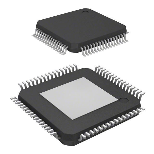
LQFP-64 package
with exposed pad down (EPD)
Digital gain/attenuation -105 dB to +36 dB in
0.5-dB steps
Soft volume update and muting
DC-blocking selectable high-pass filter
Selectable de-emphasis filter
Up to 13 28-bit user programmable biquads
(EQ) per channel
Bass/treble tone control
Ternary, binary or phase shift modulation
PWM output
Headphone output with jack detector
I2C control.
Device summary
Order code
Temperature range
Package
Packaging
STA321
0 to 70 °C
LQFP-64 EPD
Tray
STA321TR
0 to 70 °C
LQFP-64 EPD
Tape and reel
October 2009
Doc ID 15351 Rev 3
1/157
www.st.com
1
�Contents
STA321
Contents
1
Overview . . . . . . . . . . . . . . . . . . . . . . . . . . . . . . . . . . . . . . . . . . . . . . . . . . 9
2
Pin description . . . . . . . . . . . . . . . . . . . . . . . . . . . . . . . . . . . . . . . . . . . . 10
3
Electrical specifications . . . . . . . . . . . . . . . . . . . . . . . . . . . . . . . . . . . . . 13
4
3.1
Absolute maximum ratings . . . . . . . . . . . . . . . . . . . . . . . . . . . . . . . . . . . . 13
3.2
Recommended operating conditions . . . . . . . . . . . . . . . . . . . . . . . . . . . . 13
3.3
Electrical characteristics . . . . . . . . . . . . . . . . . . . . . . . . . . . . . . . . . . . . . . 14
3.4
Embedded crystal oscillator . . . . . . . . . . . . . . . . . . . . . . . . . . . . . . . . . . . 17
3.5
Embedded DC regulator . . . . . . . . . . . . . . . . . . . . . . . . . . . . . . . . . . . . . . 19
Power-up and power-down sequences . . . . . . . . . . . . . . . . . . . . . . . . . 20
4.1
Device power-up . . . . . . . . . . . . . . . . . . . . . . . . . . . . . . . . . . . . . . . . . . . . 20
4.2
Software power-down mode . . . . . . . . . . . . . . . . . . . . . . . . . . . . . . . . . . . 21
4.2.1
4.3
5
Hardware power-down mode . . . . . . . . . . . . . . . . . . . . . . . . . . . . . . . . . . 23
4.3.1
Mild power-down . . . . . . . . . . . . . . . . . . . . . . . . . . . . . . . . . . . . . . . . . . 25
4.3.2
Full power-down . . . . . . . . . . . . . . . . . . . . . . . . . . . . . . . . . . . . . . . . . . . 27
Clock management . . . . . . . . . . . . . . . . . . . . . . . . . . . . . . . . . . . . . . . . . 29
5.1
System clock . . . . . . . . . . . . . . . . . . . . . . . . . . . . . . . . . . . . . . . . . . . . . . 30
5.1.1
6
Configuration example . . . . . . . . . . . . . . . . . . . . . . . . . . . . . . . . . . . . . . 30
5.2
Peripheral clock manager . . . . . . . . . . . . . . . . . . . . . . . . . . . . . . . . . . . . . 31
5.3
Fractional PLL . . . . . . . . . . . . . . . . . . . . . . . . . . . . . . . . . . . . . . . . . . . . . 31
5.3.1
PLL block description . . . . . . . . . . . . . . . . . . . . . . . . . . . . . . . . . . . . . . . 31
5.3.2
Output frequency computation . . . . . . . . . . . . . . . . . . . . . . . . . . . . . . . . 32
Digital processing stage . . . . . . . . . . . . . . . . . . . . . . . . . . . . . . . . . . . . . 34
6.1
Signal processing flow . . . . . . . . . . . . . . . . . . . . . . . . . . . . . . . . . . . . . . . 34
6.2
Sampling rate converter . . . . . . . . . . . . . . . . . . . . . . . . . . . . . . . . . . . . . . 35
6.3
Pre-EQ mix 1 and post-EQ mix . . . . . . . . . . . . . . . . . . . . . . . . . . . . . . . . 36
6.3.1
6.4
2/157
Configuration example . . . . . . . . . . . . . . . . . . . . . . . . . . . . . . . . . . . . . . 22
Presets . . . . . . . . . . . . . . . . . . . . . . . . . . . . . . . . . . . . . . . . . . . . . . . . . . 37
Pre scaler . . . . . . . . . . . . . . . . . . . . . . . . . . . . . . . . . . . . . . . . . . . . . . . . . 37
Doc ID 15351 Rev 3
�STA321
Contents
6.4.1
6.5
Equalization, tone control and effects . . . . . . . . . . . . . . . . . . . . . . . . . . . 37
6.6
Biquads . . . . . . . . . . . . . . . . . . . . . . . . . . . . . . . . . . . . . . . . . . . . . . . . . . 39
6.6.1
Presets . . . . . . . . . . . . . . . . . . . . . . . . . . . . . . . . . . . . . . . . . . . . . . . . . . 39
6.7
High-pass filter . . . . . . . . . . . . . . . . . . . . . . . . . . . . . . . . . . . . . . . . . . . . . 39
6.8
Deemphasis filter . . . . . . . . . . . . . . . . . . . . . . . . . . . . . . . . . . . . . . . . . . . 40
6.9
Bass and treble control . . . . . . . . . . . . . . . . . . . . . . . . . . . . . . . . . . . . . . . 41
6.9.1
6.10
Configuration example . . . . . . . . . . . . . . . . . . . . . . . . . . . . . . . . . . . . . . 42
Programmable delay . . . . . . . . . . . . . . . . . . . . . . . . . . . . . . . . . . . . . . . . 42
6.10.1
7
Presets . . . . . . . . . . . . . . . . . . . . . . . . . . . . . . . . . . . . . . . . . . . . . . . . . . 37
Presets . . . . . . . . . . . . . . . . . . . . . . . . . . . . . . . . . . . . . . . . . . . . . . . . . . 42
6.11
Volume and mute control . . . . . . . . . . . . . . . . . . . . . . . . . . . . . . . . . . . . . 42
6.12
Limiter (clamping) . . . . . . . . . . . . . . . . . . . . . . . . . . . . . . . . . . . . . . . . . . . 43
6.13
FFX channel re-mapping . . . . . . . . . . . . . . . . . . . . . . . . . . . . . . . . . . . . . 43
6.14
Memory programming . . . . . . . . . . . . . . . . . . . . . . . . . . . . . . . . . . . . . . . 44
6.14.1
Writing one coefficient/location to RAM . . . . . . . . . . . . . . . . . . . . . . . . . 44
6.14.2
Writing a set of five coefficients/locations to RAM . . . . . . . . . . . . . . . . . 45
6.14.3
Reading a set of five coefficients/locations from RAM . . . . . . . . . . . . . . 46
6.14.4
RAM mapping . . . . . . . . . . . . . . . . . . . . . . . . . . . . . . . . . . . . . . . . . . . . 47
FFX . . . . . . . . . . . . . . . . . . . . . . . . . . . . . . . . . . . . . . . . . . . . . . . . . . . . . . 52
7.1
Functional description . . . . . . . . . . . . . . . . . . . . . . . . . . . . . . . . . . . . . . . 52
7.2
Modulation schemes . . . . . . . . . . . . . . . . . . . . . . . . . . . . . . . . . . . . . . . . 52
7.3
PWM shift feature . . . . . . . . . . . . . . . . . . . . . . . . . . . . . . . . . . . . . . . . . . . 55
7.4
Ternary mode . . . . . . . . . . . . . . . . . . . . . . . . . . . . . . . . . . . . . . . . . . . . . . 56
7.5
Minimum pulse limitation . . . . . . . . . . . . . . . . . . . . . . . . . . . . . . . . . . . . . 56
7.6
Headphone modulation . . . . . . . . . . . . . . . . . . . . . . . . . . . . . . . . . . . . . . 57
7.7
pfStart™ operation . . . . . . . . . . . . . . . . . . . . . . . . . . . . . . . . . . . . . . . . . . 58
7.8
PWM00 output . . . . . . . . . . . . . . . . . . . . . . . . . . . . . . . . . . . . . . . . . . . . . 59
8
CMOS power stage . . . . . . . . . . . . . . . . . . . . . . . . . . . . . . . . . . . . . . . . . 60
9
Fault detection and recovery . . . . . . . . . . . . . . . . . . . . . . . . . . . . . . . . . 63
9.1
External amplifier . . . . . . . . . . . . . . . . . . . . . . . . . . . . . . . . . . . . . . . . . . . 63
9.2
CMOS bridge . . . . . . . . . . . . . . . . . . . . . . . . . . . . . . . . . . . . . . . . . . . . . . 63
Doc ID 15351 Rev 3
3/157
�Contents
10
STA321
ADC . . . . . . . . . . . . . . . . . . . . . . . . . . . . . . . . . . . . . . . . . . . . . . . . . . . . . . 64
10.1
Description . . . . . . . . . . . . . . . . . . . . . . . . . . . . . . . . . . . . . . . . . . . . . . . . 64
10.2
Application schematic . . . . . . . . . . . . . . . . . . . . . . . . . . . . . . . . . . . . . . . . 65
10.2.1
11
Serial audio interface . . . . . . . . . . . . . . . . . . . . . . . . . . . . . . . . . . . . . . . 66
11.1
Master mode . . . . . . . . . . . . . . . . . . . . . . . . . . . . . . . . . . . . . . . . . . . . . . 66
11.2
Slave mode . . . . . . . . . . . . . . . . . . . . . . . . . . . . . . . . . . . . . . . . . . . . . . . 67
11.3
Serial formats . . . . . . . . . . . . . . . . . . . . . . . . . . . . . . . . . . . . . . . . . . . . . . 68
11.4
12
13
Configuration example . . . . . . . . . . . . . . . . . . . . . . . . . . . . . . . . . . . . . . 65
11.3.1
Right justified . . . . . . . . . . . . . . . . . . . . . . . . . . . . . . . . . . . . . . . . . . . . . 68
11.3.2
Left justified . . . . . . . . . . . . . . . . . . . . . . . . . . . . . . . . . . . . . . . . . . . . . . 68
11.3.3
DSP . . . . . . . . . . . . . . . . . . . . . . . . . . . . . . . . . . . . . . . . . . . . . . . . . . . . 69
11.3.4
I2S . . . . . . . . . . . . . . . . . . . . . . . . . . . . . . . . . . . . . . . . . . . . . . . . . . . . . 69
11.3.5
PCM/IF (non-delayed mode) . . . . . . . . . . . . . . . . . . . . . . . . . . . . . . . . . 69
11.3.6
PCM/IF (delayed mode) . . . . . . . . . . . . . . . . . . . . . . . . . . . . . . . . . . . . . 70
Invalid detection . . . . . . . . . . . . . . . . . . . . . . . . . . . . . . . . . . . . . . . . . . . . 71
Headphone detection . . . . . . . . . . . . . . . . . . . . . . . . . . . . . . . . . . . . . . . 72
12.1
Applications circuits . . . . . . . . . . . . . . . . . . . . . . . . . . . . . . . . . . . . . . . . . 73
12.2
Configuration example . . . . . . . . . . . . . . . . . . . . . . . . . . . . . . . . . . . . . . . 74
I2C interface . . . . . . . . . . . . . . . . . . . . . . . . . . . . . . . . . . . . . . . . . . . . . . . 75
13.1
Communication protocol . . . . . . . . . . . . . . . . . . . . . . . . . . . . . . . . . . . . . . 75
13.1.1
Data transition and change . . . . . . . . . . . . . . . . . . . . . . . . . . . . . . . . . . 75
13.1.2
Start condition . . . . . . . . . . . . . . . . . . . . . . . . . . . . . . . . . . . . . . . . . . . . 75
13.1.3
Stop condition . . . . . . . . . . . . . . . . . . . . . . . . . . . . . . . . . . . . . . . . . . . . 75
13.1.4
Data input . . . . . . . . . . . . . . . . . . . . . . . . . . . . . . . . . . . . . . . . . . . . . . . 75
13.1.5
Device addressing . . . . . . . . . . . . . . . . . . . . . . . . . . . . . . . . . . . . . . . . . 75
13.1.6
Write operation . . . . . . . . . . . . . . . . . . . . . . . . . . . . . . . . . . . . . . . . . . . 75
13.1.7
Read operation . . . . . . . . . . . . . . . . . . . . . . . . . . . . . . . . . . . . . . . . . . . 76
14
Register description . . . . . . . . . . . . . . . . . . . . . . . . . . . . . . . . . . . . . . . . 77
15
I2C disabled (microless) mode . . . . . . . . . . . . . . . . . . . . . . . . . . . . . . 150
16
Package mechanical data . . . . . . . . . . . . . . . . . . . . . . . . . . . . . . . . . . . 152
4/157
Doc ID 15351 Rev 3
�STA321
Contents
17
Glossary . . . . . . . . . . . . . . . . . . . . . . . . . . . . . . . . . . . . . . . . . . . . . . . . . 154
18
Trademarks and other acknowledgements . . . . . . . . . . . . . . . . . . . . . 155
19
Revision history . . . . . . . . . . . . . . . . . . . . . . . . . . . . . . . . . . . . . . . . . . 156
Doc ID 15351 Rev 3
5/157
�List of tables
STA321
List of tables
Table 1.
Table 2.
Table 3.
Table 4.
Table 5.
Table 6.
Table 7.
Table 8.
Table 9.
Table 10.
Table 11.
Table 12.
Table 13.
Table 14.
Table 15.
Table 16.
Table 17.
Table 18.
Table 19.
Table 20.
Table 21.
Table 22.
Table 23.
Table 24.
Table 25.
Table 26.
Table 27.
Table 28.
Table 29.
Table 30.
Table 31.
Table 32.
Table 33.
Table 34.
Table 35.
Table 36.
Table 37.
6/157
Device summary . . . . . . . . . . . . . . . . . . . . . . . . . . . . . . . . . . . . . . . . . . . . . . . . . . . . . . . . . . 1
Pin list . . . . . . . . . . . . . . . . . . . . . . . . . . . . . . . . . . . . . . . . . . . . . . . . . . . . . . . . . . . . . . . . . 10
Power supply pin list . . . . . . . . . . . . . . . . . . . . . . . . . . . . . . . . . . . . . . . . . . . . . . . . . . . . . . 12
Absolute maximum ratings . . . . . . . . . . . . . . . . . . . . . . . . . . . . . . . . . . . . . . . . . . . . . . . . . 13
Recommended operating conditions . . . . . . . . . . . . . . . . . . . . . . . . . . . . . . . . . . . . . . . . . 13
Electrical specifications. . . . . . . . . . . . . . . . . . . . . . . . . . . . . . . . . . . . . . . . . . . . . . . . . . . . 14
Oscillator specifications . . . . . . . . . . . . . . . . . . . . . . . . . . . . . . . . . . . . . . . . . . . . . . . . . . . 18
Power-up signal description . . . . . . . . . . . . . . . . . . . . . . . . . . . . . . . . . . . . . . . . . . . . . . . . 20
Startup timings . . . . . . . . . . . . . . . . . . . . . . . . . . . . . . . . . . . . . . . . . . . . . . . . . . . . . . . . . . 21
Configuration example . . . . . . . . . . . . . . . . . . . . . . . . . . . . . . . . . . . . . . . . . . . . . . . . . . . . 21
Registers for power-down . . . . . . . . . . . . . . . . . . . . . . . . . . . . . . . . . . . . . . . . . . . . . . . . . . 21
Example configurations for power-down. . . . . . . . . . . . . . . . . . . . . . . . . . . . . . . . . . . . . . . 22
Frequently used signals . . . . . . . . . . . . . . . . . . . . . . . . . . . . . . . . . . . . . . . . . . . . . . . . . . . 24
Clock control registers . . . . . . . . . . . . . . . . . . . . . . . . . . . . . . . . . . . . . . . . . . . . . . . . . . . . 29
Clock characteristics . . . . . . . . . . . . . . . . . . . . . . . . . . . . . . . . . . . . . . . . . . . . . . . . . . . . . . 30
Register setup to provide sys_clk from MCLK to PLL. . . . . . . . . . . . . . . . . . . . . . . . . . . . . 30
Input division factor (IDF) . . . . . . . . . . . . . . . . . . . . . . . . . . . . . . . . . . . . . . . . . . . . . . . . . . 32
Loop division factor (LDF). . . . . . . . . . . . . . . . . . . . . . . . . . . . . . . . . . . . . . . . . . . . . . . . . . 33
Channel mapping . . . . . . . . . . . . . . . . . . . . . . . . . . . . . . . . . . . . . . . . . . . . . . . . . . . . . . . . 36
EQ control signals. . . . . . . . . . . . . . . . . . . . . . . . . . . . . . . . . . . . . . . . . . . . . . . . . . . . . . . . 38
Selecting EQ curves . . . . . . . . . . . . . . . . . . . . . . . . . . . . . . . . . . . . . . . . . . . . . . . . . . . . . . 42
RAM mapping for processing stage . . . . . . . . . . . . . . . . . . . . . . . . . . . . . . . . . . . . . . . . . . 47
Modulation type with register programming . . . . . . . . . . . . . . . . . . . . . . . . . . . . . . . . . . . . 54
CMOS bridge signal descriptions . . . . . . . . . . . . . . . . . . . . . . . . . . . . . . . . . . . . . . . . . . . . 60
Power output (at 1% THD) in headphone mode . . . . . . . . . . . . . . . . . . . . . . . . . . . . . . . . . 61
Logic circuit at bridge input . . . . . . . . . . . . . . . . . . . . . . . . . . . . . . . . . . . . . . . . . . . . . . . . . 62
Example register settings for ADC . . . . . . . . . . . . . . . . . . . . . . . . . . . . . . . . . . . . . . . . . . . 65
Timing parameters for master mode. . . . . . . . . . . . . . . . . . . . . . . . . . . . . . . . . . . . . . . . . . 67
Timing parameters for slave mode . . . . . . . . . . . . . . . . . . . . . . . . . . . . . . . . . . . . . . . . . . . 67
Headphone 1 detector . . . . . . . . . . . . . . . . . . . . . . . . . . . . . . . . . . . . . . . . . . . . . . . . . . . . 72
Headphone 2 detector . . . . . . . . . . . . . . . . . . . . . . . . . . . . . . . . . . . . . . . . . . . . . . . . . . . . 72
Headphone detection configuration sequence for binary SE . . . . . . . . . . . . . . . . . . . . . . . 74
Headphone detection configuration sequence for binary headphone . . . . . . . . . . . . . . . . 74
Register summary. . . . . . . . . . . . . . . . . . . . . . . . . . . . . . . . . . . . . . . . . . . . . . . . . . . . . . . . 77
Bass/treble filter gains used in register addresses 0x78 - 0x7F . . . . . . . . . . . . . . . . . . . . 115
LQFP-64L EPD dimensions . . . . . . . . . . . . . . . . . . . . . . . . . . . . . . . . . . . . . . . . . . . . . . . 153
Document revision history . . . . . . . . . . . . . . . . . . . . . . . . . . . . . . . . . . . . . . . . . . . . . . . . 156
Doc ID 15351 Rev 3
�STA321
List of figures
List of figures
Figure 1.
Figure 2.
Figure 3.
Figure 4.
Figure 5.
Figure 6.
Figure 7.
Figure 8.
Figure 9.
Figure 10.
Figure 11.
Figure 12.
Figure 13.
Figure 14.
Figure 15.
Figure 16.
Figure 17.
Figure 18.
Figure 19.
Figure 20.
Figure 21.
Figure 22.
Figure 23.
Figure 24.
Figure 25.
Figure 26.
Figure 27.
Figure 28.
Figure 29.
Figure 30.
Figure 31.
Figure 32.
Figure 33.
Figure 34.
Figure 35.
Figure 36.
Figure 37.
Figure 38.
Figure 39.
Figure 40.
Figure 41.
Figure 42.
Figure 43.
Figure 44.
Figure 45.
Figure 46.
Figure 47.
Figure 48.
STA321 block diagram . . . . . . . . . . . . . . . . . . . . . . . . . . . . . . . . . . . . . . . . . . . . . . . . . . . . 9
Pin out . . . . . . . . . . . . . . . . . . . . . . . . . . . . . . . . . . . . . . . . . . . . . . . . . . . . . . . . . . . . . . . . 10
Test circuit . . . . . . . . . . . . . . . . . . . . . . . . . . . . . . . . . . . . . . . . . . . . . . . . . . . . . . . . . . . . . 17
Oscillator configuration . . . . . . . . . . . . . . . . . . . . . . . . . . . . . . . . . . . . . . . . . . . . . . . . . . . 17
Equivalent circuit of crystal and external components . . . . . . . . . . . . . . . . . . . . . . . . . . . . 18
Embedded DC regulator scheme . . . . . . . . . . . . . . . . . . . . . . . . . . . . . . . . . . . . . . . . . . . 19
Startup sequence . . . . . . . . . . . . . . . . . . . . . . . . . . . . . . . . . . . . . . . . . . . . . . . . . . . . . . . . 20
Hardware power-done sequence . . . . . . . . . . . . . . . . . . . . . . . . . . . . . . . . . . . . . . . . . . . . 23
Hardware powerdown sequence (mild mode) . . . . . . . . . . . . . . . . . . . . . . . . . . . . . . . . . . 26
Hardware power-down sequence (full mode) . . . . . . . . . . . . . . . . . . . . . . . . . . . . . . . . . . . 28
Clock management scheme . . . . . . . . . . . . . . . . . . . . . . . . . . . . . . . . . . . . . . . . . . . . . . . 29
PLL block diagram . . . . . . . . . . . . . . . . . . . . . . . . . . . . . . . . . . . . . . . . . . . . . . . . . . . . . . . 31
Processing flow . . . . . . . . . . . . . . . . . . . . . . . . . . . . . . . . . . . . . . . . . . . . . . . . . . . . . . . . . 34
Processing data multiplexer . . . . . . . . . . . . . . . . . . . . . . . . . . . . . . . . . . . . . . . . . . . . . . . . 34
SAI_out data multiplexer . . . . . . . . . . . . . . . . . . . . . . . . . . . . . . . . . . . . . . . . . . . . . . . . . . 35
Sample rate converter block diagram . . . . . . . . . . . . . . . . . . . . . . . . . . . . . . . . . . . . . . . . 35
Mixers block diagram . . . . . . . . . . . . . . . . . . . . . . . . . . . . . . . . . . . . . . . . . . . . . . . . . . . . . 36
EQ/tone block diagram . . . . . . . . . . . . . . . . . . . . . . . . . . . . . . . . . . . . . . . . . . . . . . . . . . . 37
Biquad coefficient selection . . . . . . . . . . . . . . . . . . . . . . . . . . . . . . . . . . . . . . . . . . . . . . . . 38
Biquad filter . . . . . . . . . . . . . . . . . . . . . . . . . . . . . . . . . . . . . . . . . . . . . . . . . . . . . . . . . . . . 39
High-pass filter frequency response . . . . . . . . . . . . . . . . . . . . . . . . . . . . . . . . . . . . . . . . . 39
Deemphasis filter frequency response . . . . . . . . . . . . . . . . . . . . . . . . . . . . . . . . . . . . . . . 40
Frequency responses of treble control at 1-dB gain steps . . . . . . . . . . . . . . . . . . . . . . . . . 41
Frequency responses of bass control at 1-dB gain steps . . . . . . . . . . . . . . . . . . . . . . . . . . 41
FFX re-mapping . . . . . . . . . . . . . . . . . . . . . . . . . . . . . . . . . . . . . . . . . . . . . . . . . . . . . . . . . 43
Writing RAM location . . . . . . . . . . . . . . . . . . . . . . . . . . . . . . . . . . . . . . . . . . . . . . . . . . . . . 44
Writing five contiguous RAM locations . . . . . . . . . . . . . . . . . . . . . . . . . . . . . . . . . . . . . . . 45
Reading five contiguous RAM locations . . . . . . . . . . . . . . . . . . . . . . . . . . . . . . . . . . . . . . 46
FFX processing schematic . . . . . . . . . . . . . . . . . . . . . . . . . . . . . . . . . . . . . . . . . . . . . . . . 52
PWM modes for outputs A and B . . . . . . . . . . . . . . . . . . . . . . . . . . . . . . . . . . . . . . . . . . . 53
Modulation waveforms corresponding to Table 23 . . . . . . . . . . . . . . . . . . . . . . . . . . . . . . 54
New phase shift modulation with shift feature . . . . . . . . . . . . . . . . . . . . . . . . . . . . . . . . . . 55
Ternary modulation . . . . . . . . . . . . . . . . . . . . . . . . . . . . . . . . . . . . . . . . . . . . . . . . . . . . . . 56
Modulation for headphones . . . . . . . . . . . . . . . . . . . . . . . . . . . . . . . . . . . . . . . . . . . . . . . . 57
Digital pop-free ramp implementation . . . . . . . . . . . . . . . . . . . . . . . . . . . . . . . . . . . . . . . . 58
CMOS half bridge block diagram . . . . . . . . . . . . . . . . . . . . . . . . . . . . . . . . . . . . . . . . . . . . 60
Analog pop-free schematic . . . . . . . . . . . . . . . . . . . . . . . . . . . . . . . . . . . . . . . . . . . . . . . . 61
Analog pop-free start-up and switch-off sequence . . . . . . . . . . . . . . . . . . . . . . . . . . . . . . 62
ADC front-end block diagram . . . . . . . . . . . . . . . . . . . . . . . . . . . . . . . . . . . . . . . . . . . . . . 64
Typical connections for power supplies and inputs . . . . . . . . . . . . . . . . . . . . . . . . . . . . . . 65
SAI typical sampling rates . . . . . . . . . . . . . . . . . . . . . . . . . . . . . . . . . . . . . . . . . . . . . . . . . 66
Timing diagram for master mode . . . . . . . . . . . . . . . . . . . . . . . . . . . . . . . . . . . . . . . . . . . . 66
Timing diagram for slave mode . . . . . . . . . . . . . . . . . . . . . . . . . . . . . . . . . . . . . . . . . . . . . 67
Right justified serial format . . . . . . . . . . . . . . . . . . . . . . . . . . . . . . . . . . . . . . . . . . . . . . . . 68
Left justified serial format . . . . . . . . . . . . . . . . . . . . . . . . . . . . . . . . . . . . . . . . . . . . . . . . . . 68
DSP serial format . . . . . . . . . . . . . . . . . . . . . . . . . . . . . . . . . . . . . . . . . . . . . . . . . . . . . . . . 69
I2S serial format . . . . . . . . . . . . . . . . . . . . . . . . . . . . . . . . . . . . . . . . . . . . . . . . . . . . . . . . . 69
PCM (non-delayed) serial format . . . . . . . . . . . . . . . . . . . . . . . . . . . . . . . . . . . . . . . . . . . . 69
Doc ID 15351 Rev 3
7/157
�List of figures
Figure 49.
Figure 50.
Figure 51.
Figure 52.
Figure 53.
Figure 54.
Figure 55.
Figure 56.
8/157
STA321
PCM (delayed) serial format . . . . . . . . . . . . . . . . . . . . . . . . . . . . . . . . . . . . . . . . . . . . . . . 70
Invalid input detection schematic . . . . . . . . . . . . . . . . . . . . . . . . . . . . . . . . . . . . . . . . . . . . 71
Headphone detection circuit for single-ended configuration . . . . . . . . . . . . . . . . . . . . . . . 73
Headphone detection circuit for binary HP configuration . . . . . . . . . . . . . . . . . . . . . . . . . . 73
I2C write operations . . . . . . . . . . . . . . . . . . . . . . . . . . . . . . . . . . . . . . . . . . . . . . . . . . . . . . 76
I2C read operations . . . . . . . . . . . . . . . . . . . . . . . . . . . . . . . . . . . . . . . . . . . . . . . . . . . . . . 76
Microless mode block diagram . . . . . . . . . . . . . . . . . . . . . . . . . . . . . . . . . . . . . . . . . . . . 150
LQFP-64L EPD outline drawing . . . . . . . . . . . . . . . . . . . . . . . . . . . . . . . . . . . . . . . . . . . . 152
Doc ID 15351 Rev 3
�STA321
Overview
The STA321 is a single chip solution for digital audio processing applications of up to
4.0 channels.
The STA321 is part of the Sound Terminal™ family that together with the digital power stage
provides full digital audio streaming to the speaker, offering cost effectiveness, low energy
dissipation and sound enrichment.
The STA321 input section consists of two multiplexed stereo analog inputs, a 16-bit ADC
and two independent digital input interfaces. The serial audio data input interface accepts all
possible formats, including the popular I2S format. There is also a digital output interface fed
by the ADC or by the digitally processed signals.
The device has a full assortment of digital processing features. This includes sample rate
converter, pre and post mixing, up to 13 programmable 28-bit biquads (EQ) per channel,
bass/treble tone control and DRC. The embedded headphone detector indicates when
headphone jack is inserted.
The STA321 provides four independent channels of FFX™ output capabilities. In
conjunction with a power device, it provides high-quality, high-efficiency, all digital
amplification.
The embedded CMOS bridge supplies up to 0.5 W into an 8-Ω load and 70 mW into a 16-Ω
load for the headphones output.
V_BIAS
STBY
TM
STA321 block diagram
SDATAO1
SDATAO2
BICLKO
LRCLKO
Figure 1.
EAFTN
Serial audio
interface
Bias
EATSN
EAPDN
VCM
VHI
VLO
EAPWM4
Volume control and
saturation
Post mixer
Equalizer
13 biquad filters
4-channel
SRC
Pre scaler
Serial audio
interface
PGA
Delay
EAPWM3
Serial audio
interface
pre mixer
BICLKI1
LRCLKI1
SDATAI1
BICLKI2
LRCLKI2
SDATAI2
INL1
INL2
INR1
INR2
ADC
EAPWM2
FFX™
modulator
EAPWM1
CMOS
headphone
bridge
OUT1
OUT2
OUT3
PWM00
PGA
HP detection
.
Doc ID 15351 Rev 3
REG_BYP
I2CDIS
SCL
SDA
I2C interface
Divider
ACLK
MUTE
MCLK
XTI
PLL
CLKOUT
Osc
XTO
HPDET
RSTN
1
Overview
9/157
�Pin description
2
STA321
Pin description
Pin out
2
49
50
51
52
53
54
55
56
57
58
59
60
61
62
48
47
3
46
4
45
5
44
6
43
7
42
8
STA321
9
41
40
10
39
11
38
12
37
13
36
14
35
15
34
31
30
29
28
27
26
25
24
23
22
21
20
19
18
33
TM
VDDIO2
VDD_REG2
DGND2
I2CDIS
ACLK
EAPDN
EATSN
EAFTN
EAPWM1
EAPWM2
EAPWM3
EAPWM4
STBY
RSTN
INL1
CLKOUT
SDA
MUTE
DGND1
REG_BYP
VDD_REG1
VDDIO1
V_BIAS
AGND
VLO
VHI
AVDD
INR1
INR2
VCM
INL2
17
16
32
1
64
SCL
VCC1
OUT1
GND1
GND2
OUT2
VCC2
VCC3
OUT3
GND3
NC
PWM00
NC
HPDET
GND33
VCC33
63
BICLKO
BICLKI1
BICLKI2
LRCLKO
LRCLKI1
LRCLKI2
SDATAO1
SDATAO2
SDATAI1
SDATAI2
MCLK
XTI
XTO
NC
PGND
PVDD
Figure 2.
Table 2.
Pin list
Pin Pull
10/157
Name
Type
Description
1
-
SCL
In (digital), schmitt tr I2C serial clock, schmitt trigger input
3
-
OUT1
Out (analog)
HP/line-out PWM 1
6
-
OUT2
Out (analog)
HP/line-out PWM 2
9
-
OUT3
Out (analog)
HP/line-out PWM 3
11
-
NC
-
Not connected
12
-
PWM00
Out (digital)
Auxiliary PWM
13
-
NC
-
Not connected
14
-
HPDET
In (analog)
Headphone detection
Doc ID 15351 Rev 3
�STA321
Pin description
Table 2.
Pin list (continued)
Pin Pull
Name
Type
Description
17
-
CLKOUT
Out (digital)
Buffered clock output
18
-
SDA
In/Out (digital)
I2C serial data
19
H
MUTE
In (digital)
Mute (active high)
21
-
REG_BYPASS In (analog)
DC regulator bypass:
0: normal operation, regulator enabled
1: regulator bypassed
24
-
BIAS
In/Out (analog)
ADC microphone bias voltage
26
-
VLO
In (analog)
ADC low reference voltage
27
-
VHI
In (analog)
ADC high reference voltage
29
-
INR1
In/Out (analog)
ADC right channel line input1
30
-
INR2
In/Out (analog)
ADC right channel line input2
31
-
VCM
In/Out (analog)
ADC common mode voltage
32
-
INL2
In (analog)
ADC left channel line input2 or microphone input2
33
-
INL1
In (analog)
ADC left channel line input1 or microphone input1
34
H
RSTN
In (digital)
Reset:
0: reset state
1: normal operation
35
-
STBY
In (digital)
Standby mode:
0: normal operation
1: power-down
36
-
EAPWM4
Out (digital)
External amplifier PWM 4B
37
-
EAPWM3
Out (digital)
External amplifier PWM 4A
38
-
EAPWM2
Out (digital)
External amplifier PWM 3B
39
-
EAPWM1
Out (digital)
External amplifier PWM 3A
40
H
EAFTN
Out (digital)
External power fault signal:
0: fault
1: normal operational mode
41
-
EATSN
Out (digital)
External amplifier control:
0: active
1: 3-state
42
-
EAPDN
Out (digital)
External amplifier powerdown (active low)
43
-
ACLK
In (digital), schmitt tr Reserved pin, connect to ground
44
L
I2CDIS
In (digital)
I2C disable:
0: I2C enabled
1: I2C disabled
48
L
TM
In (digital)
Test mode:
0: normal operation
51
-
NC
-
Not connected
Doc ID 15351 Rev 3
11/157
�Pin description
STA321
Table 2.
Pin list (continued)
Pin Pull
Name
Description
52
-
XTO
Out (digital), 1.8 V
Crystal output
53
-
XTI
In (digital), 1.8 V
Crystal input or master clock input
54
-
MCLK
In (digital), schmitt tr Master clock input 3.3-V compatible, schmitt input
55
-
SDATAI2
In (digital)
Input serial audio interface data
56
-
SDATAI1
In (digital)
Input serial audio interface data
57
-
SDATAO2
Out (digital)
Output serial audio interface data
58
-
SDATAO1
Out (digital)
Output serial audio interface data
59
-
LRCLKI2
In/Out (digital)
Input serial audio interface L/R-clock
60
-
LRCLKI1
In/Out (digital)
Input serial audio interface L/R-clock
61
-
LRCLKO
In/Out (digital)
Output serial audio interface L/R-clock
(volume DOWN when I2CDIS=1)
62
-
BICLKI2
In/Out (digital)
Input serial audio interface bit clock
63
-
BICLKI1
In/Out (digital)
Input serial audio interface bit clock
64
-
BICLKO
In/Out (digital)
Output serial audio interface bit clock
(volume UP when I2CDIS=1)
Table 3.
Power supply pin list
Number
12/157
Type
Name
Type
Description
2
VCC1
Supply
CMOS bridge channel 1 supply
4
GND1
Ground
CMOS bridge channel 1 ground
5
GND2
Ground
CMOS bridge channel 2 ground
7
VCC2
Supply
CMOS bridge channel 2 supply
8
VCC3
Supply
CMOS bridge channel 3 supply
10
GND3
Ground
CMOS bridge channel 3 ground
15
GND33
Ground
CMOS bridge level shifter ground
16
VCC33
Supply
CMOS bridge level shifter supply
20
DGND1
Ground
Digital ground
22
VDD_REG1
Supply
DC regulator unit supply
23
VDDIO1
Supply
3.3-V IO supply
25
AGND
Ground
ADC analog ground
28
AVDD
Supply
ADC analog supply
45
DGND2
Ground
Digital ground
46
VDD_REG2
Supply
DC regulator unit supply
47
VDDIO2
Supply
3.3-V IO supply
49
PVDD
Supply
PLL analog supply
50
PGND
Ground
PLL analog ground
Doc ID 15351 Rev 3
�STA321
Electrical specifications
3
Electrical specifications
3.1
Absolute maximum ratings
Table 4.
Absolute maximum ratings
Pin name/Symbol
Parameter
Negative
Positive
Unit
VDD_REG1,
VDD_REG2
Digital supply voltage
-0.3
4.0
V
VDDIO1, VDDIO2
Digital IO supply voltage
-0.3
4.0
V
PVDD
PLL analog supply voltage
-0.3
4.0
V
AVDD
ADC analog supply voltage
-0.3
4.0
V
VCC1, VCC2, VCC3 CMOS bridge supply voltage
-0.3
4.0
V
VCC33
CMOS bridge level shifter power supply
-0.3
4.0
V
TSTG
Storage temperature
-40
150
°C
TOP
Operating junction temperature
-20
125
°C
Note:
All grounds must always be within 0.3 V of each other.
3.2
Recommended operating conditions
Table 5.
Recommended operating conditions
Symbol
Parameter
Min
Typ
Max
Unit
VVDD_REG1,
VVDD_REG2
Digital supply voltage
2.5
3.3
3.6
V
VPVDD
PLL analog supply voltage
2.5
3.3
3.6
V
VAVDD
ADC analog supply voltage
1.8
3.3
3.6
V
VVCC1, VVCC2,
VVCC3
CMOS bridge supply voltage
1.55
-
3.3
V
VVCC33
CMOS bridge level shifter power supply.
Ensure that VVCC33
很抱歉,暂时无法提供与“STA321”相匹配的价格&库存,您可以联系我们找货
免费人工找货- 国内价格 香港价格
- 1+57.632691+7.39255
- 10+44.5109910+5.70943
- 25+41.2381425+5.28962
- 160+36.70457160+4.70810