STEVAL-DRONE01
Data brief
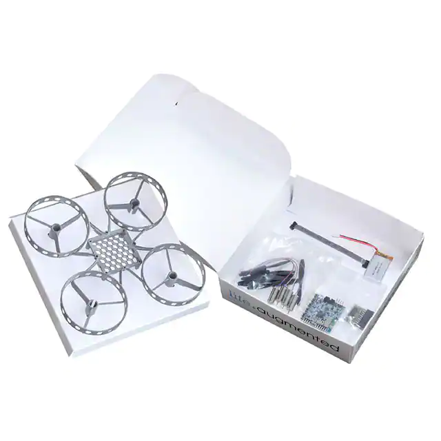
Mini drone kit with flight controller unit, motors, propellers, frame and battery
Features
•
•
•
•
•
•
•
Drone Kit based on the STEVAL-FCU001V1 compact flight controller unit
Four motors: 85x20 mm, 3.7 V
Two clockwise and two counterclockwise 65 mm propellers, plus a couple of
spares
LiPo 3.7 V / 600 mAh battery with a maximum discharge current of 30 C
3D plastic mechanical frame including propeller guards for safety
WEEE and RoHS compliant
Compliant with Directive 2006/66/EC
Description
The STEVAL-DRONE01 mini drone kit features the high performance STEVALFCU001V1 flight controller unit, as well as the motors, propellers, plastic frame and
battery you need to assemble your own mini-drone.
The flight controller unit runs the firmware (STSW-FCU001) to control the speed of
each connected motor and to stabilize the drone. To achieve this, the STM32F4
microcontroller hosted on the board analyses data from the accelerometer and
gyroscope sensors (LSM6DSL and iNEMO 6DoF inertial measurement unit) to
provide highly accurate stability and control.
Product summary
STEVALDRONE01
Mini drone kit with flight
controller unit, motors,
propellers, frame and
battery
STEVALFCU001V1
Flight controller unit
evaluation board for toy
drones
STSWFCU001
Reference design
firmware for mini drones
STM32F4
High-performance MCUs
with DSP and FPU
instructions
SPBTLE-RF
Very low power module
for Bluetooth Smart v4.1
The FCU board includes a Bluetooth Low Energy SPBTLE-RF module, so you can
turn your smartphone running a dedicated App into a remote control unit.
DB3749 - Rev 2 - November 2018
For further information contact your local STMicroelectronics sales office.
www.st.com
�STEVAL-DRONE01
Schematic diagrams
1
Schematic diagrams
Figure 1. STEVAL-FCU001V1 – block diagram
CN1
Micro
USB
STC4054
LD39015
Battery charger
LDO
P8
3V3
SPBTLE-RF
BLE module
LiPo 1-cell
battery
P1, P2,
P4, P5
BT1
USB
LSM6DSL
A + G IMU
LIS2MDL
Magnetometer
LPS22HD
JTAG
connector
SPI2
ESC x 4
JTAG
SPI1
TIM4
PWM out
Power MOS x4
STL6N3LLH6
32-bit MCU
TIM2 input
capture
Pressure Sensor
PWM
4 x 3-ph
motor
4x
DC
motor
P1, P2,
P4, P5
Remocon RX*
P6
UART
connector
UART1
P7
I2C
connector
I2C2
P3
STM32F401
Figure 2. STEVAL-FCU001V1 – circuit schematic (1 of 4)
SPBTLE-RF
U1
ANT.
3
BLE_IRQ
SMD 0805
R1
47k
DB3749 - Rev 2
4
IRQ
VDD
C1
16V 1µF
SMD 0402
5
RESETN
NC1
SPI_CS
SPI_MOSI
NC2
SPI_IRQ
SPI_MISO
VIN
SPI_CLK
11
RST
10
CSN
9
MOSI
8
MISO
7
CLK
BLE_RSTN
BLE_CS
S1_MOSI
S1_MISO
S1_CLK
GND
2
EXT_LPCLK
SPBTLE-RF
6
1
page 2/7
�VDD
1
2
3
4
5
6
SW D
1
3
5
7
9
P8
2
4
6
8
10
S1
C5
100n
R24
10K
R23
10K
VDD
NRST
C8
15pF
GND
3
R5
10K
D2
BAT60 J
17
18
S1_MOS I
BLE_C S
VDD
4.7uF
I2C2_SC L
C11
BLE_RST N
24
23
22
21
20
VBAT_SENS E 19
15
16
S1_CL K
S1_MISO
14
BLE_IRQ
12
TIM2_CH 3
13
11
TIM2_CH 2
TIM2_CH 4
10
VDD 9
8
7
6
TIM2_CH 1
NRST
OSC_16MHZ_OU T
5
4
2
3
1
USB_Mon itor
VDD
LPS22HB_C S
C9
15pF
MOTOR2 -
GND
STM32F401CC U
VDD3
VSS4
VCAP1
PB10
PB2
PB1
PB0
PA7
PA6
PA5
PA4
PA3
PA2
PA1
PA0
VDDA
VSSA
NRST
PH1_OSC_OUT
PH0_OSC_IN
MOTOR 3
R15
MOTOR 3
3
R7
10K
Solder_Bridge
R19
MOTOR 4
PB12
PB13
PB14
PB15
PA8
PA9
PA10
PA11
PA12
PA13
VSS
VDD
PA14
PA15
PB3
PB4
PB5
PB6
PB7
BOOT0
PB8
PB9
VSS1
VDD2
R17 Solder_Bridge
MOTOR4 -
MOTOR 3
VDD
USART1_T X
LSM6DS33_C S
S2_SD A
30
29
28
S2_CL K
LIS2MDL_C S
26
25
27
USB_D M
USART1_R X
31
USB_D P
33
32
SW DD
34
35
SW CLK
37
36
38
39
40
I2C2_SD A
MOTOR 1
42
41
MOTOR 2
43
44
MOTOR 4
46
VDD
45
47
48
0 DNM
Q3
VBAT +
VBAT +
GND
LD1
MOTOR 4R8
1k
RED
Motor_Panel4
1
2
P5
Motor_Panel3
1
2
P2
STL6N3LLH 6
LD2
RED
R21
R20
GND
2.2K
2.2K
R9
3
10K
MOTOR4 -
D4
BAT60 J
MOTOR3 -
D3
BAT60 J
GND
0 DNM
R13
1k
R6
MOTOR3 -
STL6N3LLH 6
Q2
PC15_OSC32_OUT
PC14_OSC32_IN
PC13
VBAT
U2
Solder Bridge have to support 3A peak
Motor_Panel2
1
2
P4
Motor_Panel1
1
2
P1
OSC_16MHZ_ IN
C7
1u
VBAT +
VBAT +
16MHz
Y1
C6
100n
SW DD
SW CLK
C10
100nF
NRST
R22
100k
VDD
RS:505-9192
C&K KMR231GLFS
FC_Signal
TIM2_CH 1
TIM2_CH 2
TIM2_CH 3
TIM2_CH 4
P6
C4
100n
R18
MOTOR 2
Solder_Bridge
0 DNM
R16
0 DNM
R14
MOTOR 1
GND
MOTOR 2 R3
1k
STL6N3LLH 6
Q1
Solder_Bridge
R12
3
4
8
MOTOR1 -
GND
R4
10K
MOTOR2 -
C3
100n
VBAT +
VDD
MOTOR 1 R2
1k
7
2
1
5
6
MOTOR1 7
2
1
5
6
4
8
D1
BAT60 J
Exp_Pad
49
7
2
1
5
6
4
8
7
2
1
5
6
DB3749 - Rev 2
VDD
GND
4
8
VBAT +
GND
USART1_R X
USART1_T X
USB_D P
USB_D M
USB_Mon itor
SW DD
SW CLK
MOTOR1 MOTOR2 MOTOR3 MOTOR4 -
S2_SD A
USART1_T X
USART1_R X
i2Q
1
2
3
4
P3
R11
20K
R10
10K
VBAT +
I2C2_SD A
I2C2_SC L
TIM2_CH 1
TIM2_CH 2
TIM2_CH 3
TIM2_CH 4
S1_CL K
S1_MISO
S1_MOS I
BLE_IRQ
BLE_C S
BLE_RST N
LPS22HB_C S
LIS2MDL_C S
LSM6DS33_C S
S2_CL K
VDD
VDD
STL6N3LLH 6
Q4
VBAT_SENS E
USB_D P
USB_D M
USB_Mon itor
SW DD
SW CLK
MOTOR1 MOTOR2 MOTOR3 MOTOR4 -
S2_SD A
USART1_T X
USART1_R X
TIM2_CH 1
TIM2_CH 2
TIM2_CH 3
TIM2_CH 4
S1_CL K
S1_MISO
S1_MOS I
BLE_IRQ
BLE_C S
BLE_RST N
LPS22HB_C S
LIS2MDL_C S
LSM6DS33_C S
S2_CL K
USART
1
2
3
4
P7
C2
100nF
STEVAL-DRONE01
Schematic diagrams
Figure 3. STEVAL-FCU001V1 – circuit schematic (2 of 4)
page 3/7
�GND
C14
1µF
V_USB
USB_Monitor
GND
R30
5.1K
5
4
R29
1
510R
STC4054
PROG
VCC
U4
USB_DP
3
2
1
CHRG
GND
BAT
D2
GND
D1
U3
D3
VBus
D6
4
5
6
DM
DP
2
1
2
3
GND
BT1
Battery
LD3
RED LED VBAT+
ESDA7P60-1U1M
USBULC6-2M6(uQFN)
uQFN6X145X1
D5
100K
SMD 0402
R28
USB_DM
V_USB
R27
100K
SMD 0402
C15
100nF
USB_DM
USB_DP
USB
1
DB3749 - Rev 2
2
V_USB
C16
4.7µF
R26
1M
SMD 0201
C18
100nF
VBAT+
SMD 0402
C12
16V 100nF
DM
DP
3
2
1
EN
GND
IN
U6
NC
OUT
4
5
C17
1µF
VDD
C13 Micro_USB_AB
4.7nF 50V
SMD 0402
RS 702-5481
Molex 47590-0001
1
2
3
4
5
6
7
8
9
CN1
LD39015M33R
V_USB
GND
0R
R25
STEVAL-DRONE01
Schematic diagrams
Figure 4. STEVAL-FCU001V1 – circuit schematic (3 of 4)
page 4/7
�DB3749 - Rev 2
C19
1uF
1uF
C24
VDD
100nF
C20
VDD
100nF
C25
5
4
3
2
100nF
C23
10
9
5
6
2
S2_CLK 1
S2_SDA
S2_CLK
1
LIS2MDL
VDD_IO
VDD
C1
GND
NC
RES
CS
INT
GND1
GND
VDD
NC1
DRDY
GND1
CS
SDA/SDI/SDO
SCL/SPC
U9
LPS22HBTR
SDO/SA0
SDA/SDI/SDO
RES
SCL/SPC
VDD_IO
U7
11
7
8
3
4
12
6
7
8
9
10
LIS2MDL_CS
S2_SDA
LPS22HB_CS
100nF
1uF
LSM6DS33_CS
S2_SDA
S2_CLK
LIS2MDL_CS
S2_SDA
LPS22HB_CS
LSM6DS33_CS
S2_CLK
C22
C21
VDD
LSM6DSL
INT1
INT2
CS
SDO
SDA
SCL
VDD_IO
U8
LIS2MDL_CS
S2_SDA
LPS22HB_CS
LSM6DS33_CS
S2_CLK
4
9
12
1
14
13
5
*2
RES2
GND1
GND
NC
*1
VDD
8
3
11
6
7
10
2
STEVAL-DRONE01
Schematic diagrams
Figure 5. STEVAL-FCU001V1 – circuit schematic (4 of 4)
page 5/7
�STEVAL-DRONE01
Revision history
Table 1. Document revision history
DB3749 - Rev 2
Date
Version
Changes
09-Oct-2018
1
Initial release.
16-Nov-2018
2
Updated cover image
page 6/7
�STEVAL-DRONE01
IMPORTANT NOTICE – PLEASE READ CAREFULLY
STMicroelectronics NV and its subsidiaries (“ST”) reserve the right to make changes, corrections, enhancements, modifications, and improvements to ST
products and/or to this document at any time without notice. Purchasers should obtain the latest relevant information on ST products before placing orders. ST
products are sold pursuant to ST’s terms and conditions of sale in place at the time of order acknowledgement.
Purchasers are solely responsible for the choice, selection, and use of ST products and ST assumes no liability for application assistance or the design of
Purchasers’ products.
No license, express or implied, to any intellectual property right is granted by ST herein.
Resale of ST products with provisions different from the information set forth herein shall void any warranty granted by ST for such product.
ST and the ST logo are trademarks of ST. All other product or service names are the property of their respective owners.
Information in this document supersedes and replaces information previously supplied in any prior versions of this document.
© 2018 STMicroelectronics – All rights reserved
DB3749 - Rev 2
page 7/7
�
很抱歉,暂时无法提供与“STEVAL-DRONE01”相匹配的价格&库存,您可以联系我们找货
免费人工找货