UM0723
User manual
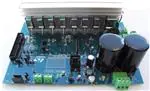
1 kW three-phase motor control demonstration board
featuring L6390 drivers and STGP10NC60KD IGBT
1
Introduction
This document describes the 1 kW three-phase motor control demonstration board featuring
the L6390 high and low-side drivers and the STGP10NC60KD IGBT. The demonstration
board is an AC/DC inverter that generates a three-phase waveform for driving three or twophase motors such as induction motors or PMSM motors up to 1000 W with or without
sensors.
The main device presented in this user manual is a universal, fully evaluated, and populated
design consisting of a three-phase inverter bridge based on the 600 V STMicroelectronics™
IGBT STGP10NC60KD in a TO-220 package mounted on a heatsink, and the L6390 highvoltage high-side and low-side driver featuring an integrated comparator for hardware
protection features such as overcurrent and overtemperature. The driver also integrates an
operational amplifier suitable for advanced current sensing. Thanks to this advanced
characteristic, the system has been specifically designed to achieve an accurate and fast
conditioning of the current feedback, therefore matching the typical requirements in field
oriented control (FOC).
The board has been designed to be compatible with single-phase mains, supplying from
90 VAC to 285 VAC or from 125 VDC to 400 VDC for DC voltage. With reconfiguration of the
input sourcing, the board is suitable also for low-voltage DC applications up to 35 VDC. This
document is associated with the release of the STEVAL-IHM023V2 demonstration board
(see Figure 1 below).
Figure 1.
June 2011
STEVAL-IHM023V2
Doc ID 15870 Rev 4
1/48
�Contents
UM0723
Contents
1
Introduction . . . . . . . . . . . . . . . . . . . . . . . . . . . . . . . . . . . . . . . . . . . . . . . . 1
2
System introduction . . . . . . . . . . . . . . . . . . . . . . . . . . . . . . . . . . . . . . . . . 6
3
4
5
2/48
2.1
Main characteristics . . . . . . . . . . . . . . . . . . . . . . . . . . . . . . . . . . . . . . . . . . 6
2.2
Target applications . . . . . . . . . . . . . . . . . . . . . . . . . . . . . . . . . . . . . . . . . . . 6
2.3
Safety and operating instructions . . . . . . . . . . . . . . . . . . . . . . . . . . . . . . . . 7
2.3.1
General terms . . . . . . . . . . . . . . . . . . . . . . . . . . . . . . . . . . . . . . . . . . . . . 7
2.3.2
Demonstration board intended use . . . . . . . . . . . . . . . . . . . . . . . . . . . . . 7
2.3.3
Demonstration board installation . . . . . . . . . . . . . . . . . . . . . . . . . . . . . . . 7
2.3.4
Electrical connections . . . . . . . . . . . . . . . . . . . . . . . . . . . . . . . . . . . . . . . 8
2.3.5
Demonstration board operation . . . . . . . . . . . . . . . . . . . . . . . . . . . . . . . . 8
Board description . . . . . . . . . . . . . . . . . . . . . . . . . . . . . . . . . . . . . . . . . . . 9
3.1
System architecture . . . . . . . . . . . . . . . . . . . . . . . . . . . . . . . . . . . . . . . . . . 9
3.2
The board schematic . . . . . . . . . . . . . . . . . . . . . . . . . . . . . . . . . . . . . . . . 10
3.3
Circuit description . . . . . . . . . . . . . . . . . . . . . . . . . . . . . . . . . . . . . . . . . . . 16
3.3.1
Power supply . . . . . . . . . . . . . . . . . . . . . . . . . . . . . . . . . . . . . . . . . . . . . 16
3.3.2
Inrush limitation . . . . . . . . . . . . . . . . . . . . . . . . . . . . . . . . . . . . . . . . . . . 17
3.3.3
Brake function . . . . . . . . . . . . . . . . . . . . . . . . . . . . . . . . . . . . . . . . . . . . 17
3.3.4
Gate driving circuit . . . . . . . . . . . . . . . . . . . . . . . . . . . . . . . . . . . . . . . . . 18
3.3.5
Overcurrent protection . . . . . . . . . . . . . . . . . . . . . . . . . . . . . . . . . . . . . . 18
3.3.6
Current sensing amplifying network . . . . . . . . . . . . . . . . . . . . . . . . . . . . 19
3.3.7
The tachometer and Hall/encoder inputs . . . . . . . . . . . . . . . . . . . . . . . . 23
3.3.8
Temperature feedback and overtemperature protection . . . . . . . . . . . . 23
Hardware setting of the STEVAL-IHM023V2 . . . . . . . . . . . . . . . . . . . . . 24
4.1
Hardware settings for six-step (block commutation) control of BLDC
motors . . . . . . . . . . . . . . . . . . . . . . . . . . . . . . . . . . . . . . . . . . . . . . . . . . . 24
4.2
Hardware settings for “Field Oriented Control” (FOC) in single-shunt
topology current reading configuration . . . . . . . . . . . . . . . . . . . . . . . . . . . 26
4.3
Hardware settings for FOC in three-shunt configuration . . . . . . . . . . . . . 27
Description of jumpers, test pins, and connectors . . . . . . . . . . . . . . . 30
Doc ID 15870 Rev 4
�UM0723
Contents
6
Connector placement . . . . . . . . . . . . . . . . . . . . . . . . . . . . . . . . . . . . . . . 33
7
Bill of material . . . . . . . . . . . . . . . . . . . . . . . . . . . . . . . . . . . . . . . . . . . . . 34
8
PCB layout . . . . . . . . . . . . . . . . . . . . . . . . . . . . . . . . . . . . . . . . . . . . . . . . 40
9
Ordering information . . . . . . . . . . . . . . . . . . . . . . . . . . . . . . . . . . . . . . . 44
10
Using STEVAL-IHM023V2 with STM32 PMSM FOC firmware
library v3.0 . . . . . . . . . . . . . . . . . . . . . . . . . . . . . . . . . . . . . . . . . . . . . . . . 44
10.1
Environmental considerations . . . . . . . . . . . . . . . . . . . . . . . . . . . . . . . . . 44
10.2
Hardware requirements . . . . . . . . . . . . . . . . . . . . . . . . . . . . . . . . . . . . . . 45
10.3
Software requirements . . . . . . . . . . . . . . . . . . . . . . . . . . . . . . . . . . . . . . . 45
10.4
STM32 FOC firmware library v3.0 customization . . . . . . . . . . . . . . . . . . . 45
11
Conclusion . . . . . . . . . . . . . . . . . . . . . . . . . . . . . . . . . . . . . . . . . . . . . . . . 47
12
References . . . . . . . . . . . . . . . . . . . . . . . . . . . . . . . . . . . . . . . . . . . . . . . . 47
13
Revision history . . . . . . . . . . . . . . . . . . . . . . . . . . . . . . . . . . . . . . . . . . . 47
Doc ID 15870 Rev 4
3/48
�List of tables
UM0723
List of tables
Table 1.
Table 2.
Table 3.
Table 4.
Table 5.
Table 6.
Table 7.
Table 8.
Table 9.
Table 10.
Table 11.
Table 12.
Table 13.
4/48
Current reading configuration . . . . . . . . . . . . . . . . . . . . . . . . . . . . . . . . . . . . . . . . . . . . . . . 23
Jumper settings for high-voltage BLDC motor in six-step control . . . . . . . . . . . . . . . . . . . . 24
Jumper settings for low-voltage BLDC motor in six-step control . . . . . . . . . . . . . . . . . . . . 25
Jumper settings for high-voltage PMAC or generic AC motor in single-shunt
FOC control . . . . . . . . . . . . . . . . . . . . . . . . . . . . . . . . . . . . . . . . . . . . . . . . . . . . . . . . . . . . 26
Jumper settings for low-voltage BLDC motor in single-shunt FOC control. . . . . . . . . . . . . 27
Jumper settings for FOC of HV PMSM, BLDC, or AC IM in three-shunt configuration
for current reading . . . . . . . . . . . . . . . . . . . . . . . . . . . . . . . . . . . . . . . . . . . . . . . . . . . . . . . 28
Jumper settings for FOC of LV PMSM or BLDC in three-shunt configuration for
current reading . . . . . . . . . . . . . . . . . . . . . . . . . . . . . . . . . . . . . . . . . . . . . . . . . . . . . . . . . . 29
Jumpers description . . . . . . . . . . . . . . . . . . . . . . . . . . . . . . . . . . . . . . . . . . . . . . . . . . . . . . 30
Connector pinout description . . . . . . . . . . . . . . . . . . . . . . . . . . . . . . . . . . . . . . . . . . . . . . . 31
Testing pins description . . . . . . . . . . . . . . . . . . . . . . . . . . . . . . . . . . . . . . . . . . . . . . . . . . . 32
Bill of material . . . . . . . . . . . . . . . . . . . . . . . . . . . . . . . . . . . . . . . . . . . . . . . . . . . . . . . . . . . 34
STEVAL-IHM023V2 motor control workbench parameters . . . . . . . . . . . . . . . . . . . . . . . . 45
Document revision history . . . . . . . . . . . . . . . . . . . . . . . . . . . . . . . . . . . . . . . . . . . . . . . . . 47
Doc ID 15870 Rev 4
�UM0723
List of figures
List of figures
Figure 1.
Figure 2.
Figure 3.
Figure 4.
Figure 5.
Figure 6.
Figure 7.
Figure 8.
Figure 9.
Figure 10.
Figure 11.
Figure 12.
Figure 13.
Figure 14.
Figure 15.
Figure 16.
Figure 17.
Figure 18.
Figure 19.
STEVAL-IHM023V2 . . . . . . . . . . . . . . . . . . . . . . . . . . . . . . . . . . . . . . . . . . . . . . . . . .
Motor control system architecture. . . . . . . . . . . . . . . . . . . . . . . . . . . . . . . . . . . . . . . .
STEVAL- IHM023V2 schematic - part 1 . . . . . . . . . . . . . . . . . . . . . . . . . . . . . . . . . . .
STEVAL- IHM023V2 schematic - part 2 . . . . . . . . . . . . . . . . . . . . . . . . . . . . . . . . . . .
STEVAL- IHM023V2 schematic - part 3 . . . . . . . . . . . . . . . . . . . . . . . . . . . . . . . . . . .
STEVAL- IHM023V2 schematic - part 4 . . . . . . . . . . . . . . . . . . . . . . . . . . . . . . . . . . .
STEVAL- IHM023V2 schematic - part 5 . . . . . . . . . . . . . . . . . . . . . . . . . . . . . . . . . . .
STEVAL- IHM023V2 schematic - part 6 . . . . . . . . . . . . . . . . . . . . . . . . . . . . . . . . . . .
Power supply block diagram . . . . . . . . . . . . . . . . . . . . . . . . . . . . . . . . . . . . . . . . . . . .
Gate driving network . . . . . . . . . . . . . . . . . . . . . . . . . . . . . . . . . . . . . . . . . . . . . . . . . .
Overcurrent protection . . . . . . . . . . . . . . . . . . . . . . . . . . . . . . . . . . . . . . . . . . . . . . . .
Three-shunt configuration . . . . . . . . . . . . . . . . . . . . . . . . . . . . . . . . . . . . . . . . . . . . . .
Six-step current sensing configuration . . . . . . . . . . . . . . . . . . . . . . . . . . . . . . . . . . . .
NTC placement on the heatsink . . . . . . . . . . . . . . . . . . . . . . . . . . . . . . . . . . . . . . . . .
STEVAL-IHM023V2 connectors placement . . . . . . . . . . . . . . . . . . . . . . . . . . . . . . . .
Silk screen - top side . . . . . . . . . . . . . . . . . . . . . . . . . . . . . . . . . . . . . . . . . . . . . . . . .
Silk screen - bottom side . . . . . . . . . . . . . . . . . . . . . . . . . . . . . . . . . . . . . . . . . . . . . .
Copper tracks - top side . . . . . . . . . . . . . . . . . . . . . . . . . . . . . . . . . . . . . . . . . . . . . . .
Copper tracks - bottom side . . . . . . . . . . . . . . . . . . . . . . . . . . . . . . . . . . . . . . . . . . . .
Doc ID 15870 Rev 4
.....1
.....9
. . . . 10
. . . . 11
. . . . 12
. . . . 13
. . . . 14
. . . . 15
. . . . 17
. . . . 18
. . . . 19
. . . . 21
. . . . 22
. . . . 23
. . . . 33
. . . . 41
. . . . 42
. . . . 43
. . . . 43
5/48
�System introduction
UM0723
2
System introduction
2.1
Main characteristics
The information below lists the converter specification data and the main parameters set for
the STEVAL-IHM023V2 demonstration board.
2.2
6/48
●
Minimum input voltage 125 VDC or 90 VAC
●
Maximum input voltage 400 VDC or 285 VAC
●
With applied input voltage doubler - the range is from 65 VAC to 145 VAC
●
Voltage range for low-voltage motor control applications from 18 VDC to 35 VDC
●
Possibility to use auxiliary +15 V supply voltage
●
Maximum output power for motors up to 1000 W
●
Regenerative brake control feature
●
Input inrush limitation with bypassing relay
●
+ 15 V auxiliary power supply based on buck converter with VIPer™16
●
IGBT power switch STGP10NC60KD in TO-220 package - compatible with other ST
IGBTs or power MOSFETs in TO-220 package
●
Fully populated board conception with testing points and isolated plastic safety cover
●
Motor control connector for interface with STM3210B-EVAL board and other ST motor
control dedicated kits
●
Tachometer input
●
Hall/encoder inputs
●
Possibility to connect BEMF daughterboard for sensorless six-step control of BLDC
motors
●
PCB type and size:
–
Material of PCB - FR-4
–
Double-sided layout
–
Copper thickness: 60 µm
–
Total dimensions of demonstration board: 127 mm x 180 mm.
Target applications
●
Washing machines
●
Home appliances
●
Medical applications - rehabilitative beds
●
High-power, high-efficiency water pumps for heating applications.
Doc ID 15870 Rev 4
�UM0723
System introduction
2.3
Safety and operating instructions
2.3.1
General terms
Warning:
During assembly, testing, and operation, the demonstration
board poses several inherent hazards, including bare wires,
moving or rotating parts, and hot surfaces. There is a danger
of serious personal injury and damage to property, if the kit
or components are improperly used or installed incorrectly.
The kit is not electrically isolated from the AC/DC input. The
demonstration board is directly linked to the mains voltage.
No insulation has been placed between the accessible parts
and the high-voltage. All measurement equipment must be
isolated from the mains before powering the board. When
using an oscilloscope with the demonstration board, it must
be isolated from the AC line. This prevents a shock from
occurring as a result of touching any single point in the
circuit, but does NOT prevent shocks when touching two or
more points in the circuit. Do not touch the demonstration
board after disconnection from the voltage supply, as several
parts and power terminals, which contain energized
capacitors, need to be allowed to discharge.
All operations involving transportation, installation and use, as well as maintenance, are to
be carried out by skilled technical personnel (national accident prevention rules must be
observed). For the purpose of these basic safety instructions, “skilled technical personnel”
are suitably qualified people who are familiar with the installation, use and maintenance of
powered electronic systems.
2.3.2
Demonstration board intended use
The STEVAL-IHM023V2 demonstration board is a component designed for demonstration
purposes only and is not to be used for electrical installation or machinery. The technical
data as well as information concerning the power supply conditions should be taken from
the documentation and strictly observed.
2.3.3
Demonstration board installation
The installation and cooling of the demonstration kit boards must be in accordance with the
specifications and the targeted application.
●
The motor drive converters are protected against excessive strain. In particular, no
components are to be bent or isolating distances altered during the course of
transportation or handling.
●
No contact must be made with other electronic components and contacts.
●
The boards contain electro-statically sensitive components that are prone to damage
through improper use. Electrical components must not be mechanically damaged or
destroyed.
Doc ID 15870 Rev 4
7/48
�System introduction
2.3.4
UM0723
Electrical connections
Applicable national accident prevention rules must be followed when working on the main
power supply with a motor drive. The electrical installation must be completed in accordance
with the appropriate requirements.
2.3.5
Demonstration board operation
A system architecture which supplies power to the demonstration board should be equipped
with additional control and protective devices in accordance with the applicable safety
requirements (e.g. compliance with technical equipment and accident prevention rules).
8/48
Doc ID 15870 Rev 4
�UM0723
Board description
3
Board description
3.1
System architecture
A generic motor control system can be basically schematized as the arrangement of four
main blocks (see Figure 2 below).
●
A control block - its main task is to accept user commands and motor drive
configuration parameters and to provide all digital signals to implement the proper
motor driving strategy. The ST demonstration board based on the STM32™
microcontroller STM3210B-EVAL can be used as a control block thanks to the motor
control connector used on the board.
●
A power block - makes a power conversion from the DC bus transferring to the motor
by means of a three-phase inverter topology. The power block is based on high-voltage
(high and low-side) drivers (L6390) and power switches (STGP10NC60KD) in TO-220
packages.
●
The motor itself - the STEVAL-IHM023V2 demonstration board is able to properly
drive any PMSM, but the FOC itself is conceived for sinusoidal-shaped BEMF. The
demonstration board is also suitable for driving any three or two-phase asynchronous
motor or low-voltage BLDC motors.
●
Power supply block - able to work from 90 VAC to 285 VAC or from 125 VDC to
400 VDC. With reconfiguration of the power stage with jumpers, the board can also be
used for low-voltage applications from 18 VDC to 35 VDC. By supplying the electronic
parts on the board through an external + 15 V connector, the board can be used for
a wide voltage range up to 400 VDC. Please refer to Section 4 for detailed settings of
the jumpers according to the required application.
Figure 2.
Motor control system architecture
#ONTROLBLOCK
-/4/2
0OWERSUPPLY
0OWERBLOCK
!-�����6�
Referring to the above motor control system architecture, the STEVAL-IHM023V2 includes
the power supply and the power block hardware blocks.
Doc ID 15870 Rev 4
9/48
�*�
�
�
�
�
�
Doc ID 15870 Rev 4
2���
���2
$��
":8��"��6
2���
VO LTAGEOFF
"#���
1��
2��
2���
#��
���N&
! "
7��
�
2���
�"US
�
�
#��
���N&
2���
#��
"#��� ���N&
1��
2��
�
�
�
VO LTAGEOFF
2��
#��
7�
#��
���
P&
2��
���6
"RAKECONTROL
1�
"#���
2��
-?PHASE?#
-?PHASE?"
-?PHASE?!
#��
���N&
#��
��P&
(��! �
#��
��P&
"#���
1��
#��
��P&
2��
#��
���N&
5�
� 43���),4
�
3OFTWAREBRAKE
2��
2��
���6
$�� " :8��"��6
2���
2��
�
��
��
1��
"#���
5��&
-��(#��-�2
��
5��%
-��(#��-�2
�
5��$
-��(#��-�2
�
1��
"#���
1��
"#���
2���
5��#
-��(#��-�2 2���
�
��
��
�
�
�
5��"
-��(#��-�2
2��� 2��� 2���
2��
#��
�N&
2��
2��
2��
1�
"#���"
1��
"#���
$��
#��
���N&
2���
2��
$��
344(�,��
#��
���
N&
2"RAKE
*�
�
�
#��
���N&
-?PHASE?!
!-�����
1�
34'0��.#��+$
1�
"#���
2��
4ACH O
2��
.�#�
7�
�"US
$��
2��
$��
,%$2ED
2���
��
���6
#��
���N&
"RAKECONTROL
2��
���6
4ACH O
�
�
*�
6DD?MICRO
4ACHOSENSOR
"!4��*&),-
���6
��6
6DD?MICRO
%NCODER�HALL
(��!�
(��"�
(��:�
������6
'.$
2���
�
"!4��*&),-
�
�
6DD?MICRO
Figure 3.
10/48
5��!
-��(#��-�2 2���
3.2
�
(ALL�ENCODER
Board description
UM0723
The board schematic
STEVAL- IHM023V2 schematic - part 1
�6)0ER
).054
�
�
�
�
*�
Doc ID 15870 Rev 4
�
$RAIN�
$RAIN�
$RAIN�
$RAIN�
����6
62�
3OURCE�
3OURCE�
3OURCE�
3OURCE�
�
�
�
�
�
$�
344(�,��!
2���
.�#�
#/-0
6$$
,)&"
�
�
�
���6
#��
�
+"5�+
RELAY?"
5� 6)0ER��,$
"UCKCONVERTER
��
��
��
��
#��
,�
#�
���N&�8 �
&� &53%
�
����!4%-0
RELAY?!
7��
#�
���N&�9�
#�
���N&�9�
,�
(
#�� #��
��N& .�#�
2�
2��
2�
2�
2�
2�
���N& ���6
2��
.�#�
$�
344(�,��!
#�� #��
�
#��
���N&
6OL TAGE?DOUBLER
$�
$#?BUS?VOLTAGE
$�
":6��#��3-$
�
�
�
����6
����6
���6
��6
#�
#�
#�
��N&
#�
���N&
�
).
'.$
�
/54
�
5� ,$����3��423/4���
2�
$�
"!4��*&),-
����6LINEAR
2�
2�
2�
7�
�
#�
���N& � #�
�
"US?VOLTAGE
6DD?MICRO
�"US
!-�����
���� 6
����6
6DD?MICRO
�� 6
Figure 4.
�
)NPUTPARTWITHBRIDGE
UM0723
Board description
STEVAL- IHM023V2 schematic - part 2
11/48
�12/48
Doc ID 15870 Rev 4
3OFTWAREBRAKE
/#0OFF
.4#BYPASSRELAY
7�
"
!
-/4/ 2
�
�
1�
"#���
�
07-?6REF
-?PHASE?!
-?PHASE?"
�
�
��
��
��
���6$#
�
�
*�
�
�
�
�
��
��
��
��
��
��
��
��
��
��
��
��
��
���6
2��
�
7�
-?PHASE?#
6DD?MCU
(ET?TEMPERATURE
��6LINEAR
#��
���N&
6DD?MICR O
��6MAX�
#��
���N&
).
$�
�.����
�
*�
�
�
�
�
�
�
�
�
$�
#�� 3403����
���N&
07-?6REF
�"US
���� 6
6DD? MICR O
PHASE? #
PHASE? "
PHASE? !
"%-&DAUGHTERBOARD
'.$
�
/54
5�
,-����?�
#��
���N&
�
�� 6
� #��
#!0!#)4/20/,?�
,6$#BUSSUPPLY
�
����LINEBAR
/54
'.$
�
$�
3-�4��!
).
5�� ,��-��!#$4
42$0!+
�
���6/.,9 ,6
SU PPLY
7�
���6
()'(6/,4!'%
"US?VO LTAGE
6)0ER
�"US
$�
,%$GREEN
-OTORCONNECTOR
-OTORCONNECTOR
�
�
�
�
�
��
��
��
��
��
��
��
��
��
��
��
��
RELAY? "
RELAY? !
���6
#��
���N&
���6EX�SUPPLY
&).$%2����
��
,3�
$��
,%$YELLOW
2��
%-?34/0
07-
!
(
07-
!
,
07-
"
(
07-
"
,
07-
#
(
07-
#
,
#URRE NT?!
#URRE NT?"
#URRE NT?#
.4#?BYPASS?RELAY
2��
2���
$��
�.����
2��
.4#BYPASS
PHASE?#
PHASE?"
PHASE?!
*�
!-�����
���6
Figure 5.
�
�
�
*�
-OTOROUTPUT
Board description
UM0723
STEVAL- IHM023V2 schematic - part 3
�2��
Doc ID 15870 Rev 4
#��
��N&
T
24�
2��
����6
(ET?TEMPERATURE
#��
#��
��P& ��P&
2�� �
(EATSINKTEMPERATURE
07 -
!
(
2���
�3$
#��
40��
40��
/#0OF F
#URRENT ?"
#URRENT ?!
07-
#
(
07-
#
,
07-
"
(
07-
"
,
07-
!
(
07-
!
,
PHASE?#
40��
40��
40��
40��
40��
40��
40��
40��
40��
40��
4ESTPINS
PHASE?"
�� 6
6DD?MICRO
5�
��
��
��
��
��
��
��
�
2��
6BOOT
(6'
/54
.#
.#
,6'
#0�
/0�
#�� ���P&
$�� "!4��*&),-
2��
�,).
�3$�/$
().
6CC
$4
/0
/0/54
'.$
,����$
�
�
�
�
�
�
�
�
PHASE?!
#��
���N&
#URRENT?!
�N&
40��
40�
40�
40�
40�
40�
40�
40�
40�
40�
2��
���6
#��
���P&
2��
2��
2��
2��
2��.�#�
REF
���6
����6
"RAKECONTROL
"US?VOLTAGE
-?PHASE?#
-?PHASE?"
-?PHASE?!
#URRENT ?#
#��
��P&
2��
#�� #��
REF�
2��
���� 6
2��
2���
2���
�
�
�
�
�
�"US
�3(
���P&
#��
2��
� �
�
�
�
#��
���N&
(ET.4#COMPARATOR
2��
.�#�
7�
1�
34'0��.#��K$
�3(
PHASE?!
1�
34'0��.#��K$
5�
43����"),4
2��
�
�
�
(ET?TEMPERATURE
�
#��
���N&
2�
2�
$���.����
$��� .����
43���),4
�
5�
#?%
!-�����
�3$
���� 6
Figure 6.
07 -
!
,
2��
���� 6
(6(�,SIDEDRIVERCHANNEL!
UM0723
Board description
STEVAL- IHM023V2 schematic - part 4
$�� "!4��*&),-
13/48
�14/48
Doc ID 15870 Rev 4
%-?34/0
6DD?MICRO
2��
#��
��P&
#��
���P&
2��
#��
��P&
2�� �
2�
#��
���N&
/#0/&&
#URRE NT?"
6DD?MICRO
2�
�N&
#��
���6
2��
�3$
�3$
�
�
�
�
�
�
�
�
5�
��
��
��
��
��
��
��
�
#�� ���P&
$�� "!4��*&),-
7��'AIN?�
2��
�, ).
6BOOT
�3 $�/$ (6'
().
/54
6CC
.#
$4
.#
/0
,6'
/0/54 #0�
'.$
/0�
,����$
#��
���P&
2��
#��
��P&
2�� .�#�
2��
2��
2��
#�� #�� 2��
����6
2��
#��
�N&
2�
$��� .����
$��� .����
�
�
�
�
�
�
�
2�
7��
!
"
2��
.�#�
�
�
2��
2��
2�
2����
2��
1�
34'0��.#��+$
PHASE?"
1�
34'0��.#��+$
�"US
!-�����6�
���� 6
#?%
Figure 7.
07-
"
(
07-
"
,
2��
���� 6
(6(�,SIDEDRIVERCHANNEL "
Board description
UM0723
STEVAL- IHM023V2 schematic - part 5
$�� "!4��*&),-
�07-
#
(
07-
#
,
2��
2��
2���
2���
#��
��P&
���� 6
#��
��P&
�3$
2��
Doc ID 15870 Rev 4
#��
���N&
/#0/&&
#URRENT?#
6DD? MICRO
2���
#��
�N&
���6
6BOOT
(6'
/54
.#
.#
,6'
#0�
/0�
5�
$�� "!4��*&),-
#�� ���P&
�,).
�3$�/$
() .
6CC
$4
/0
/0/54
'. $
2��
�
�
�
�
�
�
�
�
,����$
#��
���P&
2��
��
��
��
��
��
��
��
�
#��
2��
2��
2��
2��
#��
��P&
2��.�#�
#��
2���
���� 6
2��
�K
$��� .����
2�
#��
���N&
2���
$��� .����
2���
�
�
�
�
�
�
2���
.�#�
7��
�3(
�3(
1��
34'0��.#��+$
PHASE?#
1��
34'0��.#��+$
�"US
!-�����6�
#?%
Figure 8.
(6(�,SIDEDRIVERCHANNEL #
UM0723
Board description
STEVAL- IHM023V2 schematic - part 6
$�� "!4��*&),-
15/48
�Board description
3.3
Circuit description
3.3.1
Power supply
UM0723
The power supply in the STEVAL-IHM023V2 demonstration board is implemented as
a multifunctional block which allows to supply the inverter in all ranges of input voltage up to
285 VAC or 400 VDC. If the input AC voltage does not surpass 145 VAC, it is possible to
apply the input voltage doubler, this is done by shorting the W14 jumper. This configuration
almost doubles the input AC voltage to a standard level and allows to evaluate the motor
control application with a low level of input AC voltage.
For high-voltage applications it is necessary to set W3 jumpers to position “HIGH
VOLTAGE”, the auxiliary power supply for supplying all active components on the
demonstration board is implemented as a buck converter based on the U6 VIPer16L which
works with fixed frequency 60 kHz. The output voltage of the converter is +15 VDC voltage
which is fed into the L6390 drivers as supply voltage as well as into the linear regulator
L78L33ACD and L78M05ACDT. The linear regulator provides +3.3 VDC and +5 VDC for
supplying the operational amplifiers and other related parts placed on the demonstration
board. The selection of supply voltage for hardware peripherals placed on the board is done
with jumper W1. In the “3.3 V” position the supply voltage selected is +3.3 V and in the “5 V”
position it is +5 V. Thanks to jumper W6, it is possible to supply the connected MCU driving
board with related supply voltage. In this case, the maximal consumptive current of the MCU
unit has not overreached 50 mA. Please refer to the ST released VIPer16LD datasheet for
further information on this concept.
For low-voltage applications, the step-down converter must be disabled by setting the W3
jumper to position “