STM32F103x6 STM32F103x8 STM32F103xB
Performance line, ARM-based 32-bit MCU with Flash, USB, CAN, seven 16-bit timers, two ADCs and nine communication interfaces
Preliminary Data
Features
■
Core: ARM 32-bit Cortex™-M3 CPU – 72 MHz, 90 DMIPS with 1.25 DMIPS/MHz – Single-cycle multiplication and hardware division – Nested interrupt controller with 43 maskable interrupt channels – Interrupt processing (down to 6 CPU cycles) with tail chaining
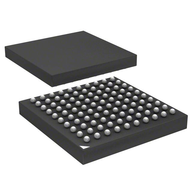
LQFP48 7 x 7 mm LQFP100 14 x 14 mm LQFP64 10 x 10 mm BGA100 10 x 10 mm
■
Debug mode – Serial wire debug (SWD) & JTAG interfaces Up to 80 fast I/O ports – 32/49/80 5 V-tolerant I/Os – All mappable on 16 external interrupt vectors – Atomic read/modify/write operations
■
■
Memories – 32-to-128 Kbytes of Flash memory – 6-to-20 Kbytes of SRAM
■
Clock, reset and supply management – 2.0 to 3.6 V application supply and I/Os – POR, PDR, and programmable voltage detector (PVD) – 4-to-16 MHz quartz oscillator – Internal 8 MHz factory-trimmed RC – Internal 32 kHz RC – PLL for CPU clock – Dedicated 32 kHz oscillator for RTC with calibration
■
Up to 7 timers – Up to three 16-bit timers, each with up to 4 IC/OC/PWM or pulse counter – 16-bit, 6-channel advanced control timer: up to 6 channels for PWM output Dead time generation and emergency stop – 2 x 16-bit watchdog timers (Independent and Window) – SysTick timer: a 24-bit downcounter
■
Low power – Sleep, Stop and Standby modes – VBAT supply for RTC and backup registers
■
Up to 9 communication interfaces – Up to 2 x I2C interfaces (SMBus/PMBus) – Up to 3 USARTs (ISO 7816 interface, LIN, IrDA capability, modem control) – Up to 2 SPIs (18 Mbit/s) – CAN interface (2.0B Active) – USB 2.0 full speed interface
■
2 x 12-bit, 1 µs A/D converters (16-channel) – – – – Conversion range: 0 to 3.6 V Dual-sample and hold capability Synchronizable with advanced control timer Temperature sensor
■
DMA – 7-channel DMA controller – Peripherals supported: timers, ADC, SPIs, I2Cs and USARTs
Table 1.
Reference
Device summary
Root part number STM32F103C8, STM32F103R8 STM32F103V8
STM32F103x6 STM32F103C6, STM32F103R6 STM32F103x8
STM32F103xB STM32F103RB STM32F103VB
July 2007
Rev 2
1/67
www.st.com 1
This is preliminary information on a new product now in development or undergoing evaluation. Details are subject to change without notice.
�Contents
STM32F103xx
Contents
1 2 Introduction . . . . . . . . . . . . . . . . . . . . . . . . . . . . . . . . . . . . . . . . . . . . . . . . 6 Description . . . . . . . . . . . . . . . . . . . . . . . . . . . . . . . . . . . . . . . . . . . . . . . . . 6
2.1 2.2 Device overview . . . . . . . . . . . . . . . . . . . . . . . . . . . . . . . . . . . . . . . . . . . . . 7 Overview . . . . . . . . . . . . . . . . . . . . . . . . . . . . . . . . . . . . . . . . . . . . . . . . . . 8
3 4 5
Pin descriptions . . . . . . . . . . . . . . . . . . . . . . . . . . . . . . . . . . . . . . . . . . . 15 Memory mapping . . . . . . . . . . . . . . . . . . . . . . . . . . . . . . . . . . . . . . . . . . 22 Electrical characteristics . . . . . . . . . . . . . . . . . . . . . . . . . . . . . . . . . . . . 23
5.1 Test conditions . . . . . . . . . . . . . . . . . . . . . . . . . . . . . . . . . . . . . . . . . . . . . 23
5.1.1 5.1.2 5.1.3 5.1.4 5.1.5 5.1.6 5.1.7 Minimum and maximum values . . . . . . . . . . . . . . . . . . . . . . . . . . . . . . . 23 Typical values . . . . . . . . . . . . . . . . . . . . . . . . . . . . . . . . . . . . . . . . . . . . . 23 Typical curves . . . . . . . . . . . . . . . . . . . . . . . . . . . . . . . . . . . . . . . . . . . . 23 Loading capacitor . . . . . . . . . . . . . . . . . . . . . . . . . . . . . . . . . . . . . . . . . 23 Pin input voltage . . . . . . . . . . . . . . . . . . . . . . . . . . . . . . . . . . . . . . . . . . 23 Power supply scheme . . . . . . . . . . . . . . . . . . . . . . . . . . . . . . . . . . . . . . 24 Current consumption measurement . . . . . . . . . . . . . . . . . . . . . . . . . . . 25
5.2 5.3
Absolute maximum ratings . . . . . . . . . . . . . . . . . . . . . . . . . . . . . . . . . . . . 26 Operating conditions . . . . . . . . . . . . . . . . . . . . . . . . . . . . . . . . . . . . . . . . 27
5.3.1 5.3.2 5.3.3 5.3.4 5.3.5 5.3.6 5.3.7 5.3.8 5.3.9 5.3.10 5.3.11 5.3.12 5.3.13 General operating conditions . . . . . . . . . . . . . . . . . . . . . . . . . . . . . . . . . 27 Operating conditions at power-up / power-down . . . . . . . . . . . . . . . . . . 27 Embedded reset and power control block characteristics . . . . . . . . . . . 28 Embedded reference voltage . . . . . . . . . . . . . . . . . . . . . . . . . . . . . . . . . 28 Supply current characteristics . . . . . . . . . . . . . . . . . . . . . . . . . . . . . . . . 29 External clock source characteristics . . . . . . . . . . . . . . . . . . . . . . . . . . . 33 Internal clock source characteristics . . . . . . . . . . . . . . . . . . . . . . . . . . . 37 PLL characteristics . . . . . . . . . . . . . . . . . . . . . . . . . . . . . . . . . . . . . . . . 38 Memory characteristics . . . . . . . . . . . . . . . . . . . . . . . . . . . . . . . . . . . . . 39 EMC characteristics . . . . . . . . . . . . . . . . . . . . . . . . . . . . . . . . . . . . . . . . 40 Absolute maximum ratings (electrical sensitivity) . . . . . . . . . . . . . . . . . 42 I/O port pin characteristics . . . . . . . . . . . . . . . . . . . . . . . . . . . . . . . . . . . 43 NRST pin characteristics . . . . . . . . . . . . . . . . . . . . . . . . . . . . . . . . . . . . 47
2/67
�STM32F103xx 5.3.14 5.3.15 5.3.16 5.3.17 5.3.18
Contents TIM timer characteristics . . . . . . . . . . . . . . . . . . . . . . . . . . . . . . . . . . . . 48 Communications interfaces . . . . . . . . . . . . . . . . . . . . . . . . . . . . . . . . . . 49 CAN (controller area network) interface . . . . . . . . . . . . . . . . . . . . . . . . . 54 12-bit ADC characteristics . . . . . . . . . . . . . . . . . . . . . . . . . . . . . . . . . . . 54 Temperature sensor characteristics . . . . . . . . . . . . . . . . . . . . . . . . . . . . 58
6
Package characteristics . . . . . . . . . . . . . . . . . . . . . . . . . . . . . . . . . . . . . 59
6.1 Thermal characteristics . . . . . . . . . . . . . . . . . . . . . . . . . . . . . . . . . . . . . . 64
7
Order codes . . . . . . . . . . . . . . . . . . . . . . . . . . . . . . . . . . . . . . . . . . . . . . . 65
7.1 Future family enhancements . . . . . . . . . . . . . . . . . . . . . . . . . . . . . . . . . . 65
8
Revision history . . . . . . . . . . . . . . . . . . . . . . . . . . . . . . . . . . . . . . . . . . . 66
3/67
�List of tables
STM32F103xx
List of tables
Table 1. Table 2. Table 3. Table 4. Table 5. Table 6. Table 7. Table 8. Table 9. Table 10. Table 11. Table 12. Table 13. Table 14. Table 15. Table 16. Table 17. Table 18. Table 19. Table 20. Table 21. Table 22. Table 23. Table 24. Table 25. Table 26. Table 27. Table 28. Table 29. Table 30. Table 31. Table 32. Table 33. Table 34. Table 35. Table 36. Table 37. Table 38. Table 39. Table 40. Table 41. Table 42. Table 43. Table 44. Table 45. Table 46. Table 47. Device summary . . . . . . . . . . . . . . . . . . . . . . . . . . . . . . . . . . . . . . . . . . . . . . . . . . . . . . . . . . 1 Device features and peripheral counts (STM32F103xx performance line). . . . . . . . . . . . . . 7 Pin definitions . . . . . . . . . . . . . . . . . . . . . . . . . . . . . . . . . . . . . . . . . . . . . . . . . . . . . . . . . . . 18 Voltage characteristics . . . . . . . . . . . . . . . . . . . . . . . . . . . . . . . . . . . . . . . . . . . . . . . . . . . . 26 Current characteristics . . . . . . . . . . . . . . . . . . . . . . . . . . . . . . . . . . . . . . . . . . . . . . . . . . . . 26 Thermal characteristics. . . . . . . . . . . . . . . . . . . . . . . . . . . . . . . . . . . . . . . . . . . . . . . . . . . . 27 General operating conditions . . . . . . . . . . . . . . . . . . . . . . . . . . . . . . . . . . . . . . . . . . . . . . . 27 Operating conditions at power-up / power-down . . . . . . . . . . . . . . . . . . . . . . . . . . . . . . . . 27 Embedded reset and power control block characteristics. . . . . . . . . . . . . . . . . . . . . . . . . . 28 Embedded internal reference voltage . . . . . . . . . . . . . . . . . . . . . . . . . . . . . . . . . . . . . . . . . 28 Maximum current consumption in Run and Sleep modes . . . . . . . . . . . . . . . . . . . . . . . . . 29 Maximum current consumption in Stop and Standby modes . . . . . . . . . . . . . . . . . . . . . . . 30 Typical current consumption in Run and Sleep modes . . . . . . . . . . . . . . . . . . . . . . . . . . . 31 Typical current consumption in Stop and Standby modes . . . . . . . . . . . . . . . . . . . . . . . . . 32 High-speed external (HSE) user clock characteristics . . . . . . . . . . . . . . . . . . . . . . . . . . . . 33 Low-speed external user clock characteristics . . . . . . . . . . . . . . . . . . . . . . . . . . . . . . . . . . 33 HSE 4-16 MHz oscillator characteristics. . . . . . . . . . . . . . . . . . . . . . . . . . . . . . . . . . . . . . . 35 LSE oscillator characteristics (fLSE = 32.768 kHz) . . . . . . . . . . . . . . . . . . . . . . . . . . . . . . . 36 HSI oscillator characteristics. . . . . . . . . . . . . . . . . . . . . . . . . . . . . . . . . . . . . . . . . . . . . . . . 37 LSI oscillator characteristics . . . . . . . . . . . . . . . . . . . . . . . . . . . . . . . . . . . . . . . . . . . . . . . 37 Low-power mode wakeup timings . . . . . . . . . . . . . . . . . . . . . . . . . . . . . . . . . . . . . . . . . . . 38 PLL characteristics . . . . . . . . . . . . . . . . . . . . . . . . . . . . . . . . . . . . . . . . . . . . . . . . . . . . . . . 38 Flash memory characteristics . . . . . . . . . . . . . . . . . . . . . . . . . . . . . . . . . . . . . . . . . . . . . . . 39 Flash memory endurance and data retention . . . . . . . . . . . . . . . . . . . . . . . . . . . . . . . . . . . 39 EMS characteristics . . . . . . . . . . . . . . . . . . . . . . . . . . . . . . . . . . . . . . . . . . . . . . . . . . . . . . 40 EMI characteristics . . . . . . . . . . . . . . . . . . . . . . . . . . . . . . . . . . . . . . . . . . . . . . . . . . . . . . . 41 ESD absolute maximum ratings . . . . . . . . . . . . . . . . . . . . . . . . . . . . . . . . . . . . . . . . . . . . . 42 Electrical sensitivities . . . . . . . . . . . . . . . . . . . . . . . . . . . . . . . . . . . . . . . . . . . . . . . . . . . . . 42 I/O static characteristics . . . . . . . . . . . . . . . . . . . . . . . . . . . . . . . . . . . . . . . . . . . . . . . . . . . 43 Output voltage characteristics . . . . . . . . . . . . . . . . . . . . . . . . . . . . . . . . . . . . . . . . . . . . . . 45 I/O AC characteristics . . . . . . . . . . . . . . . . . . . . . . . . . . . . . . . . . . . . . . . . . . . . . . . . . . . . . 46 NRST pin characteristics . . . . . . . . . . . . . . . . . . . . . . . . . . . . . . . . . . . . . . . . . . . . . . . . . . 47 TIMx characteristics . . . . . . . . . . . . . . . . . . . . . . . . . . . . . . . . . . . . . . . . . . . . . . . . . . . . . . 48 I2C characteristics. . . . . . . . . . . . . . . . . . . . . . . . . . . . . . . . . . . . . . . . . . . . . . . . . . . . . . . . 49 SCL frequency (fPCLK1= 36 MHz.,VDD = 3.3 V) . . . . . . . . . . . . . . . . . . . . . . . . . . . . . . . . . 50 SPI characteristics . . . . . . . . . . . . . . . . . . . . . . . . . . . . . . . . . . . . . . . . . . . . . . . . . . . . . . . 51 USB DC electrical characteristics . . . . . . . . . . . . . . . . . . . . . . . . . . . . . . . . . . . . . . . . . . . . 53 USB: Full speed electrical characteristics. . . . . . . . . . . . . . . . . . . . . . . . . . . . . . . . . . . . . . 54 ADC characteristics . . . . . . . . . . . . . . . . . . . . . . . . . . . . . . . . . . . . . . . . . . . . . . . . . . . . . . 54 ADC accuracy (fPCLK2 = 14 MHz, fADC = 14 MHz, RAIN VDD while a negative injection is induced by VIN < VSS.
Table 5.
Symbol IVDD IVSS IIO
Current characteristics
Ratings Total current into VDD power lines (source)(1) Total current out of VSS ground lines (sink)(1) Output current sunk by any I/O and control pin Output current source by any I/Os and control pin Injected current on NRST pin Max. 150 150 25 −25 ±5 ±5 ±5 pins)(4) ± 25 mA Unit
IINJ(PIN) (2)(3) ΣIINJ(PIN)
(2)
Injected current on HSE OSC_IN and LSE OSC_IN pins Injected current on any other pin(4) Total injected current (sum of all I/O and control
1. All 3.3 V power (VDD, VDDA) and ground (VSS, VSSA) pins must always be connected to the external 3.3 V supply. 2. IINJ(PIN) must never be exceeded. This is implicitly insured if VIN maximum is respected. If VIN maximum cannot be respected, the injection current must be limited externally to the IINJ(PIN) value. A positive injection is induced by VIN > VDD while a negative injection is induced by VIN < VSS. 3. Negative injection disturbs the analog performance of the device. See note in Section 5.3.17: 12-bit ADC characteristics. 4. When several inputs are submitted to a current injection, the maximum ΣIINJ(PIN) is the absolute sum of the positive and negative injected currents (instantaneous values). These results are based on characterization with ΣIINJ(PIN) maximum current injection on four I/O port pins of the device.
26/67
�STM32F103xx Table 6. Thermal characteristics
Ratings Storage temperature range
Electrical characteristics
Symbol TSTG TJ
Value –65 to +150
Unit °C
Maximum junction temperature (see Thermal characteristics)
5.3
5.3.1
Operating conditions
General operating conditions
Table 7.
Symbol fHCLK fPCLK1 fPCLK2 VDD VBAT TA
General operating conditions
Parameter Internal AHB clock frequency Internal APB1 clock frequency Internal APB2 clock frequency Standard operating voltage Backup operating voltage Ambient temperature range Conditions Min 0 0 0 2 1.8 − 40 Max 72 36 72 3.6 3.6 105 V V °C MHz Unit
5.3.2
Operating conditions at power-up / power-down
The parameters given in Table 8 are derived from tests performed under the ambient temperature condition summarized in Table 7. Table 8.
Symbol tVDD
Operating conditions at power-up / power-down
Parameter VDD rise/fall time rate Conditions Min Typ Max Unit 20 20 µs/V ms/V
27/67
�Electrical characteristics
STM32F103xx
5.3.3
Embedded reset and power control block characteristics
The parameters given in Table 9 are derived from tests performed under ambient temperature and VDD supply voltage conditions summarized in Table 7. Table 9.
Symbol
Embedded reset and power control block characteristics
Parameter Conditions PLS[2:0]=000 (rising edge) PLS[2:0]=000 (falling edge) PLS[2:0]=001 (rising edge) PLS[2:0]=001 (falling edge) PLS[2:0]=010 (rising edge) PLS[2:0]=010 (falling edge) PLS[2:0]=011 (rising edge) Min Typ Max 2.1 2 2.18 2.26 2.08 2.16 Unit V V V V V V V V V V V V V V V V mV V V mV 4.5 mS
2.19 2.28 2.37 2.09 2.18 2.27 2.28 2.38 2.48 2.18 2.28 2.38 2.38 2.48 2.58 2.28 2.38 2.48 2.47 2.58 2.69 2.37 2.48 2.59 2.57 2.68 2.79 2.47 2.58 2.69 2.66 2.78 2.56 2.68 2.76 2.88 2.66 2.78 100 2.9 2.8 3 2.9
VPVD
Programmable voltage detector level selection
PLS[2:0]=011 (falling edge) PLS[2:0]=100 (rising edge) PLS[2:0]=100 (falling edge) PLS[2:0]=101 (rising edge) PLS[2:0]=101 (falling edge) PLS[2:0]=110 (rising edge) PLS[2:0]=110 (falling edge) PLS[2:0]=111 (rising edge) PLS[2:0]=111 (falling edge)
VPVDhyst VPOR/PDR VPDRhyst
PVD hysteresis Power on/power down reset threshold PDR hysteresis 1 Falling edge Rising edge 1.8
1.88 1.96 2.0
1.84 1.92 40 2.5
TRSTTEMPO Reset temporization
5.3.4
Embedded reference voltage
The parameters given in Table 10 are derived from tests performed under ambient temperature and VDD supply voltage conditions summarized in Table 7. Table 10.
Symbol VREFINT
Embedded internal reference voltage
Parameter Internal reference voltage Conditions − 45°C < TA < +105°C − 45°C < TA < +85°C Min 1.16 1.16 Typ 1.20 1.20 Max 1.26 1.24 Unit V V
28/67
�STM32F103xx
Electrical characteristics
5.3.5
Supply current characteristics
The current consumption is measured as described in Figure 10: Current consumption measurement scheme.
Maximum current consumption
The MCU is placed under the following conditions:
● ● ●
All I/O pins are in input mode with a static value at VDD or VSS (no load) All peripherals are disabled except if it is explicitly mentioned The Flash access time is adjusted to fHCLK frequency (0 wait state from 0 to 24 MHz, 1 wait state from 24 to 48 MHz and 2 wait states above)
The parameters given in Table 11 are derived from tests performed under ambient temperature and VDD supply voltage conditions summarized in Table 7. Table 11.
Symbol
Maximum current consumption in Run and Sleep modes(1)
Max(3) Parameter Conditions FHCLK Typ(2) TA = 85 °C TBD TBD TBD TBD TA= 105 °C TBD TBD TBD TBD Unit
External clock with PLL, code running from Flash, all peripherals enabled (see RCC register description): fPCLK1= fHCLK/2, fPCLK2 = fHCLK External clock, PLL stopped, code running from Flash, all peripherals enabled (see RCC register description): fPCLK1= fHCLK/2, fPCLK2 = fHCLK External clock with PLL, code running from RAM, all peripherals enabled (see RCC register description): fPCLK1= fHCLK/2, fPCLK2 = fHCLK External clock, PLL stopped, code running from RAM, all peripherals enabled (see RCC register description): fPCLK1= fHCLK/2, fPCLK2 = fHCLK External clock with PLL, code running from RAM or Flash, all peripherals enabled (see RCC register description): fPCLK1= fHCLK/2, fPCLK2 = fHCLK External clock, PLL stopped, code running from RAM or Flash, all peripherals enabled (see RCC register description): fPCLK1= fHCLK/2, fPCLK2 = fHCLK
72 MHz 48 MHz 36 MHz 24 MHz
36 30 22 21
8 MHz
10
TBD
TBD mA
Supply current in Run mode
72 MHz 48 MHz 36 MHz 24 MHz
32 22 13 11
45 31 18 15
47 33 20 17
IDD
8 MHz
4.5
TBD
TBD
72 MHz 48 MHz 36 MHz 24 MHz
22 14 13 10
35 23 22 17
37 25 24 19 mA
Supply current in Sleep mode
8 MHz
3.5
TBD
TBD
1. TBD stands for to be determined. 2. Typical values are measured at TA = 25 °C, and VDD = 3.3 V 3. Data based on characterization results, tested in production at VDmax, fHCLK max. TAmax, and code executed from RAM.
29/67
�Electrical characteristics Table 12.
Symbol
STM32F103xx
Maximum current consumption in Stop and Standby modes(1)
Typ(2) Parameter Conditions VDD/ VBAT VDD/VBAT = 2.4 V = 3.3 V Max(3) TA = 85 °C TA = 105 °C Unit
Supply current in Stop mode IDD
Regulator in Run mode, Low-speed and high-speed internal RC oscillators and high-speed oscillator OFF (no independent watchdog) Regulator in Low Power mode, Low-speed and high-speed internal RC oscillators and high-speed oscillator OFF (no independent watchdog) Low-speed internal RC oscillator and independent watchdog OFF, lowspeed oscillator and RTC OFF
TBD
24
TBD
TBD
TBD(4)
14(4)
TBD(4) TBD(4)
µA
Supply current in Standby mode(5) IDD_VBAT
TBD(4)
2(4)
TBD(4) TBD(4)
Backup domain Low-speed oscillator and RTC ON supply current
1(4)
1.4(4)
TBD(4) TBD(4)
1. TBD stands for to be determined. 2. Typical values are measured at TA = 25 °C, VDD = 3.3 V, unless otherwise specified. 3. Data based on characterization results, tested in production at VDD max, fHCLK max. and TA max (for other temperature. 4. Values expected for next silicon revision. 5. To have the Standby consumption with RTC ON, add IDD_VBAT (Low-speed oscillator and RTC ON) to IDD Standby (when VDD is present the Backup Domain is powered by VDD supply).
30/67
�STM32F103xx
Electrical characteristics
Typical current consumption
The MCU is placed under the following conditions:
● ● ● ●
All I/O pins are in input mode with a static value at VDD or VSS (no load). All peripherals are disabled except if it is explicitly mentioned. The Flash access time is adjusted to fHCLK frequency (0 wait state from 0 to 24 MHz, 1 wait state from 24 to 48 MHZ and 2 wait states above). Ambient temperature and VDD supply voltage conditions summarized in Table 7. Typical current consumption in Run and Sleep modes(1)
Parameter Conditions fHCLK 72 MHz Oscillator running at 8 MHz with PLL, code running from Flash, all peripheral disabled (see RCC register description): fPCLK1= fHCLK/2, fPCLK2=fHCLK 48 MHz 36 MHz 24 MHz 16 MHz 8 MHz Running on HSI clock, code running from Flash, all peripheral disabled (see RCC register description): fPCLK1= fHCLK/2, fPCLK2=fHCLK. AHB pre-scaler used to reduce the frequency 4 MHz 2 MHz 1 MHz 500 kHz 125 kHz 8 MHz Running on HSI clock, code running from RAM, all peripheral disabled (see RCC register description): fPCLK1= fHCLK/2, fPCLK2=fHCLK. AHB pre-scaler used to reduce the frequency 4 MHz 2 MHz 1 MHz 500 kHz 125 kHz 72 MHz Oscillator running at 8MHz with PLL, code running from Flash, all peripheral disabled (see RCC register description): fPCLK1= fHCLK/2, fPCLK2=fHCLK Supply current in Sleep mode Running on HSI clock, code running from Flash, all peripheral disabled (see RCC register description): fPCLK1= fHCLK/2, fPCLK2=fHCLK. AHB pre-scaler used to reduce the frequency 48 MHz 36 MHz 24 MHz 16 MHz 8 MHz 4 MHz 2 MHz 1 MHz 500 kHz Typ(2) 21 18 TBD 13 TBD 7.8 7 6.3 mA 6.2 6.1 5.95 2.3 1.6 1.2 mA 1 0.88 0.82 6 mA TBD TBD TBD 1 TBD TBD TBD TBD TBD mA mA Unit
Table 13.
Symbol
Supply current in Run mode
IDD
1. TBD stands for to be determined. 2. Typical values are measures at TA = 25 °C, VDD = 3.3 V.
31/67
�Electrical characteristics Table 14.
Symbol
STM32F103xx
Typical current consumption in Stop and Standby modes(1)
Parameter Conditions Regulator in Run mode, Low-speed and high-speed internal RC oscillators OFF High-speed oscillator OFF (no independent watchdog) Regulator in Low Power mode, Low-speed and high-speed internal RC oscillators OFF, High-speed oscillator OFF (no independent watchdog) Low-speed internal RC oscillator and independent watchdog OFF Supply current in Standby mode(4) Low-speed internal RC oscillator and independent watchdog ON Low-speed internal RC oscillator ON, independent watchdog OFF Low-speed oscillator and RTC ON VDD 3.3 V 2.4 V 3.3 V 2.4 V 3.3 V 2.4 V 3.3 V 2.4 V 3.3 V 2.4 V 3.3 V Typ(2) 24 TBD 14(3) TBD(3) 2(3) TBD(3) 3.1(3) TBD(3) 2.9(3) TBD(3) 1.4(3) 1(3) 0.5(3) TBD(3) µA µA µA Unit
Supply current in Stop mode
IDD
IDD_VBAT
Backup domain supply current Low-speed oscillator OFF, RTC ON
2.4 V 3.3 V 2.4 V
1. TBD stands for to be determined. 2. Typical values are measures at TA = 25 °C, VDD = 3.3 V. 3. Values expected for next silicon revision. 4. To obtain Standby consumption with RTC ON, add IDD_VBAT (Low-speed oscillator and RTC ON) to IDD Standby.
32/67
�STM32F103xx
Electrical characteristics
5.3.6
External clock source characteristics
High-speed external user clock
The characteristics given in Table 15 result from tests performed using an high-speed external clock source, and under ambient temperature and supply voltage conditions summarized in Table 7. Table 15.
Symbol fHSE_ext VHSEH VHSEL tw(HSE) tw(HSE) tr(HSE) tf(HSE) IL
High-speed external (HSE) user clock characteristics
Parameter User external clock source frequency(1) OSC_IN input pin high level voltage OSC_IN input pin low level voltage OSC_IN high or low time(1) OSC_IN rise or fall time(1) VSS ≤VIN ≤VDD 0.7VDD VSS 16 ns 5 ±1 µA Conditions Min Typ 8 Max 25 VDD V 0.3VDD Unit MHz
OSC_IN Input leakage current
1. Value based on design simulation and/or technology characteristics. It is not tested in production.
Low-speed external user clock
The characteristics given in Table 16 result from tests performed using an low-speed external clock source, and under ambient temperature and supply voltage conditions summarized in Table 7. Table 16.
Symbol fLSE_ext VLSEH VLSEL tw(LSE) tw(LSE) tr(LSE) tf(LSE) IL
Low-speed external user clock characteristics
Parameter User External clock source frequency(1) OSC32_IN input pin high level voltage OSC32_IN input pin low level voltage OSC32_IN high or low time(1) OSC32_IN rise or fall time(1) OSC32_IN Input leakage current VSS ≤VIN ≤VDD 0.7VDD VSS 450 ns 5 ±1 µA Conditions Min Typ 32.768 Max 1000 VDD V 0.3VDD Unit kHz
1. Value based on design simulation and/or technology characteristics. It is not tested in production.
33/67
�Electrical characteristics Figure 11. High-speed external clock source AC timing diagram
STM32F103xx
VHSEH 90% VHSEL 10% tr(HSE) THSE tf(HSE) tW(HSE) tW(HSE) t
EXTER NAL CLOCK SOURC E
fHSE_ext OSC _IN
IL STM32F103xx ai14143
Figure 12. Low-speed external clock source AC timing diagram
VLSEH 90% VLSEL 10% tr(LSE) TLSE tf(LSE) tW(LSE) tW(LSE) t
EXTER NAL CLOCK SOURC E
fLSE_ext
OSC32_IN
IL STM32F103xx ai14144b
34/67
�STM32F103xx
Electrical characteristics
High-speed external clock
The high-speed external (HSE) clock can be supplied with a 4 to 16 MHz crystal/ceramic resonator oscillator. All the information given in this paragraph are based on characterization results obtained with typical external components specified in Table 17. In the application, the resonator and the load capacitors have to be placed as close as possible to the oscillator pins in order to minimize output distortion and startup stabilization time. Refer to the crystal resonator manufacturer for more details on the resonator characteristics (frequency, package, accuracy). Table 17.
Symbol fOSC_IN RF CL1 CL2(2) i2 gm
HSE 4-16 MHz oscillator characteristics(1)
Parameter Oscillator frequency Feedback resistor Recommended load capacitance versus equivalent serial resistance of the crystal (RS)(3) HSE driving current Oscillator Transconductance RS = 30 Ω VDD= 3.3 V VIN=VSS with 30 pF load Startup VSS is stabilized 25 2 Conditions Min 4 Typ 8 200 30 Max 16 Unit MHz kΩ pF
1
mA mA/V ms
tSU(HSE)(4) startup time
1. Resonator characteristics given by the crystal/ceramic resonator manufacturer. 2. For CL1 and CL2 it is recommended to use high-quality ceramic capacitors in the 5 pF to 25pF range (typ.), designed for high-frequency applications, and selected to match the requirements of the crystal or resonator. CL1 and CL2, are usually the same size. The crystal manufacturer typically specifies a load capacitance which is the series combination of CL1 and CL2. PCB and MCU pin capacitance must be included when sizing CL1 and CL2 (10 pF can be used as a rough estimate of the combined pin and board capacitance). 3. The relatively low value of the RF resistor offers a good protection against issues resulting from use in a humid environment, due to the induced leakage and the bias condition change. However, it is recommended to take this point into account if the MCU is used in tough humidity conditions. 4. tSU(HSE) is the startup time measured from the moment it is enabled (by software) to a stabilized 8 MHz oscillation is reached. This value is measured for a standard crystal resonator and it can vary significantly with the crystal manufacturer
Figure 13. Typical application with a 8-MHz crystal
Resonator with integrated capacitors CL1
OSC_IN 8 MH z resonator REXT(1) OSC_OU T RF Bias controlled gain STM32F103xx fHSE
CL2
ai14145
1. REXT value depends on the crystal characteristics. Typical value is in the range of 5 to 6RS.
35/67
�Electrical characteristics
STM32F103xx
Low-speed external clock
The low-speed external (LSE) clock can be supplied with a 32.768 kHz crystal/ceramic resonator oscillator. All the information given in this paragraph are based on characterization results obtained with typical external components specified in Table 18. In the application, the resonator and the load capacitors have to be placed as close as possible to the oscillator pins in order to minimize output distortion and startup stabilization time. Refer to the crystal resonator manufacturer for more details on the resonator characteristics (frequency, package, accuracy). Table 18.
Symbol RF CL1 CL2 I2 gm tSU(LSE)(2)
LSE oscillator characteristics (fLSE = 32.768 kHz)
Parameter Feedback resistor Recommended load capacitance versus equivalent serial resistance of the crystal (RS)(1) LSE driving current Oscillator Transconductance startup time VSS is stabilized RS = 30 kΩ VDD = 3.3 V VIN = VSS 5 3 Conditions Min Typ 5 15 Max Unit MΩ pF
1.4
µA µA/V s
1. The oscillator selection can be optimized in terms of supply current using an high quality resonator with small RS value for example MSIV-TIN32.768kHz. Refer to crystal manufacturer for more details 2. tSU(LSE) is the startup time measured from the moment it is enabled (by software) to a stabilized 32.768 kHz oscillation is reached. This value is measured for a standard crystal resonator and it can vary significantly with the crystal manufacturer
Figure 14. Typical application with a 32.768 kHz crystal
Resonator with integrated capacitors CL1
OSC32_IN 32.768 kH z resonator CL2 RF OSC32_OU T Bias controlled gain STM32F103xx fLSE
ai14146
36/67
�STM32F103xx
Electrical characteristics
5.3.7
Internal clock source characteristics
The parameters given in Table 19 are derived from tests performed under ambient temperature and VDD supply voltage conditions summarized in Table 7.
High-speed internal (HSI) RC oscillator
Table 19.
Symbol fHSI
HSI oscillator characteristics(1)(2)
Parameter Frequency TA = –40 to 105 °C at TA = 25°C TBD TBD 1 80 Conditions Min Typ 8 ±3 ±1 TBD TBD 2 100 Max(3) Unit MHz % % µs µA
ACCHSI Accuracy of HSI oscillator tsu(HSI) IDD(HSI) HSI oscillator start up time HSI oscillator power consumption
1. VDD = 3.3 V, TA = − to 105 °C unless otherwise specified. 40 2. TBD stands for to be determined. 3. Values based on device characterization, not tested in production.
LSI Low Speed Internal RC Oscillator
Table 20.
Symbol fLSI tsu(LSI) IDD(LSI)
LSI oscillator characteristics (1)
Parameter Frequency LSI oscillator start up time LSI oscillator power consumption 0.65 Conditions Min 30 Typ Max(2) 60 85 1.2 Unit kHz µs µA
1. VDD = 3 V, TA = − to 105 °C unless otherwise specified. 40 2. Value based on device characterization, not tested in production.
37/67
�Electrical characteristics
STM32F103xx
Wakeup time from low power mode
The wakeup times given in Table 21 is measured on a wakeup phase with a 8-MHz HSI RC oscillator. The clock source used to wake up the device depends from the current operating mode:
● ●
Stop or Standby mode: the clock source is the RC oscillator Sleep mode: the clock source is the clock that was set before entering Sleep mode.
All timings are derived from tests performed under ambient temperature and VDD supply voltage conditions summarized in Table 7. Table 21.
Symbol
Low-power mode wakeup timings(1)
Parameter Conditions Wakeup on HSI RC clock HSI RC wakeup time = 2 µs HSI RC wakeup time = 2 µs, Regulator wakeup from LP mode time = 5 µs HSI RC wakeup time = 2 µs, Regulator wakeup from power down time = 38 µs Typ 0.75 4 Max TBD TBD µs 7 TBD Unit µs
tWUSLEEP(2) Wakeup from Sleep mode Wakeup from Stop mode (regulator in run mode) tWUSTOP(2) Wakeup from Stop mode (regulator in low power mode)
tWUSTDBY(3) Wakeup from Standby mode
1. TBD stands for to be determined.
40
TBD
µs
2. The wakeup time from Sleep and Stop mode are measured from the wakeup event to the point in which the user application code reads the first instruction. 3. The wakeup time from Standby mode is measured from the wakeup event to the point in which the device exits from reset.
5.3.8
PLL characteristics
The parameters given in Table 22 are derived from tests performed under ambient temperature and VDD supply voltage conditions summarized in Table 7. Table 22.
Symbol
PLL characteristics(1)
Value Parameter PLL input clock Test Conditions Min Typ 8.0 40 16 When PLL operates (locked) 32 60 72 144 200 VDD is stable TBD TBD Max(2) Unit MHz % MHz MHz µs %
fPLL_IN fPLL_OUT fVCO tLOCK tJITTER
PLL input clock duty cycle PLL multiplier output clock VCO frequency range PLL lock time Cycle to cycle jitter (+/-3Σ peak to peak)
1. TBD stands for to be determined. 2. Data based on device characterization, not tested in production.
38/67
�STM32F103xx
Electrical characteristics
5.3.9
Memory characteristics
Flash memory
The characteristics are given at TA = − to 105 °C unless otherwise specified. 40 Table 23.
Symbol tprog tERASE tME
Flash memory characteristics
Parameter Word programming time Page (1kB) erase time Mass erase time Conditions TA = − to +105 °C 40 TA = − to +105 °C 40 TA = − to +105 °C 40 Read mode fHCLK = 72 MHz with 2 wait states, VDD = 3.3 V Min 20 20 20 Typ Max(1) 40 40 40 Unit µs ms ms
20
mA
IDD
Supply current
Write / Erase modes fHCLK = 72 MHz, VDD = 3.3 V Power-down mode / HALT, VDD = 3.0 to 3.6 V
5
mA
50
µA
1. Values based on characterization and not tested in production.
Table 24.
Symbol NEND tRET
Flash memory endurance and data retention
Value Parameter Endurance Data retention TA = 85 °C Conditions Min(1) 1 30 Unit Typ 10 Max kcycles Years
1. Values based on characterization not tested in production.
39/67
�Electrical characteristics
STM32F103xx
5.3.10
EMC characteristics
Susceptibility tests are performed on a sample basis during device characterization.
Functional EMS (electromagnetic susceptibility)
While a simple application is executed on the device (toggling 2 LEDs through I/O ports). the device is stressed by two electromagnetic events until a failure occurs. The failure is indicated by the LEDs:
● ●
Electrostatic discharge (ESD) (positive and negative) is applied to all device pins until a functional disturbance occurs. This test is compliant with the IEC 1000-4-2 standard. FTB: A Burst of Fast Transient voltage (positive and negative) is applied to VDD and VSS through a 100 pF capacitor, until a functional disturbance occurs. This test is compliant with the IEC 1000-4-4 standard.
A device reset allows normal operations to be resumed. The test results are given in Table 25. They are based on the EMS levels and classes defined in application note AN1709. Table 25.
Symbol
EMS characteristics(1)
Parameter Conditions Level/ Class TBD
VFESD
VDD = 3.3 V, TA = +25 °C, Voltage limits to be applied on any I/O pin to fHCLK=48 MHz induce a functional disturbance conforms to IEC 1000-4-2 Fast transient voltage burst limits to be VDD = 3.3 V, TA = +25 °C, applied through 100pF on VDD and VSS pins fHCLK = 48 MHz to induce a functional disturbance conforms to IEC 1000-4-4
VEFTB
4A
1. TBD stands for to be determined.
Designing hardened software to avoid noise problems
EMC characterization and optimization are performed at component level with a typical application environment and simplified MCU software. It should be noted that good EMC performance is highly dependent on the user application and the software in particular. Therefore it is recommended that the user applies EMC software optimization and prequalification tests in relation with the EMC level requested for his application. Software recommendations The software flowchart must include the management of runaway conditions such as:
● ● ●
Corrupted program counter Unexpected reset Critical Data corruption (control registers...)
40/67
�STM32F103xx Prequalification trials
Electrical characteristics
Most of the common failures (unexpected reset and program counter corruption) can be reproduced by manually forcing a low state on the NRST pin or the Oscillator pins for 1 second. To complete these trials, ESD stress can be applied directly on the device, over the range of specification values. When unexpected behavior is detected, the software can be hardened to prevent unrecoverable errors occurring (see application note AN1015).
Electromagnetic Interference (EMI)
The electromagnetic field emitted by the device are monitored while a simple application is executed (toggling 2 LEDs through the I/O ports). This emission test is compliant with SAE J 1752/3 standard which specifies the test board and the pin loading. Table 26.
Symbol
EMI characteristics
Parameter Conditions Monitored Frequency Band Max vs. [fHSE/fHCLK] Unit 8/48 MHz 8/72 MHz 12 22 23 4 12 19 29 4 dBµV
SEMI
Peak level
0.1 to 30 MHz VDD = 3.3 V, TA = 2 5 °C, 30 to 130 MHz LQFP100 package compliant with SAE J 130 MHz to 1GHz 1752/3 SAE EMI Level
41/67
�Electrical characteristics
STM32F103xx
5.3.11
Absolute maximum ratings (electrical sensitivity)
Based on three different tests (ESD, LU) using specific measurement methods, the device is stressed in order to determine its performance in terms of electrical sensitivity.
Electrostatic discharge (ESD)
Electrostatic discharges (a positive then a negative pulse separated by 1 second) are applied to the pins of each sample according to each pin combination. The sample size is either 3 parts (cumulative mode) or 3 parts × (n + 1) supply pins (non-cumulative mode). The human body model (HBM) can be simulated. The tests are compliant with JESD22A114A standard. For more details, refer to the application note AN1181. Table 27.
Symbol VESD(HBM) VESD(CDM)
ESD absolute maximum ratings(1)
Ratings Electrostatic discharge voltage (human body model) Electrostatic discharge voltage (charge device model) Conditions Maximum value(2) 2000 TA = +25 °C TBD V Unit
1. TBD stands for to be determined. 2. Values based on characterization results, not tested in production.
Static latch-up
Two complementary static tests are required on six parts to assess the latch-up performance:
● ●
A supply overvoltage is applied to each power supply pin A current injection is applied to each input, output and configurable I/O pin
These tests are compliant with EIA/JESD 78A IC latch-up standard. Table 28.
Symbol LU
Electrical sensitivities
Parameter Static latch-up class TA = +105 °C Conditions Class II level A
42/67
�STM32F103xx
Electrical characteristics
5.3.12
I/O port pin characteristics
General input/output characteristics
Unless otherwise specified, the parameters given in Table 29 are derived from tests performed under ambient temperature and VDD supply voltage conditions summarized in Table 7. All unused pins must be held at a fixed voltage, by using the I/O output mode, an external pull-up or pull-down resistor (see Figure 15). Table 29.
Symbol VIL VIH VIL VIH
I/O static characteristics(1)
Parameter Input low level voltage(2) IO TC input high level voltage(2) IO FT high level voltage(2) Input low level voltage(2) CMOS ports 0.65 VDD 200 5% VDD(4) VSS ≤VIN ≤VDD Standard I/Os VIN= 5 V 5 V tolerant I/Os Weak pull-up equivalent resistor(6) Weak pull-down equivalent resistor(6) I/O pin capacitance VIN = VSS VIN = VDD 30 30 40 40 5 ±1 µA 3 50 50 kΩ kΩ pF TTL ports Conditions Min –0.5 2 2 –0.5 Typ Max 0.8 V VDD+0.5 5.5V 0.35 VDD VDD+0.5 mV mV V Unit
Input high level voltage(2) IO TC Schmitt trigger voltage hysteresis(3)
Vhys
IO TC Schmitt trigger voltage hysteresis(3)
Ilkg
Input leakage current
(5)
RPU RPD CIO
40 1. VDD = 3.3 V, TA = − to 105 °C unless otherwise specified. 2. Values based on characterization results, and not tested in production. 3. Hysteresis voltage between Schmitt trigger switching levels. Based on characterization results, not tested. 4. With a minimum of 100 mV. 5. Leakage could be higher than max. if negative current is injected on adjacent pins. 6. Pull-up and pull-down resistors are designed with a true resistance in series with a switchable PMOS/NMOS. This MOS/NMOS contribution to the series resistance is minimum (~10% order).
43/67
�Electrical characteristics Figure 15. Unused I/O pin connection
VDD 1 0 kΩ
STM32F103xx
STM32F103xx
UNU SED I/O PORT
STM32F103xx
UNU SED I/O PORT 1 0 kΩ ai14147b
Output driving current
The GPIOs (general purpose input/outputs) can sink or source up to +/-8 mA, and sink +20 mA (with a relaxed VOL). In the user application, the number of I/O pins which can drive current must be limited to respect the absolute maximum rating specified in Section 5.2:
●
The sum of the currents sourced by all the I/Os on VDD, plus the maximum Run consumption of the MCU sourced on VDD, cannot exceed the absolute maximum rating IVDD (see Table 5). The sum of the currents sunk by all the I/Os on VSS plus the maximum Run consumption of the MCU sunk on VSS cannot exceed the absolute maximum rating IVSS (see Table 5).
●
44/67
�STM32F103xx
Electrical characteristics
Output voltage levels
Unless otherwise specified, the parameters given in Table 30 are derived from tests performed under ambient temperature and VDD supply voltage conditions summarized in Table 7. Table 30.
Symbol VOL(1) VOH(2) VOL (1) VOH (2) VOL(1) VOH(2) VOL (1) VOH (2)
Output voltage characteristics
Parameter Output low level voltage for an I/O pin when 8 pins are sunk at same time Output high level voltage for an I/O pin when 4 pins are sourced at same time Output low level voltage for an I/O pin when 8 pins are sunk at same time Output high level voltage for an I/O pin when 4 pins are sourced at same time Output low level voltage for an I/O pin when 8 pins are sunk at same time Output high level voltage for an I/O pin when 4 pins are sourced at same time Output low level voltage for an I/O pin when 8 pins are sunk at same time Output high level voltage for an I/O pin when 4 pins are sourced at same time Conditions TTL port IIO = +8 mA 2.7 V < VDD < 3.6 V CMOS port IIO =+ 8mA 2.7 V < VDD < 3.6 V Min Max 0.4 V VDD–0.4 0.4 V 2.4 1.3 V VDD–1.3 0.4 V VDD–0.4 Unit
IIO = +20 mA 2.7 V < VDD < 3.6 V
IIO = +6 mA 2 V < VDD < 2.7 V
1. The IIO current sunk by the device must always respect the absolute maximum rating specified in Table 5 and the sum of IIO (I/O ports and control pins) must not exceed IVSS. 2. The IIO current sourced by the device must always respect the absolute maximum rating specified in Table 5 and the sum of IIO (I/O ports and control pins) must not exceed IVDD.
45/67
�Electrical characteristics
STM32F103xx
Input/output AC characteristics
The definition and values of input/output AC characteristics are given in Figure 16 and Table 31, respectively. Unless otherwise specified, the parameters given in Table 31 are derived from tests performed under ambient temperature and VDD supply voltage conditions summarized in Table 7. Table 31.
I/O mode(1)
I/O AC characteristics(1)
Symbol Parameter Conditions CL = 50 pF, VDD = 2 V to 3.6 V Min Max Unit 2 125 CL = 50 pF, VDD = 2 V to 3.6 V 125 CL = 50 pF, VDD = 2 V to 3.6 V 10 25 CL = 50 pF, VDD = 2 V to 3.6 V 25 CL = 30 pF, VDD = 2.7 V to 3.6 V Fmax(IO)out Maximum frequency(2) CL = 50 pF, VDD = 2.7 V to 3.6 V CL = 50 pF, VDD = 2 V to 2.7 V CL = 30 pF, VDD = 2.7 V to 3.6 V Output high to low level fall CL = 50 pF, VDD = 2.7 V to 3.6 V time(3) CL = 50 pF, VDD = 2 V to 2.7 V CL = 30 pF, VDD = 2.7 V to 3.6 V tr(IO)out Output low to high level rise time(3) Pulse width of external signals detected by the EXTI controller CL = 50 pF, VDD = 2.7 V to 3.6 V CL = 50 pF, VDD = 2 V to 2.7 V 50 30 20 5 8 12 ns 5 8 12 10 ns MHz MHz MHz ns MHz ns MHz
fmax(IO)out Maximum frequency(2) 10 tf(IO)out tr(IO)out Output high to low level fall time(3) Output low to high level rise time(3)
fmax(IO)out Maximum frequency(2) 01 tf(IO)out tr(IO)out Output high to low level fall time(3) Output low to high level rise time(3)
11
tf(IO)out
-
tEXTIpw
1. Refer to the Reference user manual UM0306 for a description of GPIO Port configuration register. 2. The maximum frequency is defined in Figure 16. 3. Values based on design simulation and validated on silicon, not tested in production.
46/67
�STM32F103xx Figure 16. I/O AC characteristics definition
Electrical characteristics
90% 50% 10% EXT ERNAL OUTPUT ON 50pF tr(I O)out
10% 50% 90% tr(I O)out T
Maximum frequency is achieved if (tr + tf) £ 2/3)T and if the duty cycle is (45-55%) when loaded by 50pF
ai14131
5.3.13
NRST pin characteristics
The NRST pin input driver uses CMOS technology. It is connected to a permanent pull-up resistor, RPU (see Table 29). Unless otherwise specified, the parameters given in Table 32 are derived from tests performed under ambient temperature and VDD supply voltage conditions summarized in Table 7. Table 32.
Symbol VIL(NRST) VIH(NRST) Vhys(NRST) RPU VF(NRST) VNF(NRST)
NRST pin characteristics(1)
Parameter NRST Input low level voltage NRST Input high level voltage NRST Schmitt trigger voltage hysteresis Weak pull-up equivalent resistor(2) NRST Input filtered pulse
(3)
Conditions
Min –0.5 2
Typ
Max 0.8
Unit V
VDD+0.5 200
VIN = VSS
30
40
50 100
kΩ ns µs
NRST Input not filtered pulse(3)
300
1. TBD stands for to be determined. 2. The pull-up is designed with a true resistance in series with a switchable PMOS. This PMOS contribution to the series resistance must be minimum (~10% order). 3. Values guaranteed by design, not tested in production.
47/67
�Electrical characteristics Figure 17. Recommended NRST pin protection
STM32F103xx
External reset circuit NRST
VDD RPU FILTER 0.1 µF Internal Reset
STM32F101xx
ai14132b
2. The reset network protects the device against parasitic resets. 3. The user must ensure that the level on the NRST pin can go below the VIL(NRST) max level specified in Table 32. Otherwise the reset will not be taken into account by the device.
5.3.14
TIM timer characteristics
Unless otherwise specified, the parameters given in Table 33 are derived from tests performed under ambient temperature, fPCLKx frequency and VDD supply voltage conditions summarized in Table 7. Refer to Section 5.3.12: I/O port pin characteristics for details on the input/output alternate function characteristics (output compare, input capture, external clock, PWM output). Table 33.
Symbol tres(TIM)
TIMx(1) characteristics
Parameter Timer resolution time fTIMxCLK = 72 MHz Timer external clock frequency on CH1 to CH4 f TIMxCLK = 72 MHz Timer resolution 16-bit counter clock period 1 when internal clock is fTIMxCLK = 72 MHz 0.0139 selected 13.9 0 0 fTIMxCLK/2 36 16 65536 910 65536 × 65536 Conditions Min 1 Max Unit tTIMxCLK ns MHz MHz bit tTIMxCLK µs tTIMxCLK s
fEXT ResTIM tCOUNTER
tMAX_COUNT Maximum possible count
fTIMxCLK = 72 MHz
59.6
1. TIMx is used as a general term to refer to the TIM1, TIM2, TIM3 and TIM4 timers.
48/67
�STM32F103xx
Electrical characteristics
5.3.15
Communications interfaces
I2C interface characteristics
Unless otherwise specified, the parameters given in Table 34 are derived from tests performed under ambient temperature, fPCLK1 frequency and VDD supply voltage conditions summarized in Table 7. The STM32F103xx performance line I2C interface meets the requirements of the standard I2C communication protocol with the following restrictions: the I/O pins SDA and SCL are mapped to are not “true” open-drain. When configured as open-drain, the PMOS connected between the I/O pin and VDD is disabled, but is still present. In addition, there is a protection diode between the I/O pin and VDD. As a consequence, when multiple master devices are connected to the I2C bus, it is not possible to power off the STM32F103xx while another I2C master node remains powered on. Otherwise, the STM32F103xx would be powered by the protection diode. The I2C characteristics are described in Table 34. Refer also to Section 5.3.12: I/O port pin characteristics for more details on the input/output alternate function characteristics (SDA and SCL). Table 34.
Symbol tw(SCLL) tw(SCLH) tsu(SDA) th(SDA) tr(SDA) tr(SCL) tf(SDA) tf(SCL) th(STA) tsu(STA) tsu(STO) tw(STO:STA) Cb
I2C characteristics
Standard mode I2C(1) Parameter Min SCL clock low time SCL clock high time SDA setup time SDA data hold time SDA and SCL rise time SDA and SCL fall time Start condition hold time Repeated Start condition setup time Stop condition setup time Stop to Start condition time (bus free) Capacitive load for each bus line 4.0 4.7 4.0 4.7 400 4.7 4.0 250 0(3) 1000 300 Max Min 1.3 µs 0.6 100 0(4) 20 + 0.1Cb 20 + 0.1Cb 0.6 µs 0.6 0.6 1.3 400 µs µs pF 900(3) 300 300 ns Max Fast mode I2C(1)(2) Unit
1. Values based on standard I2C protocol requirement, not tested in production. 2. fPCLK1 must be higher than 2 MHz to achieve the maximum standard mode I2C frequency. It must be higher than 4 MHz to achieve the maximum fast mode I2C frequency. 3. The maximum hold time of the Start condition has only to be met if the interface does not stretch the low period of SCL signal. 4. The device must internally provide a hold time of at least 300ns for the SDA signal in order to bridge the undefined region of the falling edge of SCL.
49/67
�Electrical characteristics Figure 18. I2C bus AC waveforms and measurement circuit
VDD 4 .7 kΩ I2C bus VDD 4 .7 kΩ STM32F103xx SDA SCL
STM32F103xx
100Ω 100Ω
S TART REPEATED S TART tsu(STA) SDA tf(SDA) th(STA) SCL tw(SCKH) S TART
tr(SDA) tw(SCKL)
tsu(SDA) th(SDA) S TOP
tsu(STA:STO)
tr(SCK)
tf(SCK)
tsu(STO)
ai14149b
1. Measurement points are done at CMOS levels: 0.3VDD and 0.7VDD.
Table 35.
SCL frequency (fPCLK1= 36 MHz.,VDD = 3.3 V)(1)(2)(3)
I2C_CCR value fSCL (kHz) 400 300 200 100 50 20 RP = 4.7 kΩ TBD TBD TBD TBD TBD TBD
1. TBD = to be determined. 2. RP = External pull-up resistance, fSCL = I2C speed, 3. For speeds around 200 kHz, the tolerance on the achieved speed is of ±5%. For other speed ranges, the tolerance on the achieved speed ±2%. These variations depend on the accuracy of the external components used to design the application.
50/67
�STM32F103xx
Electrical characteristics
SPI interface characteristics
Unless otherwise specified, the parameters given in Table 36 are derived from tests performed under ambient temperature, fPCLKx frequency and VDD supply voltage conditions summarized in Table 7. Refer to Section 5.3.12: I/O port pin characteristics for more details on the input/output alternate function characteristics (NSS, SCK, MOSI, MISO). Table 36.
Symbol fSCK 1/tc(SCK) tr(SCK) tf(SCK) tsu(NSS)(2) th(NSS)(2)
(2)
SPI characteristics(1)
Parameter SPI clock frequency Slave mode SPI clock rise and fall time NSS setup time NSS hold time Capacitive load: C=50 pF Slave mode Slave mode Master mode, fPCLK= TBD, presc = TBD Master mode Data input setup time Slave mode Master mode TBD TBD TBD TBD(3) TBD(3) TBD TBD TBD TBD TBD TBD TBD TBD TBD TBD TBD TBD TBD ns 0 0 TBD TBD 0 TBD TBD Conditions Master mode Min TBD Max TBD MHz Unit
SCK high and low tw(SCKH) tw(SCKL)(2) time tsu(MI) (2) tsu(SI)(2)
th(MI) (2) th(SI)(2)
Slave mode Data input hold time Master mode, fPCLK= TBD Slave mode, fPCLK= TBD
ta(SO)(2)(4) tdis(SO)(2)(5)
Data output access time Data output disable time
Slave mode Slave mode, fPCLK= TBD Slave mode Slave mode (after enable edge) fPCLK= TBD Master mode (after enable edge) fPCLK= TBD
tv(SO) (2)(1) Data output valid time
tv(MO)
(2)(1)
Data output valid time
th(SO)(2) th(MO)(2) Data output hold time
Slave mode (after enable edge) Master mode (after enable edge)
1. TBD = to be determined. 2. Values based on design simulation and/or characterization results, and not tested in production. 3. Depends on fPCLK. For example, if fPCLK= 8MHz, then tPCLK = 1/fPLCLK =125 ns and tv(MO) = 255 ns. 4. Min time is for the minimum time to drive the output and the max time is for the maximum time to validate the data. 5. Min time is for the minimum time to invalidate the output and the max time is for the maximum time to put the data in Hi-Z
51/67
�Electrical characteristics Figure 19. SPI timing diagram - slave mode and CPHA = 0
STM32F103xx
NSS input tSU(NSS) SCK Input CPHA= 0 CPOL=0 CPHA= 0 CPOL=1 tc(SCK) th(NSS)
tw(SCKH) tw(SCKL) tv(SO) MS B O UT tsu(SI) tr(SCK) tf(SCK) LSB OUT
ta(SO) MISO OUT P UT MOSI I NPUT
th(SO) BI T6 OUT
tdis(SO)
M SB IN th(SI)
B I T1 IN
LSB IN
ai14134
1. Measurement points are done at CMOS levels: 0.3VDD and 0.7VDD.
Figure 20. SPI timing diagram - slave mode and CPHA = 11)
NSS input tSU(NSS) SCK Input CPHA=1 CPOL=0 CPHA=1 CPOL=1 tc(SCK) th(NSS)
tw(SCKH) tw(SCKL) tr(SCK) tf(SCK)
ta(SO) MISO OUT P UT tsu(SI) MOSI I NPUT M SB IN
tv(SO) MS B O UT th(SI)
th(SO) BI T6 OUT
tdis(SO) LSB OUT
B I T1 IN
LSB IN
ai14135
52/67
�STM32F103xx Figure 21. SPI timing diagram - master mode
High NSS input tc(SCK) SCK Input CPHA= 0 CPOL=0 CPHA= 0 CPOL=1
Electrical characteristics
SCK Input
CPHA=1 CPOL=0 CPHA=1 CPOL=1 tsu(MI) MISO INP UT MOSI OUTUT tw(SCKH) tw(SCKL) MS BIN th(MI) M SB OUT tv(MO) B I T1 OUT th(MO)
ai14136
tr(SCK) tf(SCK) BI T6 IN LSB IN
LSB OUT
1. Measurement points are done at CMOS levels: 0.3VDD and 0.7VDD.
USB characteristics
The USB interface is USB-IF certified (Full Speed). Table 37.
Symbol Input levels VDI VCM VSE Differential input sensitivity Differential common mode range Single ended receiver threshold I(USBDP, USBDM) Includes VDI range 0.2 0.8 1.3 2.5 2.0 V
USB DC electrical characteristics
Parameter Conditions Min.(1) Max.(1) Unit
Output levels VOL VOH Static output level low Static output level high RL of 1.5 kΩ to 3.6 V(2) RL of 15 kΩ to VSS(2) 2.8 0.3 V 3.6
1. All the voltages are measured from the local ground potential. 2. RL is the load connected on the USB drivers
53/67
�Electrical characteristics Figure 22. USB timings: definition of data signal rise and fall time
STM32F103xx
Crossover points Differen tial Data L ines V CRS VS S tf tr
ai14137
Table 38. Symbol
USB: Full speed electrical characteristics Parameter Conditions Min Max Unit
Driver characteristics tr tf trfm VCRS Rise time(1) Fall Time(1) Rise/ fall time matching Output signal crossover voltage CL = 50 pF CL = 50 pF tr/tf 4 4 90 1.3 20 20 110 2.0 ns ns % V
1. Measured from 10% to 90% of the data signal. For more detailed informations, please refer to USB Specification - Chapter 7 (version 2.0).
5.3.16
CAN (controller area network) interface
Refer to I/O port characteristics for more details on the input/output alternate function characteristics (CANTX and CANRX).
5.3.17
12-bit ADC characteristics
Unless otherwise specified, the parameters given in Table 39 are derived from tests performed under ambient temperature, fPCLK2 frequency and VDDA supply voltage conditions summarized in Table 7.
Note:
It is recommended to perform a calibration after each power-up. Table 39.
Symbol VDDA VREF+ fADC fS fTRIG VAIN
ADC characteristics(1)
Parameter ADC power supply Positive reference voltage ADC clock frequency Sampling rate External trigger frequency Conversion voltage range(2) TBD fADC = 14 MHz VSSA Conditions Min 2.4V 2.0 0.6 0.05 Typ Max 3.6V VDDA 14 1 823 17 VDDA Unit V V MHz MHz kHz 1/fADC V
54/67
�STM32F103xx Table 39.
Symbol RAIN CAIN Ilkg RADC CADC tCAL
Electrical characteristics ADC characteristics(1) (continued)
Parameter External input impedance External capacitor on analog input Negative input leakage current VIN < VSS, | IIN | < 400 µA on analog pins on adjacent analog pin Sampling switch resistance Internal sample and hold capacitor 5.9 Calibration time fADC = 14MHz 83 0.214 Injection conversion latency Sampling time Power-up time fADC = 14 MHz fADC = 14 MHz 0.107 0 1 0 3 17.1 1 18 TBD(2)(3) pF 5 6 1 5 µA kΩ pF µs 1/fADC µs 1/fADC µs µs µs 1/fADC Conditions Min Typ Max Unit kΩ
tlat tS tSTAB
tCONV
Total conversion time (including sampling time)
fADC = 14 MHz
14 (1.5 for sampling +12.5 for successive approximation)
1. TBD = to be determined. 2. Depending on the input signal variation (fAIN), CAIN can be increased for stabilization time and reduced to allow the use of a larger serial resistor (RAIN). It is valid for all fADC frequencies ≤14 MHz. 3. During the sample time the input capacitance CAIN (5 max) can be charged/discharged by the external source. The internal resistance of the analog source must allow the capacitance to reach its final voltage level within tS. After the end of the sample time tS, changes of the analog input voltage have no effect on the conversion result. Values for the sample clock tS depend on programming.
Table 40.
Symbol |ET| |EO| |EG| |ED| |EL|
ADC accuracy (fPCLK2 = 14 MHz, fADC = 14 MHz, RAIN


 工商网监
湘ICP备2023018690号
工商网监
湘ICP备2023018690号
